ESP JEEP WRANGLER 2021 Owner handbook (in English)
[x] Cancel search | Manufacturer: JEEP, Model Year: 2021, Model line: WRANGLER, Model: JEEP WRANGLER 2021Pages: 276, PDF Size: 4.47 MB
Page 5 of 276
Congratulations on selecting your new FCA
US LLC vehicle. Be assured that it represents
precision workmanship, distinctive styling,
and high quality.
ALWAYS drive safely and pay attention to the
road. ALWAYS drive safely with your hands on
the steering wheel. You have full responsibil-
ity and assume all risks related to the use of
the features and applications in this vehicle.
Only use the features and applications when
it is safe to do so. Failure to do so may result
in an accident involving serious injury or
death.
This guide illustrates and describes the op-
eration of features and equipment that are
either standard or optional on this vehicle.
This guide may also include a description of
features and equipment that are no longer
available or were not ordered on this vehicle.
Please disregard any features and equipment
described in this guide that are not available
on this vehicle. FCA US LLC reserves the
right to make changes in design and specifi-
cations and/or make additions to or improve-ments to its products without imposing any
obligation upon itself to install them on prod-
ucts previously manufactured.
This User Guide has been prepared to help
you quickly become acquainted with the im-
portant features of your vehicle. It contains
most things you will need to operate and
maintain the vehicle, including emergency
information.
When it comes to service, remember that your
authorized dealer knows your Jeep
®vehicle
best, has factory-trained technicians and
genuine MOPAR
®parts, and cares about your
satisfaction.
HOW TO FIND YOUR
OWNER’S MANUAL ONLINE
This publication has been prepared as a ref-
erence item to help you quickly become ac-
quainted with the most important features
and processes of your vehicle. It contains
most things you will need to operate and
maintain the vehicle, including emergency
information and procedures.This User Guide is not a replacement for the full
Owner’s Manual, and does not fully cover every
operation and procedure possible with your ve-
hicle.
For more detailed descriptions of the topics
discussed in this User Guide, as well as
information covering features and processes
not covered in this User Guide, the full ve-
hicle Owner’s Manual can be accessed for
free online in a printer-friendly PDF format.
To get the full Owner’s Manual or applicable
supplement for your vehicle, follow the appro-
priate web address below:
www.mopar.eu/owner
FCA US LLC is committed to protecting our
environment and natural resources. By con-
verting from paper to electronic delivery for
the majority of the user information for your
vehicle, together we greatly reduce the de-
mand for tree-based products and lessen the
stress on our environment.
WELCOME FROM FCA US LLC
3
Page 24 of 276
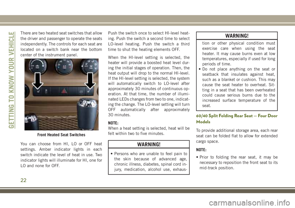
There are two heated seat switches that allow
the driver and passenger to operate the seats
independently. The controls for each seat are
located on a switch bank near the bottom
center of the instrument panel.
You can choose from HI, LO or OFF heat
settings. Amber indicator lights in each
switch indicate the level of heat in use. Two
indicator lights will illuminate for HI, one for
LO and none for OFF.Push the switch once to select HI-level heat-
ing. Push the switch a second time to select
LO-level heating. Push the switch a third
time to shut the heating elements OFF.
When the HI-level setting is selected, the
heater will provide a boosted heat level dur-
ing the initial stages of operation. Then, the
heat output will drop to the normal HI-level.
If the HI-level setting is selected, the system
will automatically switch to LO-level after
approximately 30 minutes of continuous op-
eration. At that time, the number of illumi-
nated LEDs changes from two to one, indicat-
ing the change. The LO-level setting will turn
OFF automatically after approximately
30 minutes.
NOTE:
When a heat setting is selected, heat will be
felt within two to five minutes.
WARNING!
• Persons who are unable to feel pain to
the skin because of advanced age,
chronic illness, diabetes, spinal cord in-
jury, medication, alcohol use, exhaus-
WARNING!
tion or other physical condition must
exercise care when using the seat
heater. It may cause burns even at low
temperatures, especially if used for long
periods of time.
• Do not place anything on the seat or
seatback that insulates against heat,
such as a blanket or cushion. This may
cause the seat heater to overheat. Sit-
ting in a seat that has been overheated
could cause serious burns due to the
increased surface temperature of the
seat.
60/40 Split Folding Rear Seat — Four Door
Models
To provide additional storage area, each rear
seat can be folded flat to allow for extended
cargo space.
NOTE:
• Prior to folding the rear seat, it may be
necessary to reposition the front seat to its
mid-track position.Front Heated Seat Switches
GETTING TO KNOW YOUR VEHICLE
22
Page 32 of 276
NOTE:
• If either light remains on and does not
flash, or there is a very fast flash rate, check
for a defective outside light bulb. If an
indicator fails to light when the lever is
moved, it would suggest that the indicator
bulb is defective.
• A tone will chime if the turn signals are left
on for more than 1 mile (2 km).
Lane Change Assist — If Equipped
Tap the lever up or down once, without mov-
ing beyond the detent, and the turn signal
(right or left) will flash three times then
automatically turn off.
Lights-On Reminder
If the headlights, parking lights, or cargo
lights are left on after the ignition is turned
OFF, a chime will sound when the driver’s
door is opened.
Headlight Leveling System — If Equipped
Your vehicle may be equipped with a head-
light leveling system. This system allows the
driver to maintain proper headlight beam
position with the road surface regardless of
vehicle load.
The control switch is located in the switch
bank below the climate controls.
To operate, push the control switch until the
indicator next to the appropriate number,
which corresponds to the load listed on the
chart below, illuminates on the switch.
0/1Driver only, or driver
and front passenger.
2All seating positions
occupied, plus an
evenly distributed
load in the luggage
compartment. The
total weight of pas-
sengers and load
does not exceed the
maximum load ca-
pacity of the vehicle.
3Driver, plus an evenly
distributed load in
the luggage compart-
ment. The total
weight of the driver
and load does not
exceed the maximum
load capacity of the
vehicle.
WINDSHIELD WIPERS AND
WASHERS
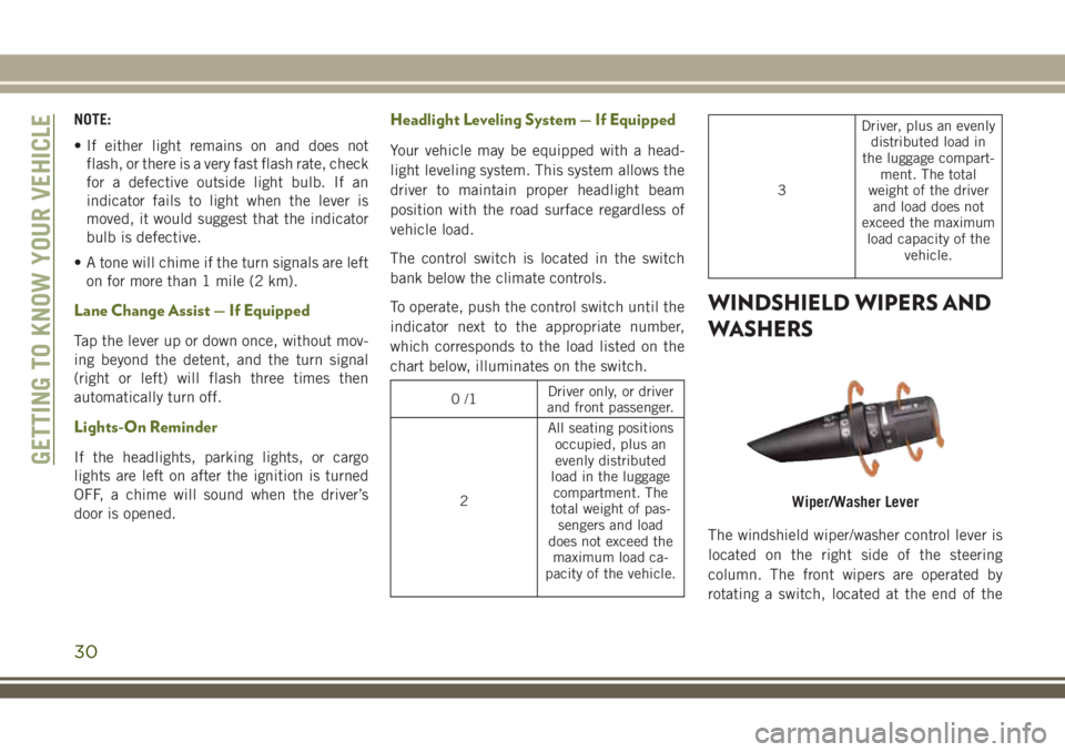
The windshield wiper/washer control lever is
located on the right side of the steering
column. The front wipers are operated by
rotating a switch, located at the end of the
Wiper/Washer Lever
GETTING TO KNOW YOUR VEHICLE
30
Page 64 of 276
and automatic transmission control systems.
The light will illuminate when the ignition is
in the ON/RUN position before engine start.
If the bulb does not come on when turning
the ignition switch from OFF to ON/RUN,
have the condition checked promptly.
Certain conditions, such as a loose or missing
gas cap, poor quality fuel, etc., may illumi-
nate the light after engine start. The vehicle
should be serviced if the light stays on
through several typical driving styles. In most
situations, the vehicle will drive normally and
will not require towing.
When the engine is running, the MIL may
flash to alert serious conditions that could
lead to immediate loss of power or severe
catalytic converter damage. The vehicle
should be serviced as soon as possible if this
occurs.
WARNING!
A malfunctioning catalytic converter, as
referenced above, can reach higher tem-
peratures than in normal operating condi-
tions. This can cause a fire if you drive
WARNING!
slowly or park over flammable substances
such as dry plants, wood, cardboard, etc.
This could result in death or serious injury
to the driver, occupants or others.
CAUTION!
Prolonged driving with the Malfunction
Indicator Light (MIL) on could cause dam-
age to the vehicle control system. It also
could affect fuel economy and driveability.
If the MIL is flashing, severe catalytic
converter damage and power loss will soon
occur. Immediate service is required.
— Tire Pressure Monitoring System
(TPMS) Warning Light
The warning light switches on and a message
is displayed to indicate that the tire pressure
is lower than the recommended value and/or
that slow pressure loss is occurring. In these
cases, optimal tire duration and fuel con-
sumption may not be guaranteed.Should one or more tires be in the condition
mentioned above, the display will show the
indications corresponding to each tire in
sequence.
CAUTION!
Do not continue driving with one or more
flat tires as handling may be compro-
mised. Stop the vehicle, avoiding sharp
braking and steering. If a tire puncture
occurs, repair immediately using the dedi-
cated tire repair kit and contact your au-
thorized dealer as soon as possible.
Each tire, including the spare (if provided),
should be checked monthly when cold and
inflated to the inflation pressure recom-
mended by the vehicle manufacturer on the
vehicle placard or tire inflation pressure la-
bel. (If your vehicle has tires of a different
size than the size indicated on the vehicle
placard or tire inflation pressure label, you
should determine the proper tire inflation
pressure for those tires.)
GETTING TO KNOW YOUR INSTRUMENT PANEL
62
Page 65 of 276
As an added safety feature, your vehicle has
been equipped with a tire pressure monitor-
ing system (TPMS) that illuminates a low tire
pressure telltale when one or more of your
tires is significantly under-inflated. Accord-
ingly, when the low tire pressure telltale illu-
minates, you should stop and check your tires
as soon as possible, and inflate them to the
proper pressure. Driving on a significantly
under-inflated tire causes the tire to overheat
and can lead to tire failure. Under-inflation
also reduces fuel efficiency and tire tread
life, and may affect the vehicle’s handling
and stopping ability.
Please note that the TPMS is not a substitute
for proper tire maintenance, and it is the
driver’s responsibility to maintain correct tire
pressure, even if under-inflation has not
reached the level to trigger illumination of the
TPMS low tire pressure telltale.
Your vehicle has also been equipped with a
TPMS malfunction indicator to indicate when
the system is not operating properly. The
TPMS malfunction indicator is combined
with the low tire pressure telltale. When the
system detects a malfunction, the telltale willflash for approximately one minute and then
remain continuously illuminated. This se-
quence will continue upon subsequent ve-
hicle start-ups as long as the malfunction
exists. When the malfunction indicator is
illuminated, the system may not be able to
detect or signal low tire pressure as intended.
TPMS malfunctions may occur for a variety of
reasons, including the installation of replace-
ment or alternate tires or wheels on the ve-
hicle that prevent the TPMS from functioning
properly. Always check the TPMS malfunc-
tion telltale after replacing one or more tires
or wheels on your vehicle to ensure that the
replacement or alternate tires and wheels
allow the TPMS to continue to function
properly.
CAUTION!
The TPMS has been optimized for the
original equipment tires and wheels.
TPMS pressures and warning have been
established for the tire size equipped on
your vehicle. Undesirable system opera-
tion or sensor damage may result when
using replacement equipment that is not
CAUTION!
of the same size, type, and/or style. After-
market wheels can cause sensor damage.
Using aftermarket tire sealants may cause
the Tire Pressure Monitoring System
(TPMS) sensor to become inoperable. Af-
ter using an aftermarket tire sealant it is
recommended that you take your vehicle to
your authorized dealer to have your sensor
function checked.
Yellow Indicator Lights
— Front Axle Lock Indicator Light — If
Equipped
Indicates when the front axle lock has been
activated.
— Rear Axle Lock Indicator Light — If
Equipped
This light indicates when the rear axle lock
has been activated.
63
Page 66 of 276
— 4WD Indicator Light — If Equipped
This light alerts the driver that the vehicle is
in the four-wheel drive mode, and the front
and rear driveshafts are mechanically locked
together forcing the front and rear wheels to
rotate at the same speed.
— Sway Bar Indicator Light — If
Equipped
This indicator will illuminate when the front
sway bar is disconnected.
Green Indicator Lights
— Front Fog Indicator Light — If
Equipped
This indicator will illuminate when the front
fog lights are on.
— Turn Signal Indicator Lights
When the left or right turn signal is activated,
the turn signal indicator will flash indepen-
dently and the corresponding exterior turn
signal lamps will flash. Turn signals can be
activated when the multifunction lever is
moved down (left) or up (right).NOTE:
• A continuous chime will sound if the ve-
hicle is driven more than 1 mile (1.6 km)
with either turn signal on.
• Check for an inoperative outside light bulb
if either indicator flashes at a rapid rate.
White Indicator Lights
CRUISE— Cruise Indicator
This indicator shows that the Speed Control
System is ON.
— Hill Descent Control (HDC) Indicator
Light — If Equipped
This indicator shows when the Hill Descent
Control (HDC) feature is turned on. The lamp
will be on solid when HDC is armed. HDC can
only be armed when the transfer case is in the
“4WD LOW” position and the vehicle speed
is less then 30 mph (48 km/h). If these
conditions are not met while attempting to
use the HDC feature, the HDC indicator light
will flash on/off.
Blue Indicator Lights
— High Beam Indicator Light
This indicator shows that the high beam
headlights are on. With the low beams acti-
vated, push the multifunction lever forward
(toward the front of the vehicle) to turn on the
high beams. Pull the multifunction lever rear-
ward (toward the rear of the vehicle) to turn
off the high beams. If the high beams are off,
pull the lever toward you for a temporary high
beam on, "flash to pass" scenario.
ONBOARD DIAGNOSTIC
SYSTEM — OBD II
Your vehicle is equipped with a sophisticated
Onboard Diagnostic system called OBD II.
This system monitors the performance of the
emissions, engine, and automatic transmis-
sion control systems. When these systems are
operating properly, your vehicle will provide
excellent performance and fuel economy, as
well as engine emissions well within current
government regulations.
GETTING TO KNOW YOUR INSTRUMENT PANEL
64
Page 72 of 276
WARNING!
speed in turns, driving on very slippery
surfaces, or hydroplaning. The capabilities
of a BAS-equipped vehicle must never be
exploited in a reckless or dangerous man-
ner, which could jeopardize the user's
safety or the safety of others.
Hill Start Assist (HSA)
The HSA system is designed to mitigate roll
back from a complete stop while on an in-
cline. If the driver releases the brake while
stopped on an incline, HSA will continue to
hold the brake pressure for a short period. If
the driver does not apply the throttle before
this time expires, the system will release
brake pressure and the vehicle will roll down
the hill as normal.
The following conditions must be met in
order for HSA to activate:
• The feature must be enabled.
• The vehicle must be stopped.
• Park brake must be off.• Driver door must be closed.
• The vehicle must be on a sufficient grade.
• The gear selection must match vehicle up-
hill direction (i.e., vehicle facing uphill is in
forward gear; vehicle backing uphill is in
REVERSE gear).
• HSA will work in REVERSE gear and all
forward gears. The system will not activate
if the transmission is in PARK or NEU-
TRAL. For vehicles equipped with a manual
transmission, if the clutch is pressed, HSA
will remain active.
WARNING!
There may be situations where the Hill
Start Assist (HSA) will not activate and
slight rolling may occur, such as on minor
hills or with a loaded vehicle, or while
pulling a trailer. HSA is not a substitute for
active driving involvement. It is always the
driver’s responsibility to be attentive to
distance to other vehicles, people, and
objects, and most importantly brake op-
eration to ensure safe operation of the
vehicle under all road conditions. Your
WARNING!
complete attention is always required
while driving to maintain safe control of
your vehicle. Failure to follow these warn-
ings can result in a collision or serious
personal injury.
Disabling And Enabling HSA
This feature can be turned on or turned off.
To change the current setting using your
instrument cluster display, refer to “Instru-
ment Cluster Display” in “Getting To Know
Your Instrument Panel” for further informa-
tion.
For vehicles not equipped with an instrument
cluster display, perform the following steps:
1. Center the steering wheel (front wheels
pointing straight forward).
2. Shift the transmission into PARK.
3. Apply the parking brake.
4. Start the engine.
5. Rotate the steering wheel slightly more
than one-half turn to the left.
SAFETY
70
Page 78 of 276
WARNING!
Many factors, such as vehicle loading,
road conditions and driving conditions,
influence the chance that wheel lift or
rollover may occur. ERM cannot prevent
all wheel lift or roll overs, especially those
that involve leaving the roadway or striking
objects or other vehicles. The capabilities
of an ERM-equipped vehicle must never
be exploited in a reckless or dangerous
manner which could jeopardize the user's
safety or the safety of others.
Trailer Sway Control (TSC)
TSC uses sensors in the vehicle to recognize
an excessively swaying trailer and will take
the appropriate actions to attempt to stop the
sway. TSC will become active automatically
once an excessively swaying trailer is recog-
nized.NOTE:
TSC cannot stop all trailers from swaying.
Always use caution when towing a trailer and
follow the trailer tongue weight recommenda-
tions. Refer to “Trailer Towing” in “Starting
And Operating” for further information.
When TSC is functioning, the “ESC
Activation/Malfunction Indicator Light” will
flash, the engine power may be reduced and
you may feel the brakes being applied to
individual wheels to attempt to stop the
trailer from swaying. TSC is disabled when
the ESC system is in the “Partial Off” or “Full
Off” modes.WARNING!
If TSC activates while driving, slow the
vehicle down, stop at the nearest safe
location, and adjust the trailer load to
eliminate trailer sway.
Hill Descent Control (HDC) — If Equipped
HDC is only intended for low speed off-road
driving. HDC maintains vehicle speed while
descending hills in off-road driving condi-
tions by applying the brakes when necessary.
The symbol indicates the status
of the Hill Descent Control
(HDC) feature. The lamp will be
on solid when HDC is armed.
HDC can only be armed when the
transfer case is in the “4WD LOW” position
and the vehicle speed is less then 30 mph
(48 km/h). If these conditions are not met
while attempting to use the HDC feature, the
HDC indicator light will flash on/off.
When enabled, HDC senses the terrain and acti-
vates when the vehicle is descending a hill. HDC
speed may be adjusted by the driver to suit the
driving conditions. The speed corresponds to the
transmission gear selected.
Gear Approximate HDC Set
Speed
1st 1 mph (1.5 km/h)
2nd 2.5 mph (4 km/h)
SAFETY
76
Page 81 of 276
• Driving on a significantly under-inflated tire
causes the tire to overheat and can lead to
tire failure. Under-inflation also reduces
fuel efficiency and tire tread life, and may
affect the vehicle’s handling and stopping
ability.
• The TPMS is not a substitute for proper tire
maintenance, and it is the driver’s respon-
sibility to maintain correct tire pressure,
even if under-inflation has not reached the
level to trigger illumination of the “Tire
Pressure Monitoring Telltale Light.”
• Seasonal temperature changes will affect
tire pressure, and the TPMS will monitor
the actual tire pressure in the tire.
Base System
The Tire Pressure Monitor System (TPMS)
uses wireless technology with wheel rim-
mounted electronic sensors to monitor tire
pressure levels. Sensors, mounted to each
wheel as part of the valve stem, transmit tire
pressure readings to the Receiver Module.NOTE:
It is particularly important for you to check
the tire pressure in all of your tires regularly
and to maintain the proper pressure.
The Tire Pressure Monitor System (TPMS)
consists of the following components:
• Receiver Module
• Four Tire Pressure Monitoring Sensors
• Tire Pressure Monitoring Telltale Light
A tire pressure monitoring sensor is located in
the spare wheel if the vehicle is equipped
with a matching full size spare wheel and tire
assembly. The matching full size spare tire
can be used in place of any of the four road
tires. A low spare tire will not cause the “Tire
Pressure Monitoring Telltale Light” to illumi-
nate or the chime to sound while stowed in
the spare location.
The “Tire Pressure Monitoring Tell-
tale Light” will illuminate in the in-
strument cluster, a “LOW TIRE
PRESSURE” message will display in the in-
strument cluster, and an audible chime will
be activated when one or more of the four
active road tire pressures are low. Should thisoccur, you should stop as soon as possible,
check the inflation pressure of each tire on
your vehicle, and inflate each tire to the
vehicle's recommended cold placard pres-
sure value. The system will automatically
update and the “Tire Pressure Monitoring
Telltale Light” will extinguish once the up-
dated tire pressures have been received. The
vehicle may need to be driven for up to
10 minutes above 15 mph (24 km/h) to
receive this information
The “Tire Pressure Monitoring Telltale Light”
will flash on and off for 75 seconds, and will
remain on solid when a system fault is de-
tected. The system fault will also sound a
chime. If the ignition key is cycled, this
sequence will repeat, providing the system
fault still exists. The “Tire Pressure Monitor-
ing Telltale Light” will turn off when the fault
condition no longer exists. A system fault can
occur by any of the following scenarios:
1. Jamming due to electronic devices or driv-
ing next to facilities emitting the same
Radio Frequencies as the TPM sensors.
79
Page 98 of 276
properly, or if items are positioned in the area
where the SAB inflates. Children are at an
even greater risk of injury from a deploying air
bag.
WARNING!
Do not use accessory seat covers or place
objects between you and the Side Air
Bags; the performance could be adversely
affected and/or objects could be pushed
into you, causing serious injury.
Side Impacts
The Side Air Bags are designed to activate in
certain side impacts. The Occupant Restraint
Controller (ORC) determines whether the de-
ployment of the Side Air Bags in a particular
impact event is appropriate, based on the
severity and type of collision. The side impact
sensors aid the ORC in determining the ap-
propriate response to impact events. The
system is calibrated to deploy the Side Air
Bags on the impact side of the vehicle during
impacts that require Side Air Bag occupant
protection. In side impacts, the Side Air Bags
deploy independently; a left side impact de-ploys the left Side Air Bags only and a right-
side impact deploys the right Side Air Bags
only. Vehicle damage by itself is not a good
indicator of whether or not Side Air Bags
should have deployed.
The Side Air Bags will not deploy in all side
collisions, including some collisions at cer-
tain angles, or some side collisions that do
not impact the area of the passenger com-
partment. The Side Air Bags may deploy
during angled or offset frontal collisions
where the front air bags deploy.
Side Air Bags are a supplement to the seat
belt restraint system. Side Air Bags deploy in
less time than it takes to blink your eyes.
WARNING!
• Occupants, including children, who are
up against or very close to Side Air Bags
can be seriously injured or killed. Occu-
pants, including children, should never
lean on or sleep against the door, side
windows, or area where the side air bags
inflate, even if they are in an infant or
child restraint.
WARNING!
• Seat belts (and child restraints where
appropriate) are necessary for your pro-
tection in all collisions. They also help
keep you in position, away from an in-
flating Side Air Bag. To get the best
protection from the Side Air Bags, occu-
pants must wear their seat belts properly
and sit upright with their backs against
the seats. Children must be properly
restrained in a child restraint or booster
seat that is appropriate for the size of the
child.
WARNING!
• Side Air Bags need room to inflate. Do
not lean against the door or window. Sit
upright in the center of the seat.
• Being too close to the Side Air Bags
during deployment could cause you to
be severely injured or killed.
• Relying on the Side Air Bags alone could
lead to more severe injuries in a colli-
sion. The Side Air Bags work with your
seat belt to restrain you properly. In
SAFETY
96