torque JEEP WRANGLER 2021 Owner handbook (in English)
[x] Cancel search | Manufacturer: JEEP, Model Year: 2021, Model line: WRANGLER, Model: JEEP WRANGLER 2021Pages: 276, PDF Size: 4.47 MB
Page 21 of 276
DOORS
CAUTION!
Careless handling and storage of the re-
movable door panels may damage the
seals, causing water to leak into the vehi-
cle’s interior.
Upper Half Door Window Removal — If
Equipped
Grasp the half door window and pull upward.
Upper Half Door Window Installation — If
Equipped
1.Grasp the half door window and line up the
pins with the pockets in the lower door.
2. Push down to ensure the half door window
is fully seated.
Front Door Removal
WARNING!
Do not drive your vehicle on public roads
with the doors removed as you will lose the
WARNING!
protection they can provide. This proce-
dure is furnished for use during off-road
operation only.
NOTE:
Hinge pin can break if overtightened during
door reinstall (Max Torque: 10 N·m / 7.5 ft· lb).
1. Roll down the glass window to prevent any
damage.
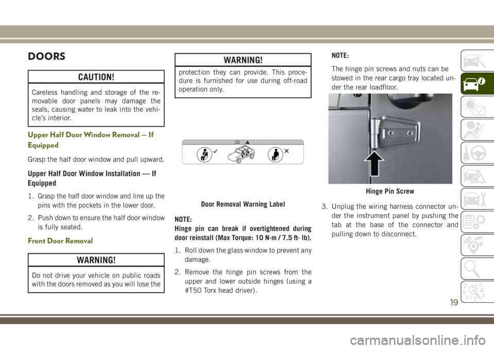
2. Remove the hinge pin screws from the
upper and lower outside hinges (using a
#T50 Torx head driver).NOTE:
The hinge pin screws and nuts can be
stowed in the rear cargo tray located un-
der the rear loadfloor.
3. Unplug the wiring harness connector un-
der the instrument panel by pushing the
tab at the base of the connector and
pulling down to disconnect.
Door Removal Warning Label
Hinge Pin Screw
19
Page 22 of 276
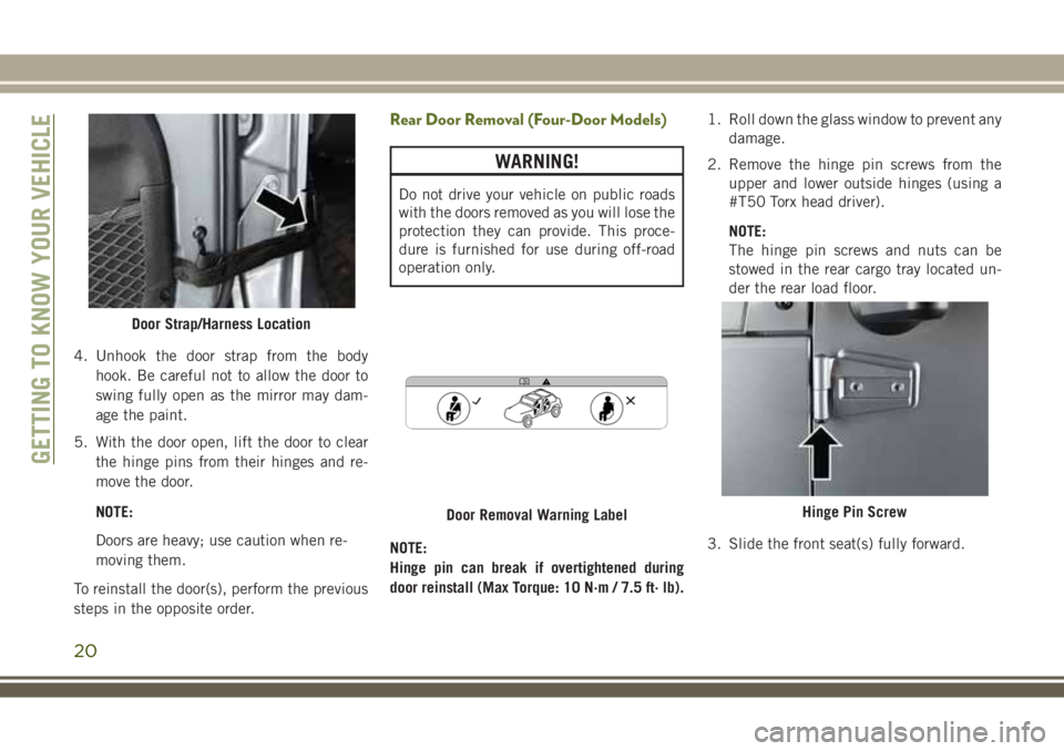
4. Unhook the door strap from the body
hook. Be careful not to allow the door to
swing fully open as the mirror may dam-
age the paint.
5. With the door open, lift the door to clear
the hinge pins from their hinges and re-
move the door.
NOTE:
Doors are heavy; use caution when re-
moving them.
To reinstall the door(s), perform the previous
steps in the opposite order.
Rear Door Removal (Four-Door Models)
WARNING!
Do not drive your vehicle on public roads
with the doors removed as you will lose the
protection they can provide. This proce-
dure is furnished for use during off-road
operation only.
NOTE:
Hinge pin can break if overtightened during
door reinstall (Max Torque: 10 N·m / 7.5 ft· lb).1. Roll down the glass window to prevent any
damage.
2. Remove the hinge pin screws from the
upper and lower outside hinges (using a
#T50 Torx head driver).
NOTE:
The hinge pin screws and nuts can be
stowed in the rear cargo tray located un-
der the rear load floor.
3. Slide the front seat(s) fully forward.
Door Strap/Harness Location
Door Removal Warning LabelHinge Pin Screw
GETTING TO KNOW YOUR VEHICLE
20
Page 71 of 276
required. However, the conventional brake
system will continue to operate normally if
the “Brake System Warning Light” is not on.
If the “Anti-Lock Brake Warning Light” is on,
the brake system should be serviced as soon
as possible to restore the benefits of anti-lock
brakes. If the “Anti-Lock Brake Warning
Light” does not come on when the ignition is
turned to the ON/RUN mode, have the light
repaired as soon as possible.
Electronic Brake Control System
Your vehicle is equipped with an advanced
Electronic Brake Control system (EBC). This
system includes Electronic Brake Force Dis-
tribution (EBD), Brake Assist System (BAS),
Hill Start Assist (HSA), Traction Control Sys-
tem (TCS), Electronic Stability Control
(ESC), and Electronic Roll Mitigation (ERM).
These systems work together to enhance both
vehicle stability and control in various driving
conditions.
Your vehicle may also be equipped with
Trailer Sway Control (TSC) and Hill Descent
Control (HDC).
Electronic Brake Force Distribution (EBD)
This function manages the distribution of the
braking torque between the front and rear
axles by limiting braking pressure to the rear
axle. This is done to prevent overslip of the
rear wheels to avoid vehicle instability, and to
prevent the rear axle from entering ABS be-
fore the front axle.
Brake System Warning Light
The red “Brake System Warning Light” will
turn on when the ignition is turned to the
ON/RUN mode and may stay on for as long as
four seconds.
If the “Brake System Warning Light” remains
on or comes on while driving, it indicates that
the brake system is not functioning properly
and that immediate service is required. If the
“Brake System Warning Light” does not
come on when the ignition is turned to the
ON/RUN mode, have the light repaired as
soon as possible.
Brake Assist System (BAS)
The BAS is designed to optimize the vehicle’s
braking capability during emergency braking
maneuvers. The system detects an emer-
gency braking situation by sensing the rate
and amount of brake application and then
applies optimum pressure to the brakes. This
can help reduce braking distances. The BAS
complements the anti-lock brake system
(ABS). Applying the brakes very quickly re-
sults in the best BAS assistance. To receive
the benefit of the system, you must apply
continuous braking pressure during the stop-
ping sequence, (do not “pump” the brakes).
Do not reduce brake pedal pressure unless
braking is no longer desired. Once the brake
pedal is released, the BAS is deactivated.
WARNING!
The Brake Assist System (BAS) cannot
prevent the natural laws of physics from
acting on the vehicle, nor can it increase
the traction afforded by prevailing road
conditions. BAS cannot prevent collisions,
including those resulting from excessive
69
Page 73 of 276
6. Push the “ESC Off” button located in the
lower switch bank below the climate con-
trol four times within 20 seconds. The
“ESC Off Indicator Light” should turn on
and turn off two times.
7. Rotate the steering wheel back to center
and then an additional slightly more than
one-half turn to the right.
8. Turn the ignition to the OFF mode and
then back to ON. If the sequence was
completed properly, the “ESC Off Indica-
tor Light” will blink several times to con-
firm HSA is disabled.
9. Repeat these steps if you want to return
this feature to its previous setting.
Traction Control System (TCS)
This system monitors the amount of wheel
spin of each of the driven wheels. If wheel
spin is detected, the TCS may apply brake
pressure to the spinning wheel(s) and/or re-
duce engine power to provide enhanced ac-
celeration and stability. A feature of the TCS,
Brake Limited Differential (BLD), functions
similar to a limited slip differential and con-
trols the wheel spin across a driven axle. Ifone wheel on a driven axle is spinning faster
than the other, the system will apply the
brake of the spinning wheel. This will allow
more engine torque to be applied to the wheel
that is not spinning. BLD may remain en-
abled even if TCS and ESC are in a reduced
mode.
Electronic Stability Control (ESC)
This system enhances directional control and
stability of the vehicle under various driving
conditions. The ESC corrects for over/under
steering of the vehicle by applying the brake
of the appropriate wheel to assist in counter-
acting the over/under steer condition. Engine
power may also be reduced to help the ve-
hicle maintain the desired path.
ESC uses sensors in the vehicle to determine
the vehicle path intended by the driver and
compares it to the actual path of the vehicle.
When the actual path does not match the
intended path, ESC applies the brake of the
appropriate wheel to assist in counteracting
the oversteer or understeer condition.
• Oversteer - when the vehicle is turning more
than appropriate for the steering wheel po-
sition.• Understeer - when the vehicle is turning
less than appropriate for the steering wheel
position.
The “ESC Activation/Malfunction Indicator
Light” (located in the instrument cluster),
starts to flash as soon as the tires lose trac-
tion and the ESC system becomes active. The
“ESC Activation/Malfunction Indicator
Light” also flashes when TCS is active. If the
“ESC Activation/Malfunction Indicator
Light” begins to flash during acceleration,
ease up on the accelerator and apply as little
throttle as possible. Be sure to adapt your
speed and driving to the prevailing road
conditions.
WARNING!
• Electronic Stability Control (ESC) can-
not prevent the natural laws of physics
from acting on the vehicle, nor can it
increase the traction afforded by prevail-
ing road conditions. ESC cannot prevent
accidents, including those resulting
from excessive speed in turns, driving on
very slippery surfaces, or hydroplaning.
71
Page 75 of 276
WARNING!
hicle stability offered by the ESC system
is reduced.
• Trailer Sway control (TSC) is disabled
when the ESC system is in the "ESC
Partial Off" mode.
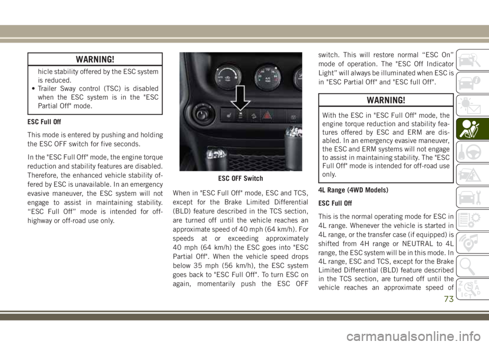
ESC Full Off
This mode is entered by pushing and holding
the ESC OFF switch for five seconds.
In the "ESC Full Off" mode, the engine torque
reduction and stability features are disabled.
Therefore, the enhanced vehicle stability of-
fered by ESC is unavailable. In an emergency
evasive maneuver, the ESC system will not
engage to assist in maintaining stability.
“ESC Full Off” mode is intended for off-
highway or off-road use only.When in "ESC Full Off" mode, ESC and TCS,
except for the Brake Limited Differential
(BLD) feature described in the TCS section,
are turned off until the vehicle reaches an
approximate speed of 40 mph (64 km/h). For
speeds at or exceeding approximately
40 mph (64 km/h) the ESC goes into "ESC
Partial Off". When the vehicle speed drops
below 35 mph (56 km/h), the ESC system
goes back to "ESC Full Off". To turn ESC on
again, momentarily push the ESC OFFswitch. This will restore normal “ESC On”
mode of operation. The "ESC Off Indicator
Light” will always be illuminated when ESC is
in "ESC Partial Off" and "ESC full Off".
WARNING!
With the ESC in "ESC Full Off" mode, the
engine torque reduction and stability fea-
tures offered by ESC and ERM are dis-
abled. In an emergency evasive maneuver,
the ESC and ERM systems will not engage
to assist in maintaining stability. The "ESC
Full Off" mode is intended for off-road use
only.
4L Range (4WD Models)
ESC Full Off
This is the normal operating mode for ESC in
4L range. Whenever the vehicle is started in
4L range, or the transfer case (if equipped) is
shifted from 4H range or NEUTRAL to 4L
range, the ESC system will be in this mode. In
4L range, ESC and TCS, except for the Brake
Limited Differential (BLD) feature described
in the TCS section, are turned off until the
vehicle reaches an approximate speed of
ESC OFF Switch
73
Page 76 of 276
40 mph (64 km/h). For speeds at or exceed-
ing approximately 40 mph (64 km/h) the ESC
goes into "ESC Partial Off" When the vehicle
speed drops below 35 mph (56 km/h), the
ESC system goes back to "ESC Full Off". The
ESC is in "ESC Full Off" at low vehicle speeds
in 4L range so that it will not interfere with
off-road driving, but the ESC function returns
to provide the stability feature at speeds
above 40 mph (64 km/h). The “ESC OFF
Indicator Light” will always be illuminated in
4L range when ESC is in "ESC Full Off" or
"ESC Partial Off".
NOTE:
The “ESC OFF” message will display and an
audible chime will sound when the gear se-
lector is placed in the PARK position from
any other position, and then moved out of the
PARK position. This will occur even if the
message was previously cleared.
WARNING!
With the ESC in "ESC Full Off" mode, the
engine torque reduction and stability fea-
tures offered by ESC and ERM are dis-
WARNING!
abled. In an emergency evasive maneuver,
the ESC and ERM systems will not engage
to assist in maintaining stability. The "ESC
Full Off" mode is intended for off-road use
only.
2H Range (4WD Models) Or 2WD Models
ESC On
This is the normal operating mode for ESC in
2H range and on 2WD vehicles.
ESC Partial Off
When in "ESC Partial Off" mode, the TCS
portion of ESC (except for the limited slip
feature described in the TCS section), has
been disabled and the "ESC Off Indicator
Light" will be illuminated.
This mode is intended to be used if the
vehicle is in deep snow, sand, or gravel con-
ditions and more wheel spin than ESC would
normally allow is required to gain traction. To
turn ESC on again, momentarily push the
ESC OFF switch. This will restore the normal
"ESC On" mode of operation.NOTE:
To improve the vehicle’s traction when driving
with snow chains, or starting off in deep
snow, sand, or gravel, it may be desirable to
switch to the "ESC Partial Off" mode by
pushing the "ESC Full Off" switch. Once the
situation requiring ESC to be switched to the
"ESC Partial Off" mode is overcome, turn ESC
back on by momentarily pushing the "ESC
Full Off" switch. This may be done while the
vehicle is in motion.
The ESC will restore to normal ESC On mode
after each key on.
WARNING!
• When in “Partial Off” mode, the TCS
functionality of ESC, (except for the lim-
ited slip feature described in the TCS
section), has been disabled and the
“ESC Off Indicator Light” will be illumi-
nated. When in “Partial Off” mode, the
engine power reduction feature of TCS is
disabled, and the enhanced vehicle sta-
bility offered by the ESC system is re-
duced.
SAFETY
74
Page 134 of 276
NOTE:
Shifting into or out of 4L is possible with the
vehicle completely stopped; however, diffi-
culty may occur due to the mating teeth not
being properly aligned. Several attempts may
be required for clutch teeth alignment and
shift completion to occur. The preferred
method is with the vehicle rolling at 2 to
3 mph (3 to 5 km/h). Avoid attempting to
engage or disengage 4L with the vehicle
moving faster than 2 to 3 mph (3 to 5 km/h).
WARNING!
Failure to engage a transfer case position
completely can cause transfer case dam-
age or loss of power and vehicle control.
You could have a collision. Do not drive the
vehicle unless the transfer case is fully
engaged.
Trac-Lok Rear Axle — If Equipped
The Trac-Lok rear axle provides a constant
driving force to both rear wheels and reduces
wheel spin caused by the loss of traction at
one driving wheel. If traction differs between
the two rear wheels, the differential auto-
matically proportions the usable torque by
providing more torque to the wheel that has
traction.
Trac-Lok is especially helpful during slippery
driving conditions. With both rear wheels on a
slippery surface, a slight application of the
accelerator will supply maximum traction.
WARNING!
On vehicles equipped with a limited-slip
differential, never run the engine with one
rear wheel off the ground. The vehicle may
drive through the rear wheel remaining on
the ground and cause you to lose control of
your vehicle.
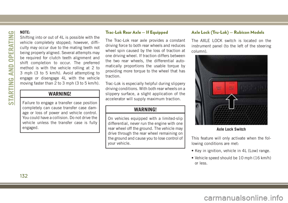
Axle Lock (Tru-Lok) — Rubicon Models
The AXLE LOCK switch is located on the
instrument panel (to the left of the steering
column).
This feature will only activate when the fol-
lowing conditions are met:
• Key in ignition, vehicle in 4L (Low) range.
• Vehicle speed should be 10 mph (16 km/h)
or less.
Axle Lock Switch
STARTING AND OPERATING
132
Page 136 of 276
tion for further information. The “Sway Bar
Indicator Light” will flash until the stabilizer/
sway bar has been fully disconnected.
NOTE:
The stabilizer/sway bar may be torque locked
due to left and right suspension height differ-
ences. This condition is due to driving sur-
face differences or vehicle loading. In order
for the stabilizer/sway bar to disconnect/
reconnect, the right and left halves of the bar
must be aligned. This alignment may require
that the vehicle be driven onto level ground or
rocked from side to side.
To return to on-road mode, push the SWAY
BAR switch again.
WARNING!
If the stabilizer/sway bar will not return to
on-road mode, the “Sway Bar Indicator
Light” will flash in the instrument cluster
and vehicle stability is greatly reduced. Do
not attempt to drive the vehicle over
18 mph (29 km/h). Driving faster than
18 mph (29 km/ h) may cause loss of
control of the vehicle, which could result
WARNING!
in serious injury. Contact your local autho-
rized dealer for assistance.
STOP/START SYSTEM —
DIESEL MODELS WITH
MANUAL TRANSMISSION
ONLY
The Stop/Start function is developed to save
fuel and reduce emissions. The system will
stop the engine automatically during a ve-
hicle stop if the required conditions are met.
Pressing the clutch pedal will automatically
restart the vehicle.
Automatic Mode
The Stop/Start feature is en-
abled after every normal cus-
tomer engine start. It will remain
in STOP/START NOT READY un-
til you drive forward with a ve-
hicle speed greater than 3 mph (5 km/h). Atthat time, the system will go into STOP/
START READY and if all other conditions are
met, can go into an STOP/START AUTO STOP
ACTIVE mode.
To Activate The STOP/START AUTO STOP ACTIVE
Mode, The Following Must Occur:
• The system must be in STOP/START
READY state. A STOP/START READY mes-
sage will be displayed in the instrument
cluster. Refer to “Instrument Cluster Dis-
play” in “Getting To Know Your Instrument
Panel” for further information.
• Vehicle speed must be less 3 mph (5 km/h).
• The gear selector must be in the NEUTRAL
position and the clutch pedal must be fully
released
The engine will shut down,the tachometer will
fall to the Stop/Start position,the STOP/START
AUTO STOP ACTIVE message will appear,
and the heater/air conditioning (HVAC) air
flow will be reduced.
STARTING AND OPERATING
134
Page 159 of 276
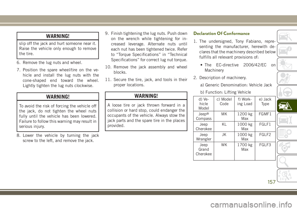
WARNING!
slip off the jack and hurt someone near it.
Raise the vehicle only enough to remove
the tire.
6. Remove the lug nuts and wheel.
7. Position the spare wheel/tire on the ve-
hicle and install the lug nuts with the
cone-shaped end toward the wheel.
Lightly tighten the lug nuts clockwise.
WARNING!
To avoid the risk of forcing the vehicle off
the jack, do not tighten the wheel nuts
fully until the vehicle has been lowered.
Failure to follow this warning may result in
serious injury.
8. Lower the vehicle by turning the jack
screw to the left, and remove the jack.9. Finish tightening the lug nuts. Push down
on the wrench while tightening for in-
creased leverage. Alternate nuts until
each nut has been tightened twice. Refer
to “Torque Specifications” in “Technical
Specifications” for correct lug nut torque.
10. Remove the jack assembly and wheel
blocks.
11. Secure the tire, jack, and tools in their
proper locations.
WARNING!
A loose tire or jack thrown forward in a
collision or hard stop, could endanger the
occupants of the vehicle. Always stow the
jack parts and the spare tire in the places
provided.
Declaration Of Conformance
1. The undersigned, Tony Fabiano, repre-
senting the manufacturer, herewith de-
clares that the machinery described below
fulfills all relevant provisions of:
• The EC-directive 2006/42/EC on
Machinery
2. Description of machinery.
a) Generic Denomination: Vehicle Jack
b) Function: Lifting Vehicle
d) Ve-
hicle
Modelc) Model
Codef) Work-
ing Loade) Jack
Type
Jeep
®
CompassMK 1200 kg
MaxFGMF1
Jeep
CherokeeKL 1000 kg
MaxFGLF1
Jeep
WranglerJK 1000 kg
MaxFGLF2
Jeep
Grand
CherokeeWK 1700 kg
MaxFGLF3
157
Page 209 of 276
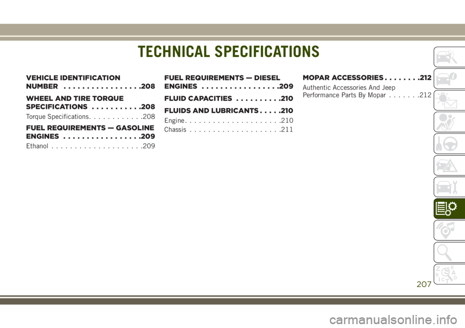
TECHNICAL SPECIFICATIONS
VEHICLE IDENTIFICATION
NUMBER.................208
WHEEL AND TIRE TORQUE
SPECIFICATIONS...........208
Torque Specifications............208
FUEL REQUIREMENTS — GASOLINE
ENGINES.................209
Ethanol....................209
FUEL REQUIREMENTS — DIESEL
ENGINES.................209
FLUID CAPACITIES..........210
FLUIDS AND LUBRICANTS.....210
Engine.....................210
Chassis....................211
MOPAR ACCESSORIES........212
Authentic Accessories And Jeep
Performance Parts By Mopar.......212
TECHNICAL SPECIFICATIONS
207