JEEP WRANGLER 2023 Owners Manual
Manufacturer: JEEP, Model Year: 2023, Model line: WRANGLER, Model: JEEP WRANGLER 2023Pages: 396, PDF Size: 25.15 MB
Page 91 of 396
GETTING TO KNOW YOUR VEHICLE89
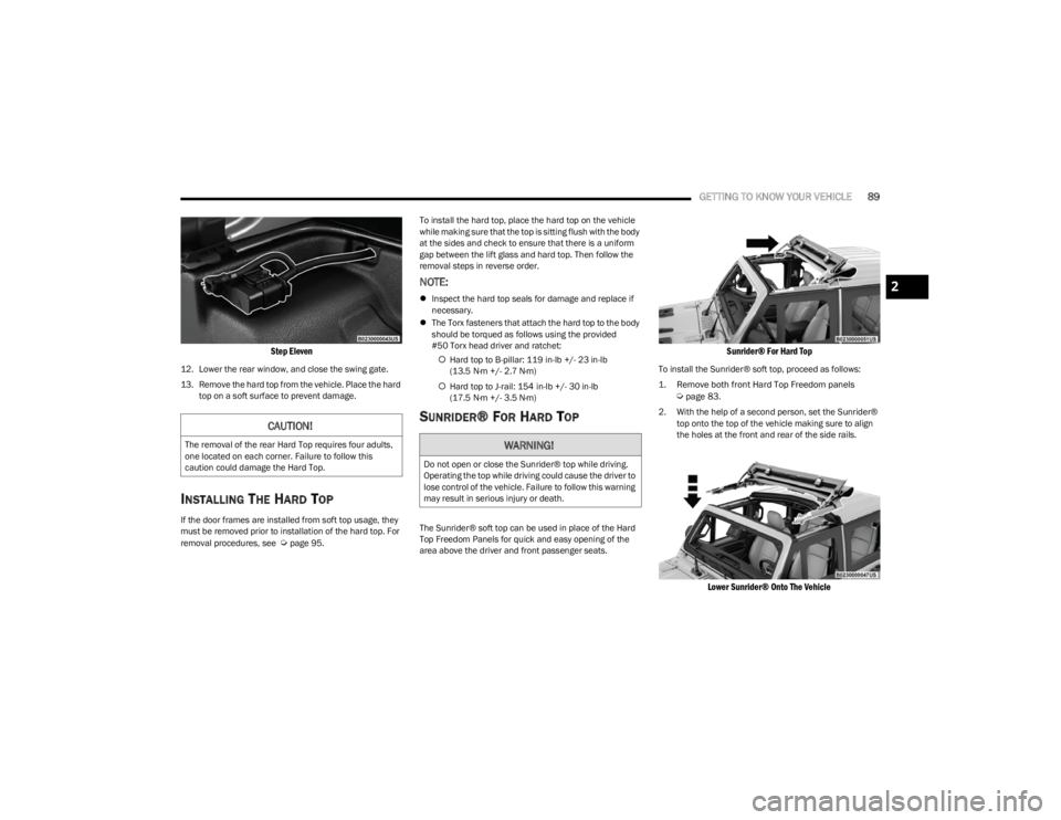
Step Eleven
12. Lower the rear window, and close the swing gate.
13. Remove the hard top from the vehicle. Place the hard
top on a soft surface to prevent damage.
INSTALLING THE HARD TOP
If the door frames are installed from soft top usage, they
must be removed prior to installation of the hard top. For
removal procedures, see
Úpage 95. To install the hard top, place the hard top on the vehicle
while making sure that the top is sitting flush with the body
at the sides and check to ensure that there is a uniform
gap between the lift glass and hard top. Then follow the
removal steps in reverse order.
NOTE:
Inspect the hard top seals for damage and replace if
necessary.
The Torx fasteners that attach the hard top to the body
should be torqued as follows using the provided
#50 Torx head driver and ratchet:
Hard top to B-pillar: 119 in-lb +/- 23 in-lb
(13.5 N·m +/- 2.7 N·m)
Hard top to J-rail: 154 in-lb +/- 30 in-lb
(17.5 N·m +/- 3.5 N·m)
SUNRIDER® FOR HARD TOP
The Sunrider® soft top can be used in place of the Hard
Top Freedom Panels for quick and easy opening of the
area above the driver and front passenger seats.
Sunrider® For Hard Top
To install the Sunrider® soft top, proceed as follows:
1. Remove both front Hard Top Freedom panels
Ú
page 83.
2. With the help of a second person, set the Sunrider® top onto the top of the vehicle making sure to align
the holes at the front and rear of the side rails.
Lower Sunrider® Onto The Vehicle
CAUTION!
The removal of the rear Hard Top requires four adults,
one located on each corner. Failure to follow this
caution could damage the Hard Top.WARNING!
Do not open or close the Sunrider® top while driving.
Operating the top while driving could cause the driver to
lose control of the vehicle. Failure to follow this warning
may result in serious injury or death.
2
23_JL_OM_EN_USC_t.book Page 89
Page 92 of 396
90GETTING TO KNOW YOUR VEHICLE
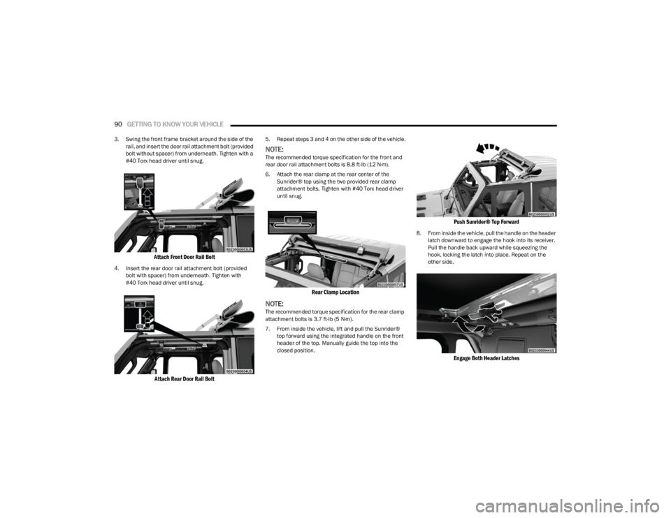
3. Swing the front frame bracket around the side of the
rail, and insert the door rail attachment bolt (provided
bolt without spacer) from underneath. Tighten with a
#40 Torx head driver until snug.
Attach Front Door Rail Bolt
4. Insert the rear door rail attachment bolt (provided bolt with spacer) from underneath. Tighten with
#40 Torx head driver until snug.
Attach Rear Door Rail Bolt
5. Repeat steps 3 and 4 on the other side of the vehicle.
NOTE:The recommended torque specification for the front and
rear door rail attachment bolts is 8.8 ft-lb (12 N·m).
6. Attach the rear clamp at the rear center of the Sunrider® top using the two provided rear clamp
attachment bolts. Tighten with #40 Torx head driver
until snug.
Rear Clamp Location
NOTE:The recommended torque specification for the rear clamp
attachment bolts is 3.7 ft-lb (5 N·m).
7. From inside the vehicle, lift and pull the Sunrider® top forward using the integrated handle on the front
header of the top. Manually guide the top into the
closed position.
Push Sunrider® Top Forward
8. From inside the vehicle, pull the handle on the header latch downward to engage the hook into its receiver.
Pull the handle back upward while squeezing the
hook, locking the latch into place. Repeat on the
other side.
Engage Both Header Latches
23_JL_OM_EN_USC_t.book Page 90
Page 93 of 396
GETTING TO KNOW YOUR VEHICLE91
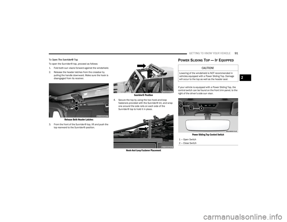
To Open The Sunrider® Top
To open the Sunrider® top, proceed as follows:
1. Fold both sun visors forward against the windshield.
2. Release the header latches from the crossbar by
pulling the handle downward. Make sure the hook is
disengaged from its receiver.
Release Both Header Latches
3. From the front of the Sunrider® top, lift and push the top rearward to the Sunrider® position.
Sunrider® Position
4. Secure the top by using the two hook-and-loop fasteners provided with the Sunrider® kit, and wrap
one around the side rails on each side of the
Sunrider® top to hold it in place.
Hook-And-Loop Fastener Placement
POWER SLIDING TOP — IF EQUIPPED
If your vehicle is equipped with a Power Sliding Top, the
control switch can be found on the front trim panel, to the
right of the driver’s side sun visor.
Power Sliding Top Control Switch
CAUTION!
Lowering of the windshield is NOT recommended in
vehicles equipped with a Power Sliding Top. Damage
will occur to the top as well as the header seal.
1 — Open Switch
2 — Close Switch
2
23_JL_OM_EN_USC_t.book Page 91
Page 94 of 396

92GETTING TO KNOW YOUR VEHICLE
(Continued)
NOTE:
The power top is non-removable. If desired, the rear
quarter windows can be removed and stored in the
provided storage bag
Úpage 93.
The power top will not open in temperatures below
-4°F (-20°C). However, if it is opened at a higher
temperature, it can be closed at temperatures above
-40°F (-40°C).
The power top will not operate at vehicle speeds above
60 mph (96 km/h).
NOTE:A slight pause in audio may be heard when opening and
closing the Power Sliding Top as a result of the Uconnect
system switching between power top Closed and power
top Open audio modes.
Opening And Closing The Power Top
Express Open/Close
Push the open switch and release it within one-half
second and the power top will open automatically from
any position. The power top will open fully and stop
automatically.
Push the close switch and release it within one-half
second and the power top will close automatically from
any position. The power top will close fully and stop
automatically.
During Express Open or Express Close operation, any
other movement of the power top switch will stop the
power top.
Manual Open/Close
To open the power top manually, push and hold the open
switch to the full open position, then release.
To close the power top manually, push and hold the close
switch to the fully closed position, then release.
Any release of the switch during open or close operation
will stop the power top movement. The top will remain in a
partially opened position until the switch is operated and
held again.
Pinch Protect Feature
This feature will detect an obstruction in the opening of
the power top during Express Close operation. If an
obstruction in the path of the power top is detected, the
power top will automatically retract. Remove the
obstruction if this occurs. Next, push the close switch and
release to Express Close.
NOTE:
The Power Sliding Top may reverse motion if closing
during a severe headwind. If this occurs, push and hold
the Power Sliding Top switch again to close the top
completely.
If three consecutive power top close attempts result in
Pinch Protect reversals, Pinch Protect will disable and
the power top must be closed in Manual Mode.
Power Top Maintenance
Use only a non-abrasive cleaner and a soft cloth to clean
the quarter window glass panel. For important information
on cleaning and caring for your vehicle
Úpage 360.
WARNING!
Never leave children unattended in a vehicle, or with
access to an unlocked vehicle. Never leave the key
fob in or near the vehicle, or in a location accessible
to children. Do not leave the Keyless Enter ‘n Go™
Ignition in the ACC or ON/RUN position. Occupants,
particularly unattended children, can become
entrapped by the power top while operating the
power top switch. Such entrapment may result in
serious injury or death.
In a collision, there is a greater risk of being thrown
from a vehicle with an open power top. You could
also be seriously injured or killed. Always fasten your
seat belt properly and make sure all passengers are
also properly secured.
Do not allow small children to operate the power top.
Never allow your fingers, other body parts, or any
object, to project through the power top opening.
Injury may result.
WARNING!
WARNING!
There is no anti-pinch protection when the power top is
almost closed. To avoid personal injury be sure to clear
your arms, hands, fingers and all objects from the top’s
path before closing.
23_JL_OM_EN_USC_t.book Page 92
Page 95 of 396
GETTING TO KNOW YOUR VEHICLE93
Ignition Off Operation
The power top switch can remain active in Accessory Delay
for up to approximately 10 minutes after the vehicle’s
ignition is placed to the OFF position. Opening either front
door will cancel this feature.
NOTE:Ignition Off time is programmable through the Uconnect
system Úpage 184.
Relearn Procedure
For vehicles equipped with a power top, there is a relearn
procedure that allows you to calibrate the power top when
the “Express Mode” stops working. To reset the power top,
follow these steps:
1. Place the ignition in the RUN position, and start the
vehicle.
NOTE:The engine must be running to perform the relearn
procedure.
2. Ensure the power top is in the fully closed position.
3. Push and hold the Close switch for 10 seconds. This will put the power top into calibration mode.
4. Continue holding down the close button while the top goes fully open and then back to fully close.
5. Once the power top has stopped in the fully closed position, release the close button. The power top is
now reset and ready to use.
NOTE:If the close button is released anytime during the
relearning process, the relearn may not be complete, and
the procedure must be repeated.
Rear Quarter Window Removal
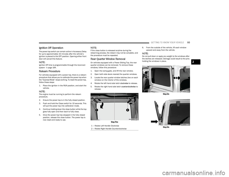
On vehicles equipped with a Power Sliding Top, the rear
quarter windows can be removed. To remove these
windows, follow this procedure:
1. Open the swing gate, and lift the rear window.
2. Open both side doors nearest the quarter windows.
3. Locate the rear quarter window latches (two on each window) on the interior of the windows.
4. Rotate the left hand side latch clockwise to release.
5. Rotate the right hand side latch counterclockwise to
release.
Step Five
6. From the outside of the vehicle, lift each window upward and away from the vehicle.
NOTE:Do not pull down or apply any weight to the windows after
the latches are released. Damage could result to the pins
holding the windows in place.
Step Six
Step Six
1 — Rotate Left Handle Clockwise
2 — Rotate Right Handle Counterclockwise
2
23_JL_OM_EN_USC_t.book Page 93
Page 96 of 396
94GETTING TO KNOW YOUR VEHICLE
7. Store the rear quarter windows in the provided
storage bag and keep in a safe location, or securely
fasten the bag to the rear seat.
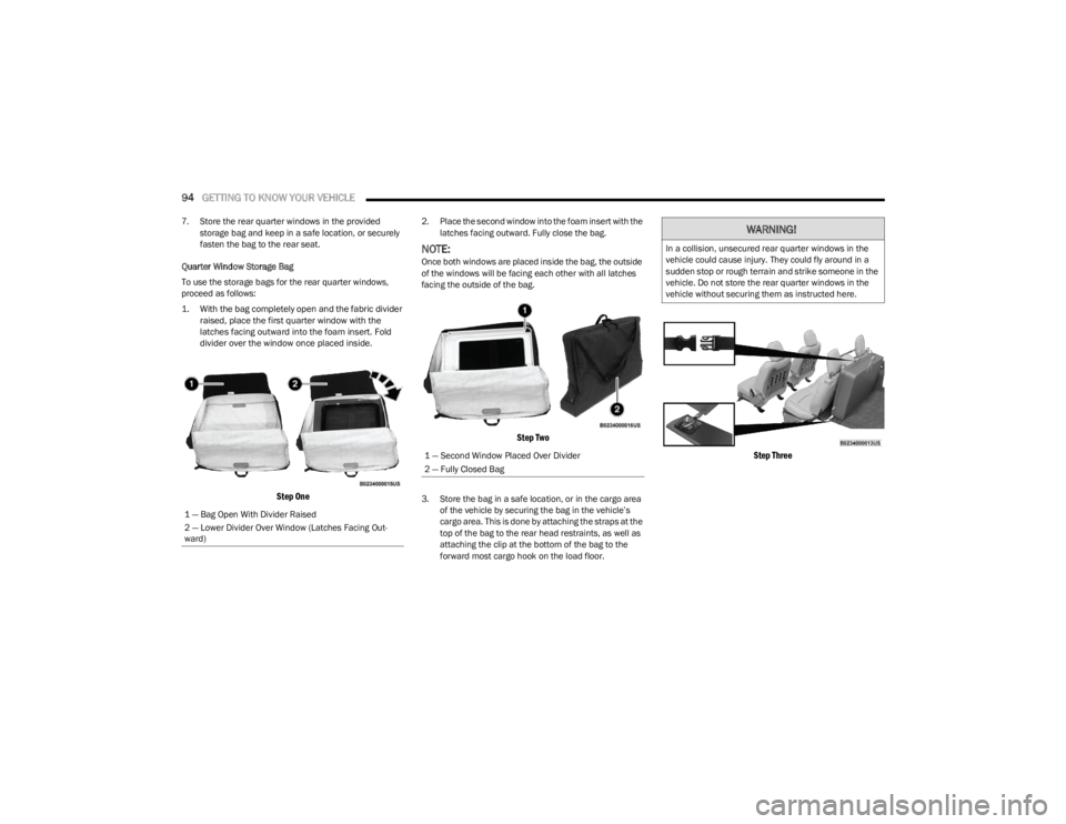
Quarter Window Storage Bag
To use the storage bags for the rear quarter windows,
proceed as follows:
1. With the bag completely open and the fabric divider raised, place the first quarter window with the
latches facing outward into the foam insert. Fold
divider over the window once placed inside.
Step One
2. Place the second window into the foam insert with the latches facing outward. Fully close the bag.
NOTE:Once both windows are placed inside the bag, the outside
of the windows will be facing each other with all latches
facing the outside of the bag.
Step Two
3. Store the bag in a safe location, or in the cargo area of the vehicle by securing the bag in the vehicle’s
cargo area. This is done by attaching the straps at the
top of the bag to the rear head restraints, as well as
attaching the clip at the bottom of the bag to the
forward most cargo hook on the load floor.
Step Three
1 — Bag Open With Divider Raised
2 — Lower Divider Over Window (Latches Facing Out -
ward)
1 — Second Window Placed Over Divider
2 — Fully Closed Bag
WARNING!
In a collision, unsecured rear quarter windows in the
vehicle could cause injury. They could fly around in a
sudden stop or rough terrain and strike someone in the
vehicle. Do not store the rear quarter windows in the
vehicle without securing them as instructed here.
23_JL_OM_EN_USC_t.book Page 94
Page 97 of 396
GETTING TO KNOW YOUR VEHICLE95
DOOR FRAME DOOR FRAME REMOVAL
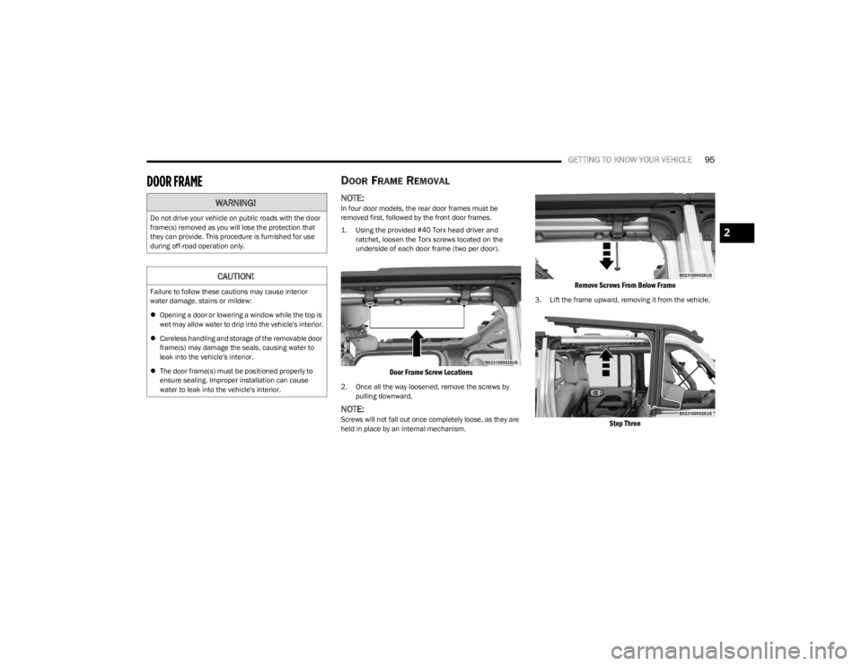
NOTE:In four door models, the rear door frames must be
removed first, followed by the front door frames.
1. Using the provided #40 Torx head driver and
ratchet, loosen the Torx screws located on the
underside of each door frame (two per door).
Door Frame Screw Locations
2. Once all the way loosened, remove the screws by pulling downward.
NOTE:Screws will not fall out once completely loose, as they are
held in place by an internal mechanism.
Remove Screws From Below Frame
3. Lift the frame upward, removing it from the vehicle.
Step Three
WARNING!
Do not drive your vehicle on public roads with the door
frame(s) removed as you will lose the protection that
they can provide. This procedure is furnished for use
during off-road operation only.
CAUTION!
Failure to follow these cautions may cause interior
water damage, stains or mildew:
Opening a door or lowering a window while the top is
wet may allow water to drip into the vehicle's interior.
Careless handling and storage of the removable door
frame(s) may damage the seals, causing water to
leak into the vehicle's interior.
The door frame(s) must be positioned properly to
ensure sealing. Improper installation can cause
water to leak into the vehicle's interior.
2
23_JL_OM_EN_USC_t.book Page 95
Page 98 of 396
96GETTING TO KNOW YOUR VEHICLE
4. Store screws in a secure location.
5. Repeat procedure on the front door frame (four door
models).
DOOR FRAME INSTALLATION FOUR
D
OOR MODELS — IF EQUIPPED
1. Install the front door rail first.
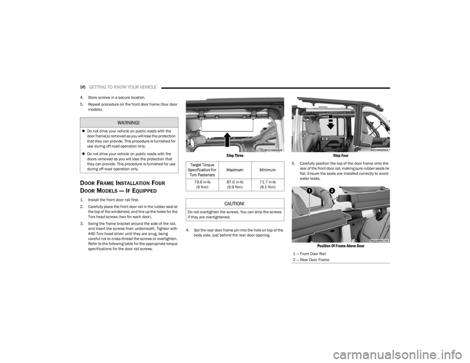
2. Carefully place the front door rail in the rubber seal at
the top of the windshield, and line up the holes for the
Torx head screws (two for each door).
3. Swing the frame bracket around the side of the rail, and insert the screws from underneath. Tighten with
#40 Torx head driver until they are snug, being
careful not to cross-thread the screws or overtighten.
Refer to the following table for the appropriate torque
specifications for the door rail screws.
Step Three
4. Set the rear door frame pin into the hole on top of the body side, just behind the rear door opening.
Step Four
5. Carefully position the top of the door frame onto the rear of the front door rail, making sure rubber seals lie
flat. Ensure the seals are installed correctly to avoid
water leaks.
Position Of Frame Above Door
WARNING!
Do not drive your vehicle on public roads with the
door frame(s) removed as you will lose the protection
that they can provide. This procedure is furnished for
use during off-road operation only.
Do not drive your vehicle on public roads with the
doors removed as you will lose the protection that
they can provide. This procedure is furnished for use
during off-road operation only.
Target Torque
Specification For Torx Fasteners Maximum Minimum
79.6 in-lb (9 N·m) 87.6 in-lb
(9.9 N·m) 71.7 in-lb
(8.1 N·m)
CAUTION!
Do not overtighten the screws. You can strip the screws
if they are overtightened.
1 — Front Door Rail
2 — Rear Door Frame
23_JL_OM_EN_USC_t.book Page 96
Page 99 of 396
GETTING TO KNOW YOUR VEHICLE97
(Continued)
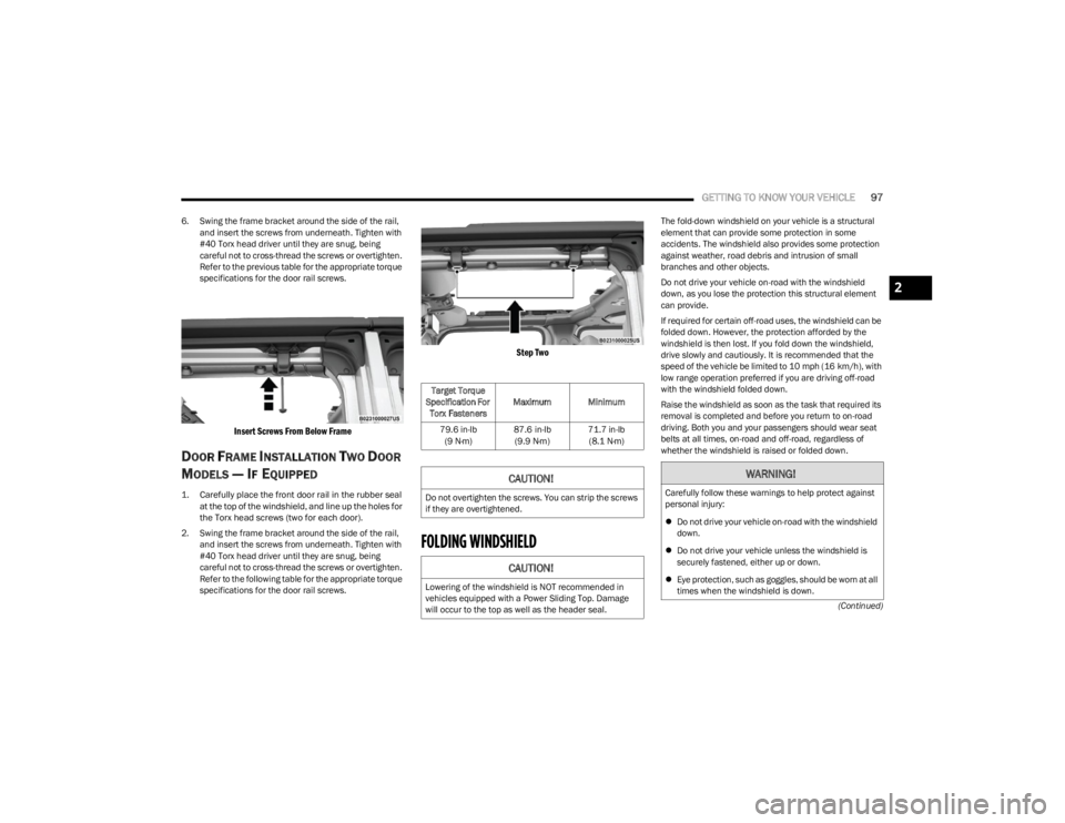
6. Swing the frame bracket around the side of the rail,
and insert the screws from underneath. Tighten with
#40 Torx head driver until they are snug, being
careful not to cross-thread the screws or overtighten.
Refer to the previous table for the appropriate torque
specifications for the door rail screws.
Insert Screws From Below Frame
DOOR FRAME INSTALLATION TWO DOOR
M
ODELS — IF EQUIPPED
1. Carefully place the front door rail in the rubber seal
at the top of the windshield, and line up the holes for
the Torx head screws (two for each door).
2. Swing the frame bracket around the side of the rail, and insert the screws from underneath. Tighten with
#40 Torx head driver until they are snug, being
careful not to cross-thread the screws or overtighten.
Refer to the following table for the appropriate torque
specifications for the door rail screws.
Step Two
FOLDING WINDSHIELD
The fold-down windshield on your vehicle is a structural
element that can provide some protection in some
accidents. The windshield also provides some protection
against weather, road debris and intrusion of small
branches and other objects.
Do not drive your vehicle on-road with the windshield
down, as you lose the protection this structural element
can provide.
If required for certain off-road uses, the windshield can be
folded down. However, the protection afforded by the
windshield is then lost. If you fold down the windshield,
drive slowly and cautiously. It is recommended that the
speed of the vehicle be limited to 10 mph (16 km/h), with
low range operation preferred if you are driving off-road
with the windshield folded down.
Raise the windshield as soon as the task that required its
removal is completed and before you return to on-road
driving. Both you and your passengers should wear seat
belts at all times, on-road and off-road, regardless of
whether the windshield is raised or folded down.
Target Torque
Specification For Torx Fasteners Maximum Minimum
79.6 in-lb (9 N·m) 87.6 in-lb
(9.9 N·m) 71.7 in-lb
(8.1 N·m)
CAUTION!
Do not overtighten the screws. You can strip the screws
if they are overtightened.
CAUTION!
Lowering of the windshield is NOT recommended in
vehicles equipped with a Power Sliding Top. Damage
will occur to the top as well as the header seal.
WARNING!
Carefully follow these warnings to help protect against
personal injury:
Do not drive your vehicle on-road with the windshield
down.
Do not drive your vehicle unless the windshield is
securely fastened, either up or down.
Eye protection, such as goggles, should be worn at all
times when the windshield is down.
2
23_JL_OM_EN_USC_t.book Page 97
Page 100 of 396
98GETTING TO KNOW YOUR VEHICLE
LOWERING THE WINDSHIELD
1. Before completing the following steps:
If your vehicle is equipped with a Soft Top, the top
MUST be lowered, and the door rails must be
removed prior to lowering the windshield.
If your vehicle is equipped with a Hard Top, the
Freedom Panels MUST be removed prior to
lowering the windshield.
Refer to the following instructions for more infor -
mation:
• Soft Top Lowering
Úpage 75
• Door Frame Úpage 95
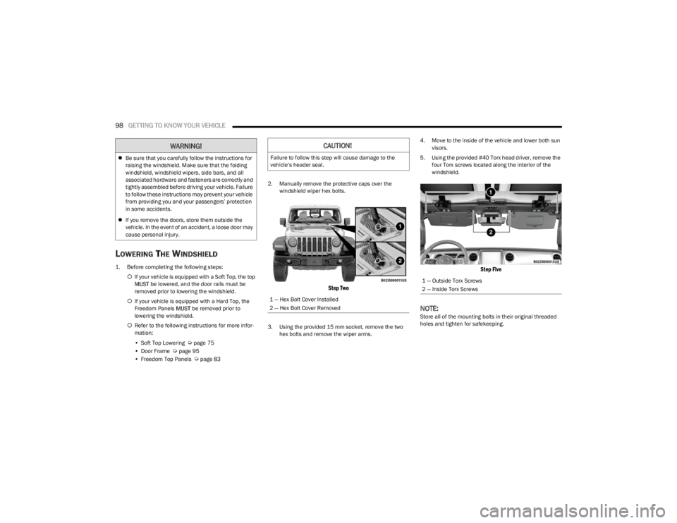
• Freedom Top Panels Úpage 83 2. Manually remove the protective caps over the
windshield wiper hex bolts.
Step Two
3. Using the provided 15 mm socket, remove the two hex bolts and remove the wiper arms. 4. Move to the inside of the vehicle and lower both sun
visors.
5. Using the provided #40 Torx head driver, remove the four Torx screws located along the interior of the
windshield.
Step Five
NOTE:Store all of the mounting bolts in their original threaded
holes and tighten for safekeeping.
Be sure that you carefully follow the instructions for
raising the windshield. Make sure that the folding
windshield, windshield wipers, side bars, and all
associated hardware and fasteners are correctly and
tightly assembled before driving your vehicle. Failure
to follow these instructions may prevent your vehicle
from providing you and your passengers’ protection
in some accidents.
If you remove the doors, store them outside the
vehicle. In the event of an accident, a loose door may
cause personal injury.
WARNING!CAUTION!
Failure to follow this step will cause damage to the
vehicle’s header seal.
1 — Hex Bolt Cover Installed
2 — Hex Bolt Cover Removed
1 — Outside Torx Screws
2 — Inside Torx Screws
23_JL_OM_EN_USC_t.book Page 98