warning light JEEP WRANGLER 2023 User Guide
[x] Cancel search | Manufacturer: JEEP, Model Year: 2023, Model line: WRANGLER, Model: JEEP WRANGLER 2023Pages: 396, PDF Size: 25.15 MB
Page 21 of 396
GETTING TO KNOW YOUR VEHICLE19
REMOTE START — IF EQUIPPED (DIESEL)
This system uses the key fob to start the engine
conveniently from outside the vehicle while still
maintaining security. The system has a range
of approximately 300 ft (91 m).
Remote Start is used to defrost windows in cold weather,
and to reach a comfortable climate in all ambient
conditions before the driver enters the vehicle.
NOTE:
The vehicle must be equipped with an automatic trans -
mission to be equipped with Remote Start.
Obstructions between the vehicle and the key fob may
reduce this range.
The Remote Start system will wait for the Wait To Start
Indicator Light
Úpage 116 to extinguish before
cranking the engine. This allows time for the engine
preheat cycle to heat the cylinder air, and is normal in
cold weather.
HOW TO USE REMOTE START
Push and release the Remote Start button on the key fob
twice within five seconds. The vehicle doors and swing
gate will lock, the turn signals will flash twice, and the horn
will chirp twice. Pushing the Remote Start button again will
shut the engine off.
NOTE:
With Remote Start, the engine will only run for
15 minutes.
Remote Start can only be used twice.
If an engine fault is present or fuel level is low, the
vehicle will start and then shut down in 10 seconds.
The park lamps will turn on and remain on during
Remote Start mode.
For security, power window operation is disabled when
the vehicle is in the Remote Start mode.
The ignition must be placed in the ON/RUN position
before the Remote Start sequence can be repeated for
a third cycle.
All of the following conditions must be met before the
engine will remote start:
Gear selector in PARK
Doors closed
Hood closed
Swing gate closed
Hazard switch off
Brake switch inactive (brake pedal not pressed)
Battery at an acceptable charge level
Panic button not pushed
Fuel meets minimum requirement
System not disabled from previous Remote Start event
Vehicle Security system not active
Malfunction Indicator Light (MIL) is not illuminated
Water In Fuel Indicator Light is not illuminated
Wait To Start Indicator Light is not illuminated
For additional Remote Start information, see
Úpage 18.
VEHICLE SECURITY SYSTEM — IF EQUIPPED
The Vehicle Security system monitors the vehicle doors for
unauthorized entry and the ignition switch for
unauthorized operation. When the alarm is activated, the
interior switches for door locks are disabled. The Vehicle
Security system provides both audible and visible signals.
If something triggers the alarm, the Vehicle Security
system will provide the following audible and visible
signals: the horn will pulse, the park lamps and/or turn
signals will flash, and the Vehicle Security Light in the
instrument cluster will flash.WARNING!
Do not start or run an engine in a closed garage or
confined area. Exhaust gas contains carbon
monoxide (CO) which is odorless and colorless.
Carbon monoxide is poisonous and can cause
serious injury or death when inhaled.
Keep key fobs away from children. Operation of the
Remote Start system, windows, door locks or other
controls could cause serious injury or death.
WARNING!
Do not start or run an engine in a closed garage or
confined area. Exhaust gas contains carbon
monoxide (CO) which is odorless and colorless.
Carbon monoxide is poisonous and can cause
serious injury or death when inhaled.
Keep key fobs away from children. Operation of the
Remote Start system, windows, door locks or other
controls could cause serious injury or death.2
23_JL_OM_EN_USC_t.book Page 19
Page 29 of 396
GETTING TO KNOW YOUR VEHICLE27
Replacing The Wiring Connector Into The Wiring Harness
To reinstall the wiring connector on the vehicle’s door into
the harness just inside the vehicle, proceed as follows:
NOTE:Make sure there is plenty of slack on the wiring connector
during installation. Close the door slightly to provide more
slack if needed.
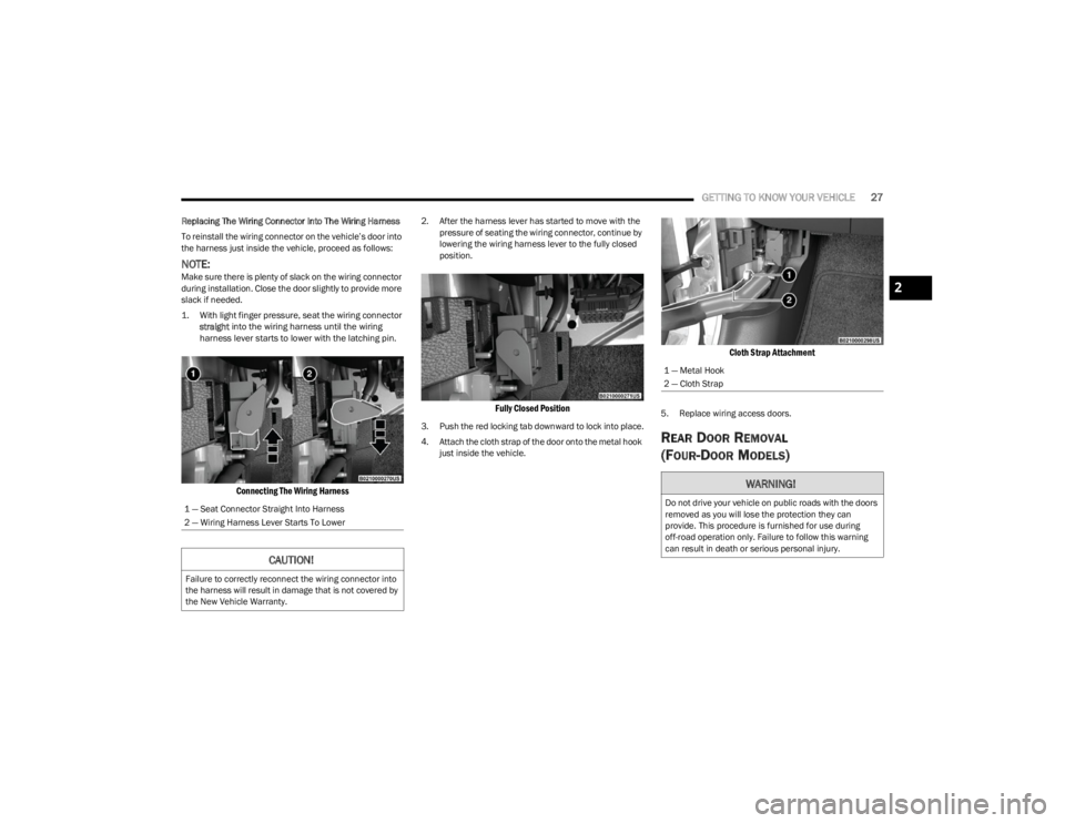
1. With light finger pressure, seat the wiring connector
straight
into the wiring harness until the wiring
harness lever starts to lower with the latching pin.
Connecting The Wiring Harness
2. After the harness lever has started to move with the pressure of seating the wiring connector, continue by
lowering the wiring harness lever to the fully closed
position.
Fully Closed Position
3. Push the red locking tab downward to lock into place.
4. Attach the cloth strap of the door onto the metal hook just inside the vehicle.
Cloth Strap Attachment
5. Replace wiring access doors.
REAR DOOR REMOVAL
(FOUR-DOOR MODELS)
1 — Seat Connector Straight Into Harness
2 — Wiring Harness Lever Starts To Lower
CAUTION!
Failure to correctly reconnect the wiring connector into
the harness will result in damage that is not covered by
the New Vehicle Warranty.
1 — Metal Hook
2 — Cloth Strap
WARNING!
Do not drive your vehicle on public roads with the doors
removed as you will lose the protection they can
provide. This procedure is furnished for use during
off-road operation only. Failure to follow this warning
can result in death or serious personal injury.
2
23_JL_OM_EN_USC_t.book Page 27
Page 48 of 396
46GETTING TO KNOW YOUR VEHICLE
ILLUMINATED VANITY MIRRORS
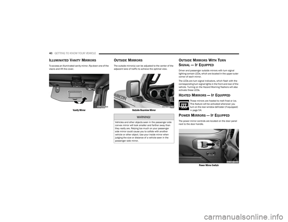
To access an illuminated vanity mirror, flip down one of the
visors and lift the cover.
Vanity Mirror
OUTSIDE MIRRORS
The outside mirror(s) can be adjusted to the center of the
adjacent lane of traffic to achieve the optimal view.
Outside Rearview Mirror
OUTSIDE MIRRORS WITH TURN
SIGNAL — IF EQUIPPED
Driver and passenger outside mirrors with turn signal
lighting contain LEDs, which are located in the upper outer
corner of each mirror.
The LEDs are turn signal indicators, which flash with the
corresponding turn signal lights in the front and rear of the
vehicle. Turning on the Hazard Warning flashers will also
activate these LEDs.
HEATED MIRRORS — IF EQUIPPED
These mirrors are heated to melt frost or ice.
This feature will be activated whenever you
turn on the rear window defroster (if equipped)
Úpage 54.
POWER MIRRORS — IF EQUIPPED
The power mirror controls are located on the door panel
next to the door handle.
Power Mirror Switch
WARNING!
Vehicles and other objects seen in the passenger side
convex mirror will look smaller and farther away than
they really are. Relying too much on your passenger
side mirror could cause you to collide with another
vehicle or other object. Use your inside mirror when
judging the size or distance of a vehicle seen in the
passenger side mirror.
23_JL_OM_EN_USC_t.book Page 46
Page 50 of 396
48GETTING TO KNOW YOUR VEHICLE
NOTE:The “LEARN” or “TRAIN” button is not the button you
normally use to operate the device.
Non-rolling Code Devices
Most devices manufactured before 1995 will not have a
rolling code. These devices will also not have a “LEARN” or
“TRAIN” button.
PROGRAMMING HOMELINK® TO A
G
ARAGE DOOR OPENER
To program any of the HomeLink® buttons to activate your
garage door opener motor, refer to the following steps:
NOTE:All HomeLink® buttons are programmed using this
procedure. You do not need to erase all channels when
programming additional buttons.
1. Place the ignition switch in the ON/RUN position.
2. Place the garage door opener transmitter 1 to
3 inches (3 to 8 cm) away from the HomeLink®
button you wish to program, while keeping the
HomeLink® indicator light in view.
3. Push and hold the HomeLink® button you want to program while you push and hold the garage door
opener transmitter button you are trying to replicate.
4. Continue to hold both buttons and observe the HomeLink® indicator light. The HomeLink® indicator
light will flash slowly and then rapidly. Once this
happens, release both buttons.
NOTE:Make sure the garage door opener motor is plugged in
before moving on to the rolling code/non-rolling code final
steps.
Rolling Code Garage Door Opener Final Steps
NOTE:You have 30 seconds in which to initiate rolling code final
step 2, after completing rolling code final step 1.
1. At the garage door opener motor (in the garage), locate the “LEARN” or “TRAIN” button. This can
usually be found where the hanging antenna wire is
attached to the garage door opener motor. Firmly
push and release the “LEARN” or “TRAIN” button.
2. Return to the vehicle and push the programmed HomeLink® button three times (holding the button
for two seconds each time). If the garage door opener
motor operates, programming is complete.
3. Push the programmed HomeLink® button to confirm that the garage door opener motor operates. If the
garage door opener motor does not operate, repeat
the final steps for the rolling code procedure.
Non-Rolling Code Garage Door Opener Final Steps
1. Push and hold the programmed HomeLink® button and observe the HomeLink® indicator light. If the
HomeLink® indicator light stays on constantly,
programming is complete.
2. Push the programmed HomeLink® button to confirm that the garage door opener motor operates. If the
garage door opener motor does not operate, repeat
the steps from the beginning.
PROGRAMMING HOMELINK® TO A
M
ISCELLANEOUS DEVICE
The procedure on how to program HomeLink® to a
miscellaneous device follows the same procedure as
programming to a garage door opener
Úpage 48. Be sure
to determine if the device has a rolling code, or non-rolling
code before beginning the programming process.
NOTE:Canadian radio frequency laws require transmitter signals
to time-out (or quit) after several seconds of transmission,
which may not be long enough for HomeLink® to pick up
the signal during programming. Similar to this Canadian
law, some US gate operators are designed to time-out in
the same manner. The procedure may need to be
performed multiple times to successfully pair the device to
your HomeLink® buttons.
WARNING!
Your motorized door or gate will open and close while
you are programming the universal transceiver. Do
not program the transceiver if people or pets are in
the path of the door or gate.
Do not run your vehicle in a closed garage or
confined area while programming the transceiver.
Exhaust gas from your vehicle contains Carbon
Monoxide (CO) which is odorless and colorless.
Carbon Monoxide is poisonous when inhaled and
can cause you and others to be severely injured or
killed.
23_JL_OM_EN_USC_t.book Page 48
Page 52 of 396
50GETTING TO KNOW YOUR VEHICLE
TROUBLESHOOTING TIPS
If you are having trouble programming HomeLink®, here
are some of the most common solutions:
Replace the battery in the garage door opener
hand-held transmitter.
Push the LEARN button on the garage door opener to
complete the training for a rolling code.
Did you unplug the device for programming and
remember to plug it back in?
If you have any problems, or require assistance, please
call toll-free 1-800-355-3515 or, on the Internet at
HomeLink.com for information or assistance.
EXTERIOR LIGHTS
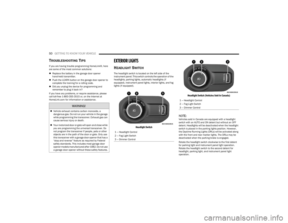
HEADLIGHT SWITCH
The headlight switch is located on the left side of the
instrument panel. This switch controls the operation of the
headlights, parking lights, automatic headlights (if
equipped), instrument panel lights, interior lights, and fog
lights (if equipped).
Headlight Switch Headlight Switch (Vehicles Sold In Canada)
NOTE:Vehicles sold in Canada are equipped with a headlight
switch with an AUTO and ON detent but without an OFF
detent. Headlights will be deactivated when the headlight
switch is placed in the parking lights position. However,
the Daytime Running Lights (DRLs) will be activated along
with the front and rear marker lights. The DRLs may be
deactivated when the parking brake is engaged.
Rotate the headlight switch clockwise to the first detent
for parking light and instrument panel light operation.
Rotate the headlight switch to the second detent for
headlight, parking light, and instrument panel light
operation.
WARNING!
Vehicle exhaust contains carbon monoxide, a
dangerous gas. Do not run your vehicle in the garage
while programming the transceiver. Exhaust gas can
cause serious injury or death.
Your motorized door or gate will open and close while
you are programming the universal transceiver. Do
not program the transceiver if people, pets or other
objects are in the path of the door or gate. Only use
this transceiver with a garage door opener that has a
“stop and reverse” feature as required by Federal
safety standards. This includes most garage door
opener models manufactured after 1982. Do not use
a garage door opener without these safety features.
1 — Headlight Control
2 — Fog Light Switch
3 — Dimmer Control
1 — Headlight Control
2 — Fog Light Switch
3 — Dimmer Control
23_JL_OM_EN_USC_t.book Page 50
Page 53 of 396
GETTING TO KNOW YOUR VEHICLE51
NOTE:For vehicles sold in Canada, rotate the headlight switch
clockwise from the parking lights and instrument panel
lights position to the first detent to turn on headlights,
parking lights, and instrument panel lights. Rotate the
headlight switch to the second detent for the AUTO
position.
DAYTIME RUNNING LIGHTS (DRLS) —
I
F EQUIPPED
The Daytime Running Lights are active when the low
beams are not on, and the engine is running. DRLs may be
deactivated by applying the parking brake.
NOTE:
For vehicles sold in Canada, the Daytime Running
Lights will automatically deactivate when the front fog
lights are turned on.
On some vehicles, the Daytime Running Lights may
deactivate, or reduce intensity, on one side of the
vehicle (when a turn signal is activated on that side), or
on both sides of the vehicle (when the hazard warning
lights are activated).
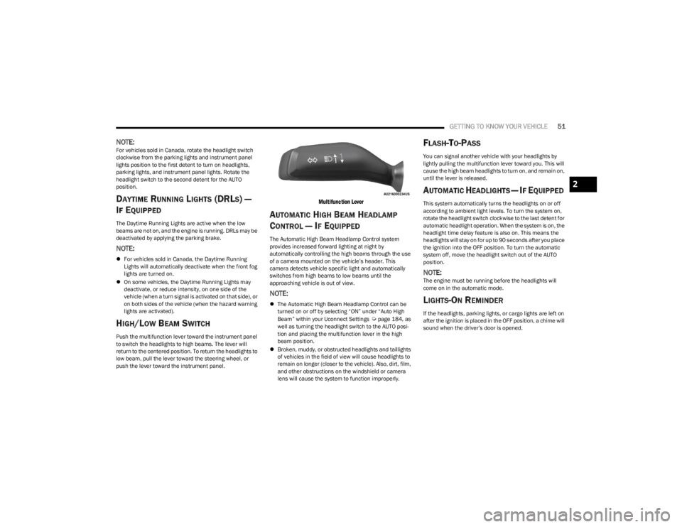
HIGH/LOW BEAM SWITCH
Push the multifunction lever toward the instrument panel
to switch the headlights to high beams. The lever will
return to the centered position. To return the headlights to
low beam, pull the lever toward the steering wheel, or
push the lever toward the instrument panel.
Multifunction Lever
AUTOMATIC HIGH BEAM HEADLAMP
C
ONTROL — IF EQUIPPED
The Automatic High Beam Headlamp Control system
provides increased forward lighting at night by
automatically controlling the high beams through the use
of a camera mounted on the vehicle’s header. This
camera detects vehicle specific light and automatically
switches from high beams to low beams until the
approaching vehicle is out of view.
NOTE:
The Automatic High Beam Headlamp Control can be
turned on or off by selecting “ON” under “Auto High
Beam” within your Uconnect Settings
Úpage 184, as
well as turning the headlight switch to the AUTO posi -
tion and placing the multifunction lever in the high
beam position.
Broken, muddy, or obstructed headlights and taillights
of vehicles in the field of view will cause headlights to
remain on longer (closer to the vehicle). Also, dirt, film,
and other obstructions on the windshield or camera
lens will cause the system to function improperly.
FLASH-TO-PASS
You can signal another vehicle with your headlights by
lightly pulling the multifunction lever toward you. This will
cause the high beam headlights to turn on, and remain on,
until the lever is released.
AUTOMATIC HEADLIGHTS — IF EQUIPPED
This system automatically turns the headlights on or off
according to ambient light levels. To turn the system on,
rotate the headlight switch clockwise to the last detent for
automatic headlight operation. When the system is on, the
headlight time delay feature is also on. This means the
headlights will stay on for up to 90 seconds after you place
the ignition into the OFF position. To turn the automatic
system off, move the headlight switch out of the AUTO
position.
NOTE:The engine must be running before the headlights will
come on in the automatic mode.
LIGHTS-ON REMINDER
If the headlights, parking lights, or cargo lights are left on
after the ignition is placed in the OFF position, a chime will
sound when the driver’s door is opened.
2
23_JL_OM_EN_USC_t.book Page 51
Page 65 of 396
GETTING TO KNOW YOUR VEHICLE63
(Continued)
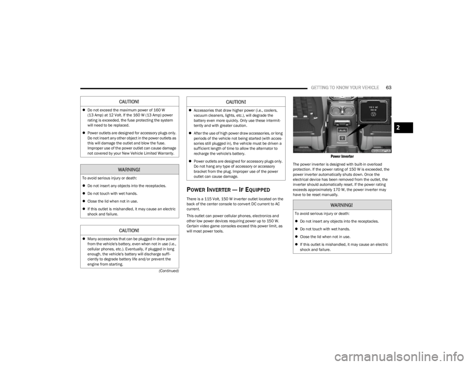
POWER INVERTER — IF EQUIPPED
There is a 115 Volt, 150 W inverter outlet located on the
back of the center console to convert DC current to AC
current.
This outlet can power cellular phones, electronics and
other low power devices requiring power up to 150 W.
Certain video game consoles exceed this power limit, as
will most power tools.
Power Inverter
The power inverter is designed with built-in overload
protection. If the power rating of 150 W is exceeded, the
power inverter automatically shuts down. Once the
electrical device has been removed from the outlet, the
inverter should automatically reset. If the power rating
exceeds approximately 170 W, the power inverter may
have to be reset manually.
CAUTION!
Do not exceed the maximum power of 160 W
(13 Amp) at 12 Volt. If the 160 W (13 Amp) power
rating is exceeded, the fuse protecting the system
will need to be replaced.
Power outlets are designed for accessory plugs only.
Do not insert any other object in the power outlets as
this will damage the outlet and blow the fuse.
Improper use of the power outlet can cause damage
not covered by your New Vehicle Limited Warranty.
WARNING!
To avoid serious injury or death:
Do not insert any objects into the receptacles.
Do not touch with wet hands.
Close the lid when not in use.
If this outlet is mishandled, it may cause an electric
shock and failure.
CAUTION!
Many accessories that can be plugged in draw power
from the vehicle's battery, even when not in use (i.e.,
cellular phones, etc.). Eventually, if plugged in long
enough, the vehicle's battery will discharge suffi -
ciently to degrade battery life and/or prevent the
engine from starting.
Accessories that draw higher power (i.e., coolers,
vacuum cleaners, lights, etc.), will degrade the
battery even more quickly. Only use these intermit -
tently and with greater caution.
After the use of high power draw accessories, or long
periods of the vehicle not being started (with acces -
sories still plugged in), the vehicle must be driven a
sufficient length of time to allow the alternator to
recharge the vehicle's battery.
Power outlets are designed for accessory plugs only.
Do not hang any type of accessory or accessory
bracket from the plug. Improper use of the power
outlet can cause damage.
CAUTION!
WARNING!
To avoid serious injury or death:
Do not insert any objects into the receptacles.
Do not touch with wet hands.
Close the lid when not in use.
If this outlet is mishandled, it may cause an electric
shock and failure.
2
23_JL_OM_EN_USC_t.book Page 63
Page 94 of 396
92GETTING TO KNOW YOUR VEHICLE
(Continued)
NOTE:
The power top is non-removable. If desired, the rear
quarter windows can be removed and stored in the
provided storage bag
Úpage 93.
The power top will not open in temperatures below
-4°F (-20°C). However, if it is opened at a higher
temperature, it can be closed at temperatures above
-40°F (-40°C).
The power top will not operate at vehicle speeds above
60 mph (96 km/h).
NOTE:A slight pause in audio may be heard when opening and
closing the Power Sliding Top as a result of the Uconnect
system switching between power top Closed and power
top Open audio modes.
Opening And Closing The Power Top
Express Open/Close
Push the open switch and release it within one-half
second and the power top will open automatically from
any position. The power top will open fully and stop
automatically.
Push the close switch and release it within one-half
second and the power top will close automatically from
any position. The power top will close fully and stop
automatically.
During Express Open or Express Close operation, any
other movement of the power top switch will stop the
power top.
Manual Open/Close
To open the power top manually, push and hold the open
switch to the full open position, then release.
To close the power top manually, push and hold the close
switch to the fully closed position, then release.
Any release of the switch during open or close operation
will stop the power top movement. The top will remain in a
partially opened position until the switch is operated and
held again.
Pinch Protect Feature
This feature will detect an obstruction in the opening of
the power top during Express Close operation. If an
obstruction in the path of the power top is detected, the
power top will automatically retract. Remove the
obstruction if this occurs. Next, push the close switch and
release to Express Close.
NOTE:
The Power Sliding Top may reverse motion if closing
during a severe headwind. If this occurs, push and hold
the Power Sliding Top switch again to close the top
completely.
If three consecutive power top close attempts result in
Pinch Protect reversals, Pinch Protect will disable and
the power top must be closed in Manual Mode.
Power Top Maintenance
Use only a non-abrasive cleaner and a soft cloth to clean
the quarter window glass panel. For important information
on cleaning and caring for your vehicle
Úpage 360.
WARNING!
Never leave children unattended in a vehicle, or with
access to an unlocked vehicle. Never leave the key
fob in or near the vehicle, or in a location accessible
to children. Do not leave the Keyless Enter ‘n Go™
Ignition in the ACC or ON/RUN position. Occupants,
particularly unattended children, can become
entrapped by the power top while operating the
power top switch. Such entrapment may result in
serious injury or death.
In a collision, there is a greater risk of being thrown
from a vehicle with an open power top. You could
also be seriously injured or killed. Always fasten your
seat belt properly and make sure all passengers are
also properly secured.
Do not allow small children to operate the power top.
Never allow your fingers, other body parts, or any
object, to project through the power top opening.
Injury may result.
WARNING!
WARNING!
There is no anti-pinch protection when the power top is
almost closed. To avoid personal injury be sure to clear
your arms, hands, fingers and all objects from the top’s
path before closing.
23_JL_OM_EN_USC_t.book Page 92
Page 103 of 396
GETTING TO KNOW YOUR VEHICLE101
NOTE:
Vehicle must be at a stop and the gear selector must
be in PARK.
You may have to push down slightly on the hood before
pushing the safety latch.
While lifting the hood, use both hands.
Before lifting the hood, check that the wiper arms are
not in motion and not in the lifted position.
CLOSING THE HOOD
If applicable, refer to the “Hybrid Supplement” for
additional information.
To close the hood, remove the support rod from the slot
and replace it on the hood panel retaining clip. Lower the
hood slowly. Secure both of the hood latches.
REAR SWING GATE
The rear swing gate can be unlocked by using one of the
following methods:
Mechanical key (with mechanical lock — if equipped)
Remote Keyless Entry key fob (if equipped)
Power door unlock switch on the front doors (if
equipped)
Passive Entry swing gate handle (if equipped)
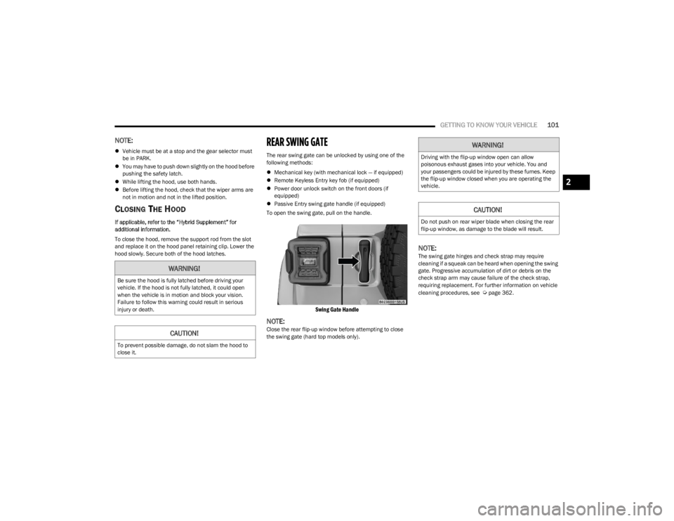
To open the swing gate, pull on the handle.
Swing Gate Handle
NOTE:Close the rear flip-up window before attempting to close
the swing gate (hard top models only).
NOTE:The swing gate hinges and check strap may require
cleaning if a squeak can be heard when opening the swing
gate. Progressive accumulation of dirt or debris on the
check strap arm may cause failure of the check strap,
requiring replacement. For further information on vehicle
cleaning procedures, see
Úpage 362.
WARNING!
Be sure the hood is fully latched before driving your
vehicle. If the hood is not fully latched, it could open
when the vehicle is in motion and block your vision.
Failure to follow this warning could result in serious
injury or death.
CAUTION!
To prevent possible damage, do not slam the hood to
close it.
WARNING!
Driving with the flip-up window open can allow
poisonous exhaust gases into your vehicle. You and
your passengers could be injured by these fumes. Keep
the flip-up window closed when you are operating the
vehicle.
CAUTION!
Do not push on rear wiper blade when closing the rear
flip-up window, as damage to the blade will result.
2
23_JL_OM_EN_USC_t.book Page 101
Page 112 of 396
110GETTING TO KNOW YOUR INSTRUMENT PANEL
OIL CHANGE RESET — IF EQUIPPED
Use this QR code to access your digital
experience.
Your vehicle may be equipped with an
engine oil change indicator system.
The “Oil Change Required” message
will display in the instrument cluster
display for five seconds after a single
chime has sounded to indicate the next
scheduled oil change interval. The engine oil change
indicator system is duty cycle based, which means the
engine oil change interval may fluctuate, dependent upon
your personal driving style.
Unless reset, this message will continue to display each
time you place the ignition in the ON/RUN position. To turn
off the message temporarily, push and release the OK
button. To reset the oil change indicator system (after
performing the scheduled maintenance), refer to the
following procedure.
Oil Life Reset
1. Without pushing the brake pedal, place the ignition in the ON/RUN mode (do not start the engine).
2. Navigate to "Oil Life" submenu in "Vehicle Info" in the instrument cluster display.
3. Push and hold the OK button until the gauge resets to
100%. Secondary Method For Oil Change Reset Procedure
1. Without pushing the brake pedal, place the ignition
in the ON/RUN position (do not start the engine).
2. Fully press the accelerator pedal, slowly, three times within ten seconds.
3. Without pushing the brake pedal, place the ignition in the OFF position.
NOTE:If the indicator message illuminates when you start the
vehicle, the oil change indicator system did not reset. If
necessary, repeat this procedure.
DISPLAY AND MESSAGES
The instrument cluster display is located in the center
portion of the cluster and consist of multiple sections:
Main Screen — The inner ring of the display will illumi -
nate in black under normal conditions, yellow for non
critical warnings and red for critical warnings
Submenu Dots — Whenever there are submenus avail -
able, the position within the submenus is shown here
Reconfigurable Telltales/Information
Gear Selector Status (PRND)
Driver Interactive Display (Compass, Temp, Range to
Empty, Trip A, Trip B, Average Fuel Economy, Current
Fuel Economy and Time)
Four Wheel Drive (4WD) Status — If Equipped The instrument cluster display will normally display the
main menu or the screens of a selected feature of the
main menu. The main display area also displays pop-up
messages and warning or information messages. These
pop-up messages fall into several categories:
Five Second Stored Messages
When the appropriate conditions occur, this type of
message takes control of the main display area for five
seconds and then returns to the previous screen. Most
of the messages of this type are then stored (as long as
the condition that activated it remains active) and can
be reviewed from the “Messages” main menu item.
Examples of this message type are “Right Front Turn
Signal Lamp Out” and “Low Tire Pressure”.
Unstored Messages
This message type is displayed indefinitely or until the
condition that activated the message is cleared. Exam -
ples of this message type are “Turn Signal On” (if a turn
signal is left on) and “Lights On” (if driver leaves the
vehicle with the lights on).
Unstored Messages Until RUN
These messages deal primarily with the Remote Start
feature. This message type is displayed until the igni -
tion is in the RUN state. Examples of this message type
are “Remote Start Canceled - Door Ajar” and “Press
Brake Pedal and Push Button to Start”.
Five Second Unstored Messages
When the appropriate conditions occur, this type of
message takes control of the main display area for five
seconds and then returns to the previous screen. An
example of this message type is “Automatic High
Beams On”.
23_JL_OM_EN_USC_t.book Page 110