fuse JEEP WRANGLER 2023 Owners Manual
[x] Cancel search | Manufacturer: JEEP, Model Year: 2023, Model line: WRANGLER, Model: JEEP WRANGLER 2023Pages: 396, PDF Size: 25.15 MB
Page 8 of 396
6
VEHICLE MAINTENANCE ................................................ 318
Engine Oil................................................................... 318
Engine Oil Filter ......................................................... 319
Engine Air Cleaner Filter ........................................... 319
Draining Fuel/Water Separator Filter —
Diesel Engine............................................................. 321Fuel Filter Replacement — Diesel Engine................ 321
Priming If The Engine Has Run Out Of Fuel —
Diesel Engine ............................................................ 323
Intervention Regeneration Strategy —
Message Process Flow ............................................ 323
Diesel Exhaust Fluid ................................................. 323
Accessory Drive Belt Inspection ............................... 324
Air Conditioner Maintenance ................................... 324
Body Lubrication ....................................................... 326Windshield Wiper Blades.......................................... 326
Exhaust System ........................................................ 328
Cooling System.......................................................... 328
Brake System ........................................................... 331
Front/Rear Axle Fluid ............................................... 332Transfer Case ........................................................... 332
Manual Transmission — If Equipped ....................... 332
Automatic Transmission — If Equipped .................. 333Fuses ........................................................................ 333
Bulb Replacement .................................................... 342
TIRES ................................................................................ 345 Tire Safety Information ............................................. 345
Tires — General Information ..................................... 352
Tire Types................................................................... 355
Spare Tires — If Equipped ........................................ 355Wheel And Wheel Trim Care ..................................... 356
Snow Traction Devices ............................................ 357
Tire Rotation Recommendations ............................ 358 DEPARTMENT OF TRANSPORTATION UNIFORM
TIRE QUALITY GRADES .................................................. 358
Treadwear ................................................................. 358Traction Grades ........................................................ 359Temperature Grades ................................................ 359
STORING THE VEHICLE ................................................... 359
BODYWORK ...................................................................... 360 Protection From Atmospheric Agents ...................... 360Body And Underbody Maintenance ......................... 361
Preserving The Bodywork ......................................... 361
INTERIORS ....................................................................... 362 Carpet Safety Information ........................................ 362
Carpet Removal ........................................................ 363Seats And Fabric Parts ............................................. 367
Plastic And Coated Parts .......................................... 367Leather Surfaces ...................................................... 367
Glass Surfaces ......................................................... 367
TECHNICAL SPECIFICATIONS
VEHICLE IDENTIFICATION NUMBER (VIN)..................... 368
BRAKE SYSTEM ............................................................... 368
WHEEL AND TIRE TORQUE SPECIFICATIONS .............. 368 Torque Specifications ............................................... 368
FUEL REQUIREMENTS — GASOLINE ENGINE ............... 369 2.0L Engine ............................................................... 3693.6L Engine ............................................................... 369Reformulated Gasoline ............................................ 369
Materials Added To Fuel .......................................... 369Gasoline/Oxygenate Blends ................................... 370Do Not Use E-85 In Non-Flex Fuel Vehicles ............ 370
CNG And LP Fuel System Modifications.................. 370
MMT In Gasoline ....................................................... 370
Fuel System Cautions ............................................... 370 FUEL REQUIREMENTS – DIESEL ENGINE ..................... 371
Diesel Fuel Specifications ........................................ 371Biodiesel Fuel Requirements ................................... 371
FLUID CAPACITIES ...........................................................373
ENGINE FLUIDS AND LUBRICANTS ................................374
CHASSIS FLUIDS AND LUBRICANTS ............................. 376
CUSTOMER ASSISTANCE
SUGGESTIONS FOR OBTAINING SERVICE FOR
YOUR VEHICLE ................................................................. 377 Prepare For The Appointment .................................. 377
Prepare A List ............................................................ 377Be Reasonable With Requests ................................. 377
IF YOU NEED ASSISTANCE .............................................377 Roadside Assistance ................................................. 377
FCA US LLC Customer Center ................................... 378
FCA Canada Inc. Customer Center........................... 378
Mexico ........................................................................ 378
Puerto Rico And US Virgin Islands............................ 378
Customer Assistance For The Hearing Or
Speech Impaired
(TDD/TTY)................................................................... 379Service Contract ....................................................... 379
WARRANTY INFORMATION.............................................379
MOPAR® PARTS ..............................................................379
REPORTING SAFETY DEFECTS ......................................379 In The 50 United States And Washington, D.C........ 379
In Canada................................................................... 380
PUBLICATION ORDER FORMS .......................................380
CHANGE OF OWNERSHIP OR ADDRESS.......................380
GENERAL INFORMATION................................................. 381
23_JL_OM_EN_USC_t.book Page 6
Page 64 of 396
62GETTING TO KNOW YOUR VEHICLE
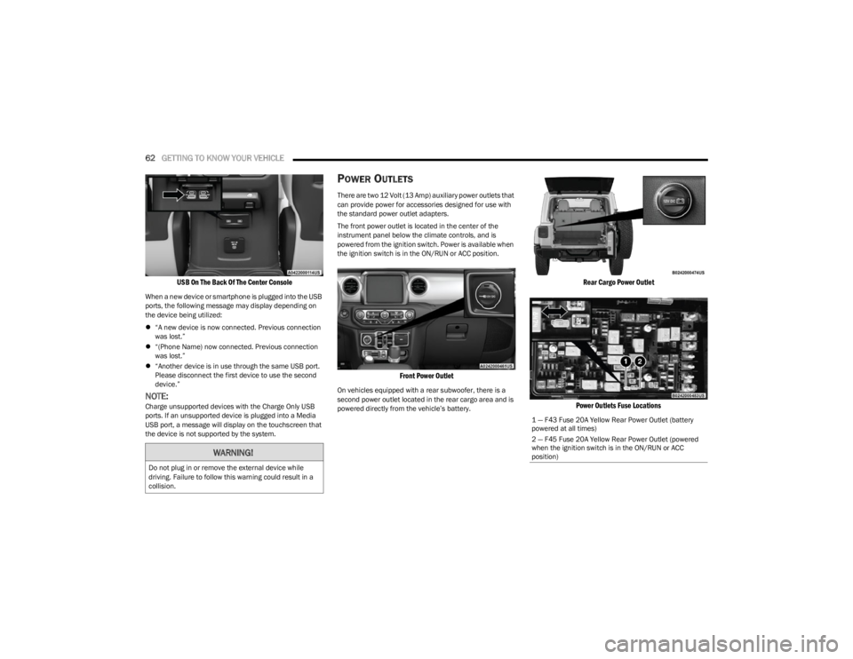
USB On The Back Of The Center Console
When a new device or smartphone is plugged into the USB
ports, the following message may display depending on
the device being utilized:
“A new device is now connected. Previous connection
was lost.”
“(Phone Name) now connected. Previous connection
was lost.”
“Another device is in use through the same USB port.
Please disconnect the first device to use the second
device.”
NOTE:Charge unsupported devices with the Charge Only USB
ports. If an unsupported device is plugged into a Media
USB port, a message will display on the touchscreen that
the device is not supported by the system.
POWER OUTLETS
There are two 12 Volt (13 Amp) auxiliary power outlets that
can provide power for accessories designed for use with
the standard power outlet adapters.
The front power outlet is located in the center of the
instrument panel below the climate controls, and is
powered from the ignition switch. Power is available when
the ignition switch is in the ON/RUN or ACC position.
Front Power Outlet
On vehicles equipped with a rear subwoofer, there is a
second power outlet located in the rear cargo area and is
powered directly from the vehicle’s battery.
Rear Cargo Power Outlet
Power Outlets Fuse Locations
WARNING!
Do not plug in or remove the external device while
driving. Failure to follow this warning could result in a
collision.
1 — F43 Fuse 20A Yellow Rear Power Outlet (battery
powered at all times)
2 — F45 Fuse 20A Yellow Rear Power Outlet (powered
when the ignition switch is in the ON/RUN or ACC
position)
23_JL_OM_EN_USC_t.book Page 62
Page 65 of 396
GETTING TO KNOW YOUR VEHICLE63
(Continued)
POWER INVERTER — IF EQUIPPED
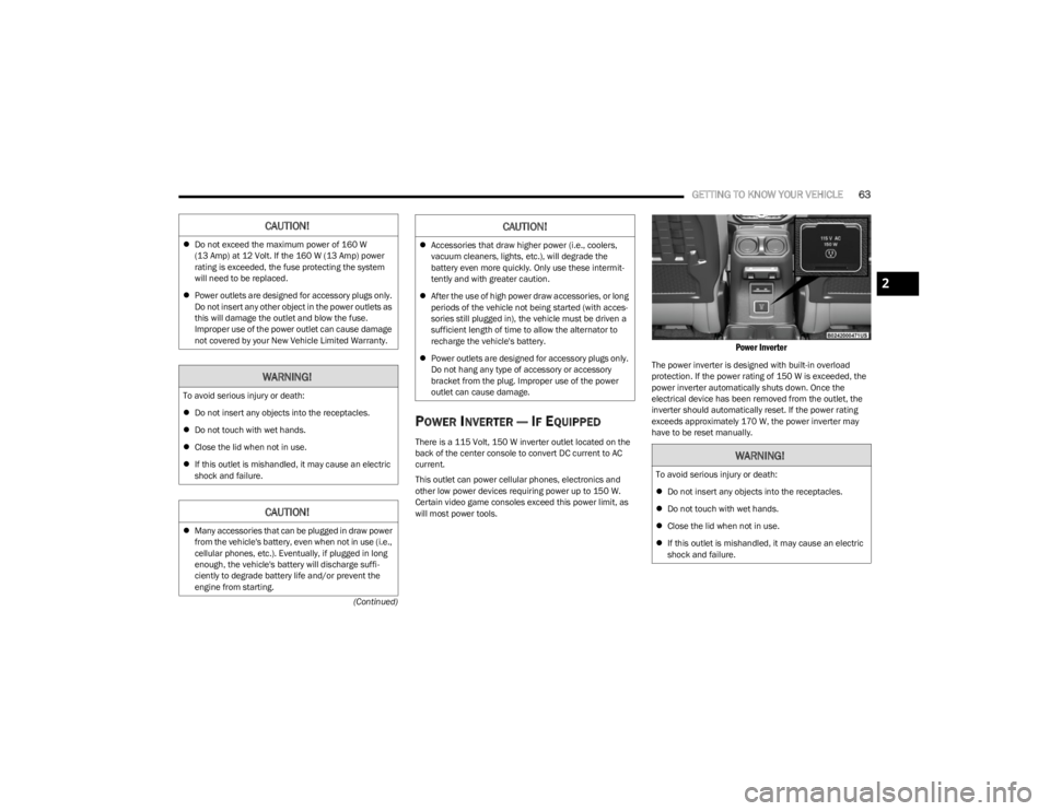
There is a 115 Volt, 150 W inverter outlet located on the
back of the center console to convert DC current to AC
current.
This outlet can power cellular phones, electronics and
other low power devices requiring power up to 150 W.
Certain video game consoles exceed this power limit, as
will most power tools.
Power Inverter
The power inverter is designed with built-in overload
protection. If the power rating of 150 W is exceeded, the
power inverter automatically shuts down. Once the
electrical device has been removed from the outlet, the
inverter should automatically reset. If the power rating
exceeds approximately 170 W, the power inverter may
have to be reset manually.
CAUTION!
Do not exceed the maximum power of 160 W
(13 Amp) at 12 Volt. If the 160 W (13 Amp) power
rating is exceeded, the fuse protecting the system
will need to be replaced.
Power outlets are designed for accessory plugs only.
Do not insert any other object in the power outlets as
this will damage the outlet and blow the fuse.
Improper use of the power outlet can cause damage
not covered by your New Vehicle Limited Warranty.
WARNING!
To avoid serious injury or death:
Do not insert any objects into the receptacles.
Do not touch with wet hands.
Close the lid when not in use.
If this outlet is mishandled, it may cause an electric
shock and failure.
CAUTION!
Many accessories that can be plugged in draw power
from the vehicle's battery, even when not in use (i.e.,
cellular phones, etc.). Eventually, if plugged in long
enough, the vehicle's battery will discharge suffi -
ciently to degrade battery life and/or prevent the
engine from starting.
Accessories that draw higher power (i.e., coolers,
vacuum cleaners, lights, etc.), will degrade the
battery even more quickly. Only use these intermit -
tently and with greater caution.
After the use of high power draw accessories, or long
periods of the vehicle not being started (with acces -
sories still plugged in), the vehicle must be driven a
sufficient length of time to allow the alternator to
recharge the vehicle's battery.
Power outlets are designed for accessory plugs only.
Do not hang any type of accessory or accessory
bracket from the plug. Improper use of the power
outlet can cause damage.
CAUTION!
WARNING!
To avoid serious injury or death:
Do not insert any objects into the receptacles.
Do not touch with wet hands.
Close the lid when not in use.
If this outlet is mishandled, it may cause an electric
shock and failure.
2
23_JL_OM_EN_USC_t.book Page 63
Page 66 of 396
64GETTING TO KNOW YOUR VEHICLE
AUXILIARY SWITCHES — IF EQUIPPED
Four auxiliary switches located in the lower switch bank of
the instrument panel can be used to power various
electrical devices. You have the ability to configure the
functionality of the auxiliary switches via the Uconnect
Settings
Úpage 184.
All switches can be configured as follows:
Switch type operation: Latching or Momentary
Power source: Battery or Ignition
Ability to hold last state across key cycles: On or Off
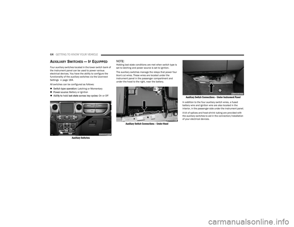
Auxiliary Switches
NOTE:Holding last state conditions are met when switch type is
set to latching and power source is set to ignition.
The auxiliary switches manage the relays that power four
blunt cut wires. These wires are located under the
instrument panel in the passenger compartment and
under the hood to the right, near the battery.
Auxiliary Switch Connections – Under Hood Auxiliary Switch Connections – Under Instrument Panel
In addition to the four auxiliary switch wires, a fused
battery wire and ignition wire are also located in the
interior, in the passenger side under the instrument panel.
A kit of splices and heat shrink tubing are provided with
the auxiliary switches to aid in the connection/installation
of your electrical devices.
23_JL_OM_EN_USC_t.book Page 64
Page 67 of 396
GETTING TO KNOW YOUR VEHICLE65
Wire Color Chart
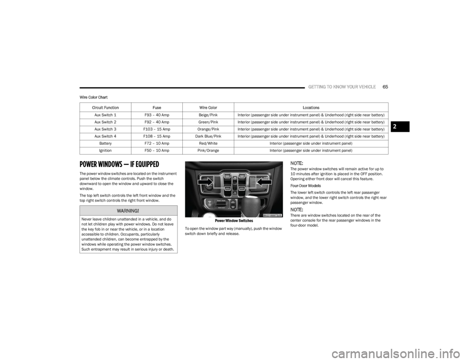
POWER WINDOWS — IF EQUIPPED
The power window switches are located on the instrument
panel below the climate controls. Push the switch
downward to open the window and upward to close the
window.
The top left switch controls the left front window and the
top right switch controls the right front window.
Power Window Switches
To open the window part way (manually), push the window
switch down briefly and release.
NOTE:The power window switches will remain active for up to
10 minutes after ignition is placed in the OFF position.
Opening either front door will cancel this feature.
Four-Door Models
The lower left switch controls the left rear passenger
window, and the lower right switch controls the right rear
passenger window.
NOTE:There are window switches located on the rear of the
center console for the rear passenger windows in the
four-door model.
Circuit Function
FuseWire Color Locations
Aux Switch 1 F93 – 40 Amp Beige/Pink Interior (passenger side under instrument panel) & Underhood (right side near battery)
Aux Switch 2 F92 – 40 Amp Green/Pink Interior (passenger side under instrument panel) & Underhood (right side near battery)
Aux Switch 3 F103 – 15 Amp Orange/Pink Interior (passenger side under instrument panel) & Underhood (right side near battery)
Aux Switch 4 F108 – 15 Amp Dark Blue/Pink Interior (passenger side under instrument panel) & Underhood (right side near battery)
Battery F72 – 10 Amp Red/White Interior (passenger side under instrument panel)
Ignition F50 – 10 Amp Pink/Orange Interior (passenger side under instrument panel)WARNING!
Never leave children unattended in a vehicle, and do
not let children play with power windows. Do not leave
the key fob in or near the vehicle, or in a location
accessible to children. Occupants, particularly
unattended children, can become entrapped by the
windows while operating the power window switches.
Such entrapment may result in serious injury or death.
2
23_JL_OM_EN_USC_t.book Page 65
Page 316 of 396
314SERVICING AND MAINTENANCE
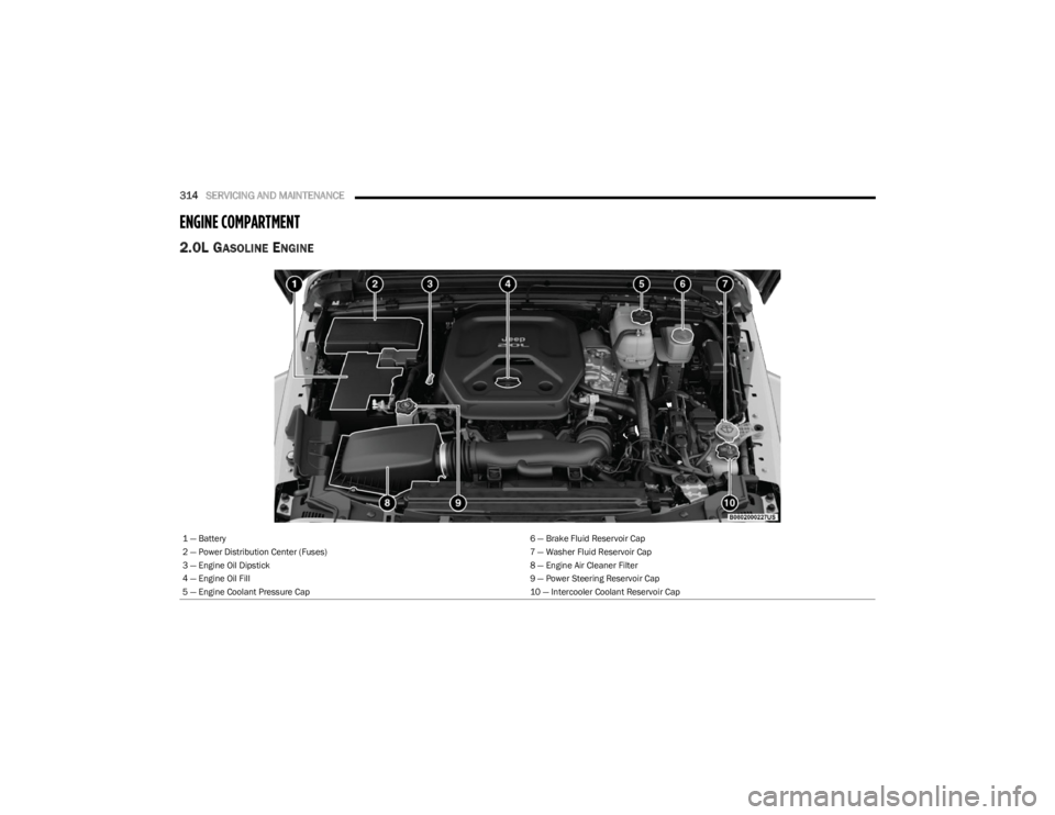
ENGINE COMPARTMENT
2.0L GASOLINE ENGINE
1 — Battery 6 — Brake Fluid Reservoir Cap
2 — Power Distribution Center (Fuses) 7 — Washer Fluid Reservoir Cap
3 — Engine Oil Dipstick 8 — Engine Air Cleaner Filter
4 — Engine Oil Fill 9 — Power Steering Reservoir Cap
5 — Engine Coolant Pressure Cap 10 — Intercooler Coolant Reservoir Cap
23_JL_OM_EN_USC_t.book Page 314
Page 317 of 396
SERVICING AND MAINTENANCE315
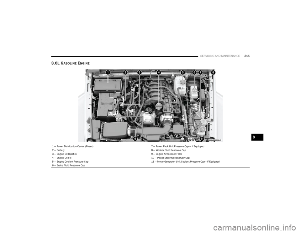
3.6L GASOLINE ENGINE
1 — Power Distribution Center (Fuses) 7 — Power Pack Unit Pressure Cap — If Equipped
2 — Battery 8 — Washer Fluid Reservoir Cap
3 — Engine Oil Dipstick 9 — Engine Air Cleaner Filter
4 — Engine Oil Fill 10 — Power Steering Reservoir Cap
5 — Engine Coolant Pressure Cap 11 — Motor Generator Unit Coolant Pressure Cap— If Equipped
6 — Brake Fluid Reservoir Cap
8
23_JL_OM_EN_USC_t.book Page 315
Page 318 of 396
316SERVICING AND MAINTENANCE
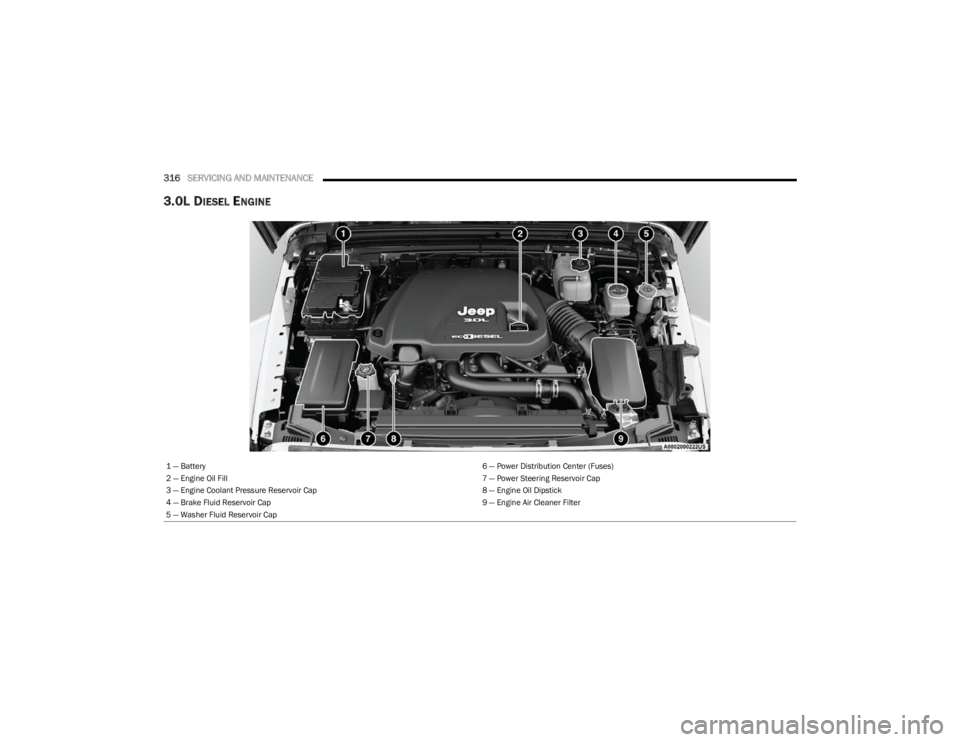
3.0L DIESEL ENGINE
1 — Battery 6 — Power Distribution Center (Fuses)
2 — Engine Oil Fill 7 — Power Steering Reservoir Cap
3 — Engine Coolant Pressure Reservoir Cap 8 — Engine Oil Dipstick
4 — Brake Fluid Reservoir Cap 9 — Engine Air Cleaner Filter
5 — Washer Fluid Reservoir Cap
23_JL_OM_EN_USC_t.book Page 316
Page 335 of 396
SERVICING AND MAINTENANCE333
(Continued)
AUTOMATIC TRANSMISSION —
I
F EQUIPPED
Special Additives
It is strongly recommended against using any special
additives in the transmission. Automatic Transmission
Fluid (ATF) is an engineered product and its performance
may be impaired by supplemental additives. Therefore, do
not add any fluid additives to the transmission. Avoid
using transmission sealers as they may adversely affect
seals.
Fluid Level Check
The fluid level is preset at the factory and does not require
adjustment under normal operating conditions. Routine
fluid level checks are not required; therefore the
transmission has no dipstick. An authorized dealer can
check your transmission fluid level using special service
tools. If you notice fluid leakage or transmission
malfunction, visit an authorized dealer immediately to
have the transmission fluid level checked. Operating the
vehicle with an improper fluid level can cause severe
transmission damage.
Fluid And Filter Changes
Under normal operating conditions, the fluid installed at
the factory will provide satisfactory lubrication for the life
of the vehicle.
Routine fluid and filter changes are not required. However,
change the fluid and filter if the fluid becomes
contaminated (with water, etc.), or if the transmission is
disassembled for any reason.
Selection Of Lubricant
It is important to use the proper transmission fluid to
ensure optimum transmission performance and life. Use
only the manufacturer specified transmission fluid
Úpage 376. It is important to maintain the transmission
fluid at the correct level using the recommended fluid.
NOTE:No chemical flushes should be used in any transmission;
only the approved lubricant should be used.
FUSES
General Information
CAUTION!
Do not use chemical flushes in your transmission as the
chemicals can damage your transmission components.
Such damage is not covered by the New Vehicle Limited
Warranty.
CAUTION!
If a transmission fluid leak occurs, visit an authorized
dealer immediately. Severe transmission damage may
occur. An authorized dealer has the proper tools to
adjust the fluid level accurately.
CAUTION!
Using a transmission fluid other than the manufacturer
recommended fluid may cause deterioration in
transmission shift quality and/or torque converter
shudder
Úpage 376.
WARNING!
When replacing a blown fuse, always use an appro -
priate replacement fuse with the same amp rating as
the original fuse. Never replace a fuse with another
fuse of higher amp rating. The use of a fuse with a
rating other than indicated may result in a dangerous
electrical system overload. If a properly rated fuse
continues to blow, it indicates a problem in the circuit
that must be corrected. Never replace a blown fuse
with metal wires or any other material. Failure to use
proper fuses may result in serious personal injury,
fire and/or property damage.
Before replacing a fuse, make sure that the ignition
is off and that all the other services are switched off
and/or disengaged.
If the replaced fuse blows again, contact an autho -
rized dealer.
8
23_JL_OM_EN_USC_t.book Page 333
Page 336 of 396
334SERVICING AND MAINTENANCE
The fuses protect electrical systems against excessive
current.
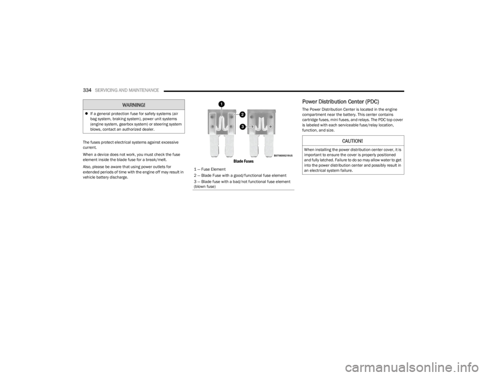
When a device does not work, you must check the fuse
element inside the blade fuse for a break/melt.
Also, please be aware that using power outlets for
extended periods of time with the engine off may result in
vehicle battery discharge.
Blade Fuses
Power Distribution Center (PDC)
The Power Distribution Center is located in the engine
compartment near the battery. This center contains
cartridge fuses, mini fuses, and relays. The PDC top cover
is labeled with each serviceable fuse/relay location,
function, and size.
If a general protection fuse for safety systems (air
bag system, braking system), power unit systems
(engine system, gearbox system) or steering system
blows, contact an authorized dealer.WARNING!
1 — Fuse Element
2 — Blade Fuse with a good/functional fuse element
3 — Blade fuse with a bad/not functional fuse element
(blown fuse)
CAUTION!
When installing the power distribution center cover, it is
important to ensure the cover is properly positioned
and fully latched. Failure to do so may allow water to get
into the power distribution center and possibly result in
an electrical system failure.
23_JL_OM_EN_USC_t.book Page 334