tow JEEP WRANGLER 2023 Owners Manual
[x] Cancel search | Manufacturer: JEEP, Model Year: 2023, Model line: WRANGLER, Model: JEEP WRANGLER 2023Pages: 396, PDF Size: 25.15 MB
Page 2 of 396

WARNING: Operating, servicing and maintaining a passenger vehicle or off-highway
motor vehicle can expose you to chemicals including engine exhaust, carbon monoxide,
phthalates, and lead, which are known to the State of California to cause cancer and
birth defects or other reproductive harm. To minimize exposure, avoid breathing exhaust,
do not idle the engine except as necessary, service your vehicle in a well-ventilated area
and wear gloves or wash your hands frequently when servicing your vehicle. For more
information go to www.P65Warnings.ca.gov/passenger-vehicle.
The driver’s primary responsibility is the safe operation of the vehicle. Driving while distracted can result in loss of vehicle control, resulting in an accident and personal injury. FCA US LLC strongly recommends that the driver use extreme caution when using any device or feature that may take their attention off the road. Use of any electrical devices, such as cellular telephones, computers, portable radios, vehicle navigation or other devices by the driver while the vehicle is moving is dangerous and could lead to a serious accident. Texting while driving is also dangerous and should never be done while the vehicle is moving. If you find yourself unable to devote your full attention to vehicle operation, pull off the road to a safe location and stop your vehicle. Some states or provinces prohibit the use of cellular telephones or texting while driving. It is always the driver’s responsibility to comply with all local laws.
This Owner’s Manual has been prepared to help you get acquainted with your new Jeep® brand vehicle and to provide a convenient reference source for common questions.
Not all features shown in this manual may apply to your vehicle. For additional information, visit mopar.com/om (USA), owners.mopar.ca (Canada) or your local Jeep® brand dealer.
U.S. Residents: If you are the first registered retail owner of your vehicle, you may obtain a complimentary printed copy of the Warranty Booklet by calling 1-877-426-5337 or by contacting your dealer. Replacement kits can be purchased by visiting www.techauthority.com.
Canadian Residents: If you are the first registered retail owner of your vehicle, you may obtain a complimentary printed copy of the Warranty Booklet or purchase a replacement kit by calling 1-800-387-1143 or by contacting your dealer.
DRIVING AND ALCOHOL
Drunk driving is one of the most frequent causes of accidents. Your driving ability can be seriously impaired with blood alcohol levels far below the legal minimum. If you are drinking, don’t drive. Ride with a designated non-drinking driver, call a cab, a rideshare, a friend or use public transportation.
WARNING
Driving after drinking can lead to an accident. Your perceptions are less sharp, your reflexes are slower and your judgment is impaired when you have been drinking. Never drink and then drive.
This Owner’s Manual illustrates and describes the operation of features and equipment that are either standard or optional on this vehicle. This manual may also include a description of features and equipment that are no longer available or were not ordered on this vehicle. Please disregard any features and equipment described in this manual that are not on this vehicle. FCA US LLC reserves the right to make changes in design and specifications, and/or make additions to or improvements to its products without imposing any obligation upon itself to install them on products previously manufactured.
With respect to any vehicles sold in Canada, the name FCA US LLC shall be deemed to be deleted and the name FCA Canada Inc. used in substitution therefore.
This Owner’s Manual is intended to familiarize you with the important features of your vehicle. Your most up-to-date Owner’s Manual, Navigation/Uconnect manuals and Warranty Booklet can be found by visiting the website on the back cover.
ROADSIDE ASSISTANCE 24 HOURS, 7 DAYS A WEEK AT YOUR SERVICE. CALL 1-800-521-2779 OR VISIT CHRYSLER.RSAHELP.COM (USA) CALL 1-800-363-4869 OR VISIT FCA.ROADSIDEAID.COM (CANADA) SERVICES: Flat Tire Service, Out Of Gas/Fuel Delivery, Battery Jump Assistance, Lockout Service and Towing Service
Please see the Customer Assistance chapter in this Owner’s Manual for further information.
FCA US LLC reserves the right to modify the terms or discontinue the Roadside Assistance Program at any time. The Roadside Assistance Program is subject to restrictions and conditions of use, that are determined solely by FCA US LLC.
Page 6 of 396
4
NORMAL OPERATION — DIESEL ENGINE ..................... 130
Cold Weather Precautions........................................ 131Engine Idling .............................................................. 131Stopping The Engine ................................................. 132
Cooling System Tips — Automatic Transmission..... 132
ENGINE BREAK-IN RECOMMENDATIONS —
GASOLINE ENGINE (IF EQUIPPED) ................................ 133
ENGINE BREAK-IN RECOMMENDATIONS — DIESEL
ENGINE (IF EQUIPPED) .................................................... 133
PARKING BRAKE ............................................................. 133
MANUAL TRANSMISSION — IF EQUIPPED .................... 134 Shifting....................................................................... 135
Downshifting.............................................................. 136
AUTOMATIC TRANSMISSION — IF EQUIPPED .............. 137 Ignition Park Interlock............................................... 137Brake/Transmission Shift Interlock (BTSI)
System ...................................................................... 138
8–Speed Automatic Transmission .......................... 138
FOUR–WHEEL DRIVE OPERATION ............................... 140 Four-Position Transfer Case — If Equipped ............ 141Five-Position Transfer Case — If Equipped .............. 142
Trac-Lok Rear Axle — If Equipped ............................ 144
Axle Lock (Tru-Lok) Front And Rear — If Equipped ... 144
Axle Lock (Tru-Lok) Rear Only — If Equipped .......... 144
Electronic Sway Bar Disconnect — If Equipped ...... 145
Off Road+ — If Equipped........................................... 146
ELECTRO-HYDRAULIC POWER STEERING .................... 146
STOP/START SYSTEM — AUTOMATIC TRANSMISSION
(IF EQUIPPED) .................................................................. 147 Autostop Mode .......................................................... 147
Possible Reasons The Engine Does Not Autostop.. 148
To Start The Engine While In Autostop Mode.......... 148
To Manually Turn Off The Stop/Start System ......... 148
To Manually Turn On The Stop/Start System.......... 149
System Malfunction .................................................. 149 STOP/START SYSTEM — MANUAL TRANSMISSION
(IF EQUIPPED) .................................................................. 149
Autostop Mode.......................................................... 149
Possible Reasons The Engine Does Not
Autostop .................................................................... 150
To Start The Engine While In Autostop Mode ......... 150
To Manually Turn Off The Stop/Start System ......... 150
To Manually Turn On The Stop/Start System ......... 151
System Malfunction.................................................. 151
CRUISE CONTROL SYSTEMS — IF EQUIPPED ............. 151 Cruise Control ........................................................... 151
Adaptive Cruise Control (ACC).................................. 152
PARKSENSE REAR PARK ASSIST — IF EQUIPPED ...... 160 ParkSense Sensors .................................................. 160ParkSense Warning Display ..................................... 160
ParkSense Display.................................................... 160
Enabling And Disabling ParkSense ......................... 162
Service The ParkSense Rear Park Assist System... 162
Cleaning The ParkSense System ............................. 163ParkSense System Usage Precautions ................... 163
PARKVIEW REAR BACK UP CAMERA ........................... 163
TRAILCAM SYSTEM — IF EQUIPPED .............................. 164
REFUELING THE VEHICLE — GASOLINE ENGINE
(IF EQUIPPED) .................................................................. 165 Fuel Filler Cap ........................................................... 165
Loose Fuel Filler Cap Message ............................... 166
REFUELING THE VEHICLE — DIESEL ENGINE
(IF EQUIPPED) .................................................................. 166 Avoid Using Contaminated Fuel............................... 167
Bulk Fuel Storage — Diesel Fuel .............................. 167
Diesel Exhaust Fluid ................................................. 167
VEHICLE LOADING ........................................................... 169 Certification Label..................................................... 169 TRAILER TOWING ............................................................170
Common Towing Definitions..................................... 170
Trailer Hitch Classification ........................................ 172Trailer Towing Weights (Maximum Trailer Weight
Ratings) ..................................................................... 172
Trailer And Tongue Weight........................................ 173Towing Requirements ............................................... 173Towing Tips ................................................................ 175
RECREATIONAL TOWING (BEHIND MOTORHOME) ...... 176 Towing This Vehicle Behind Another Vehicle ........... 176Recreational Towing — Four-Wheel Drive Models ... 176
DRIVING TIPS ....................................................................178 On-Road Driving Tips ................................................. 178
Off-Road Driving Tips................................................. 178
MULTIMEDIA
UCONNECT SYSTEMS ......................................................184
CYBERSECURITY ..............................................................184
UCONNECT SETTINGS ......................................................184 Customer Programmable Features ......................... 184
UCONNECT INTRODUCTION ............................................ 197 System Overview ...................................................... 197Drag & Drop Menu Bar ............................................. 200Safety And General Information ............................... 200
UCONNECT MODES .......................................................... 201 Steering Wheel Audio Controls ................................ 201Radio Mode .............................................................. 201
Media Mode .............................................................. 210
Phone Mode ............................................................. 212
23_JL_OM_EN_USC_t.book Page 4
Page 7 of 396
5
ANDROID AUTO™ & APPLE CARPLAY® —
IF EQUIPPED ..................................................................... 222Android Auto™
S
.................................................... 222
Apple CarPlay®
S
.................................................. 224
Android Auto™ And Apple CarPlay® Tips And
Tricks.......................................................................... 225
CONNECTED VEHICLE SERVICES — IF EQUIPPED ...... 225 Is My Vehicle Connected? ........................................ 225Introduction To Connected Vehicle Services .......... 226
Getting Started With Connected Vehicle Services ... 227
Using SiriusXM Guardian™ ...................................... 228
Manage My SiriusXM Guardian™ Account ............. 237
CONNECTED SERVICES FAQS ....................................... 237 Connected Services SOS FAQs — If Equipped ........ 237
Connected Services Remote Door Lock/Unlock
FAQs .......................................................................... 237
Connected Services Roadside Assistance FAQs .... 237Connected Services Send & Go FAQs —
If Equipped ............................................................... 238
Connected Services Vehicle Finder FAQs ............... 238
Connected Services Stolen Vehicle Assistance
FAQs — If Equipped .................................................. 238
Connected Services Remote Vehicle Start FAQs ... 238
Connected Services Remote Horn & Lights FAQs .. 239
Connected Services Account FAQs — If Equipped .. 239
Data Collection & Privacy ......................................... 240
RADIO OPERATION AND MOBILE PHONES .................. 240 Regulatory And Safety Information .......................... 241
OFF-ROAD PAGES — IF EQUIPPED ................................ 241 Off-Road Pages Status Bar ...................................... 241
Drivetrain .................................................................. 242
Accessory Gauge ...................................................... 242Pitch & Roll ............................................................... 242
TrailCam — If Equipped ............................................. 243
SAFETY
SAFETY FEATURES .......................................................... 244 Anti-Lock Brake System (ABS) ................................ 244
Rear Seat Reminder Alert (RSRA) — If Equipped .... 244
Electronic Brake Control (EBC) System .................. 245
AUXILIARY DRIVING SYSTEMS ...................................... 252 Blind Spot Monitoring (BSM) — If Equipped ........... 252
Forward Collision Warning (FCW) With
Mitigation — If Equipped........................................... 255Tire Pressure Monitoring System (TPMS) ............... 257
OCCUPANT RESTRAINT SYSTEMS ............................... 261 Occupant Restraint Systems Features ................... 261
Important Safety Precautions .................................. 261
Seat Belt Systems .................................................... 261
Supplemental Restraint Systems (SRS).................. 267
Child Restraints ........................................................ 277
SAFETY TIPS ..................................................................... 288 Transporting Passengers ......................................... 288
Transporting Pets ..................................................... 288
Connected Vehicles .................................................. 288Safety Checks You Should Make Inside The
Vehicle ...................................................................... 288
Periodic Safety Checks You Should Make Outside
The Vehicle ................................................................ 290Exhaust Gas .............................................................. 290
Carbon Monoxide Warnings ..................................... 290
IN CASE OF EMERGENCY
HAZARD WARNING FLASHERS ..................................... 291
ASSIST AND SOS SYSTEM — IF EQUIPPED .................. 291 JACKING AND TIRE CHANGING
S
...............................293
Preparations For Jacking ......................................... 294
Jack Location ............................................................ 294 Spare Tire Removal .................................................. 295
Jacking Instructions .................................................. 295
JUMP STARTING ..............................................................298 Preparations For Jump Start..................................... 298
Jump Starting Procedure .......................................... 299
IF YOUR ENGINE OVERHEATS......................................... 300
MANUAL PARK RELEASE ................................................301
FREEING A STUCK VEHICLE ........................................... 302
TOWING A DISABLED VEHICLE.......................................303 Four–Wheel Drive Models ........................................ 303Without The Key Fob ................................................. 304
Emergency Tow Hooks — If Equipped ..................... 304
ENHANCED ACCIDENT RESPONSE SYSTEM (EARS) ..305
EVENT DATA RECORDER (EDR)......................................305
SERVICING AND MAINTENANCE
SCHEDULED SERVICING — GASOLINE ENGINE ...........306 Maintenance Plan ..................................................... 307
SCHEDULED SERVICING — DIESEL ENGINE .................310 Maintenance Plan — Diesel Fuel Up To B5
Biodiesel .................................................................... 311Additional Maintenance — B6 To B20 Biodiesel ..... 313
ENGINE COMPARTMENT ................................................. 314 2.0L Gasoline Engine ............................................... 3143.6L Gasoline Engine ............................................... 3153.0L Diesel Engine .................................................... 316
Checking Oil Level ..................................................... 317Adding Washer Fluid ................................................. 317
Maintenance-Free Battery ....................................... 317Pressure Washing ..................................................... 318
23_JL_OM_EN_USC_t.book Page 5
Page 27 of 396
GETTING TO KNOW YOUR VEHICLE25
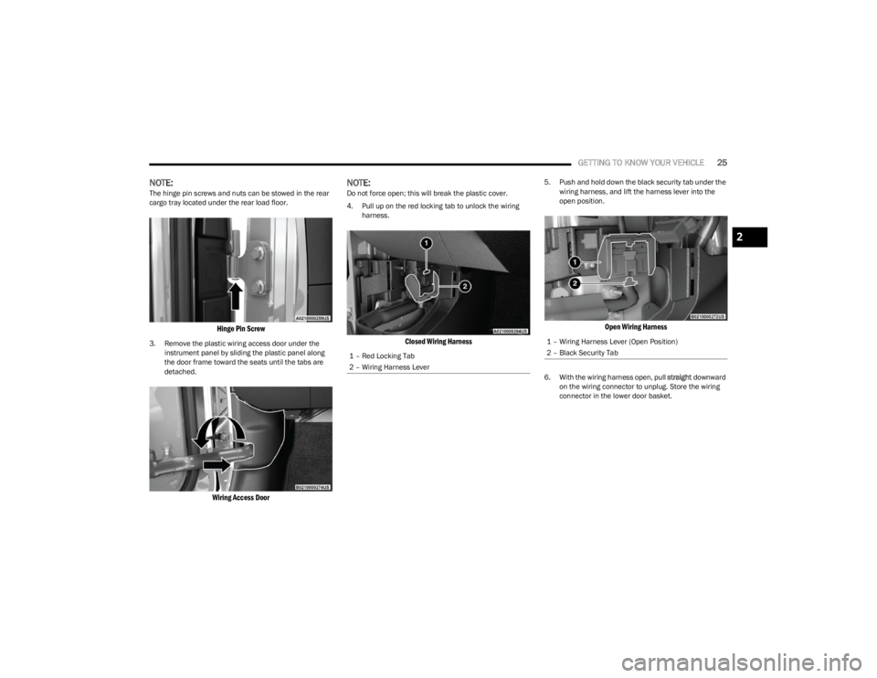
NOTE:The hinge pin screws and nuts can be stowed in the rear
cargo tray located under the rear load floor.
Hinge Pin Screw
3. Remove the plastic wiring access door under the
instrument panel by sliding the plastic panel along
the door frame toward the seats until the tabs are
detached.
Wiring Access Door
NOTE:Do not force open; this will break the plastic cover.
4. Pull up on the red locking tab to unlock the wiring harness.
Closed Wiring Harness
5. Push and hold down the black security tab under the wiring harness, and lift the harness lever into the
open position.
Open Wiring Harness
6. With the wiring harness open, pull straight downward
on the wiring connector to unplug. Store the wiring
connector in the lower door basket.
1 – Red Locking Tab
2 – Wiring Harness Lever
1 – Wiring Harness Lever (Open Position)
2 – Black Security Tab
2
23_JL_OM_EN_USC_t.book Page 25
Page 30 of 396
28GETTING TO KNOW YOUR VEHICLE
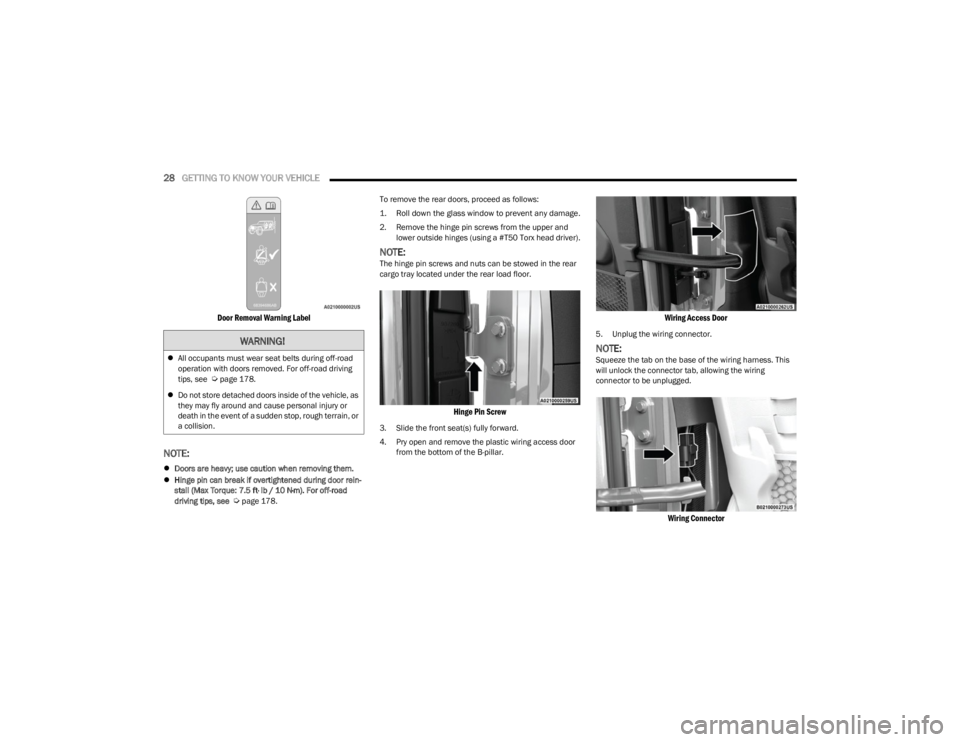
Door Removal Warning Label
NOTE:
Doors are heavy; use caution when removing them.
Hinge pin can break if overtightened during door rein -
stall (Max Torque: 7.5 ft· lb / 10 N·m). For off-road
driving tips, see
Úpage 178. To remove the rear doors, proceed as follows:
1. Roll down the glass window to prevent any damage.
2. Remove the hinge pin screws from the upper and
lower outside hinges (using a #T50 Torx head driver).
NOTE:The hinge pin screws and nuts can be stowed in the rear
cargo tray located under the rear load floor.
Hinge Pin Screw
3. Slide the front seat(s) fully forward.
4. Pry open and remove the plastic wiring access door from the bottom of the B-pillar.
Wiring Access Door
5. Unplug the wiring connector.
NOTE:Squeeze the tab on the base of the wiring harness. This
will unlock the connector tab, allowing the wiring
connector to be unplugged.
Wiring Connector
WARNING!
All occupants must wear seat belts during off-road
operation with doors removed. For off-road driving
tips, see
Úpage 178.
Do not store detached doors inside of the vehicle, as
they may fly around and cause personal injury or
death in the event of a sudden stop, rough terrain, or
a collision.
23_JL_OM_EN_USC_t.book Page 28
Page 32 of 396
30GETTING TO KNOW YOUR VEHICLE
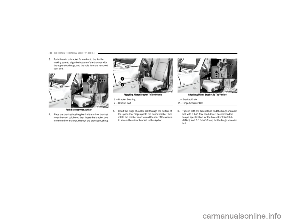
3. Push the mirror bracket forward onto the A-pillar,
making sure to align the bottom of the bracket with
the upper door hinge, and the hole from the removed
cowl bolt.
Push Bracket Onto A-pillar
4. Place the bracket bushing behind the mirror bracket (over the cowl bolt hole), then insert the bracket bolt
into the mirror bracket, through the bracket bushing.
Attaching Mirror Bracket To The Vehicle
5. Insert the hinge shoulder bolt through the bottom of the upper door hinge up into the mirror bracket, then
rotate the bracket knob toward the rear of the vehicle
to secure the mirror bracket to the A-pillar.
Attaching Mirror Bracket To The Vehicle
6. Tighten both the bracket bolt and the hinge shoulder bolt with a #40 Torx head driver. Recommended
torque specification for the bracket bolt is 6 ft-lb
(8 N·m), and 7.5 ft-lb (10 N·m) for the hinge shoulder bolt.
1 — Bracket Bushing
2 — Bracket Bolt1 — Bracket Knob
2 — Hinge Shoulder Bolt
23_JL_OM_EN_USC_t.book Page 30
Page 36 of 396
34GETTING TO KNOW YOUR VEHICLE
Lower Door Adjustment
If the door does not latch properly after installation, if
there is interference between the panels, or if a
non-uniform gap around the door is observed when the
door is closed (example: door position appears to be low
and too far rearward), the position of the door on its hinges
may need to be adjusted. To do this, proceed as follows:
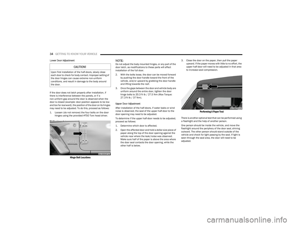
1. Loosen (do not remove) the four bolts on the door
hinges using the provided #T50 Torx head driver.
Hinge Bolt Locations
NOTE:Do not adjust the body mounted hinges, or any part of the
door latch, as modifications to these parts will affect
installation of the full door.
2. With the bolts loose, the door can be moved forward by pushing the door handle toward the front of the
vehicle, and/or upward by grabbing the door handle
and lifting towards the roof.
3. Once the gaps between the door and vehicle body are uniform around the entire door, tighten the door
hinge bolts to 20.3 ft· lb / 27.5 N·m (Max Torque:
27.3 ft· lb / 37 N·m).
Upper Door Adjustment
After installation of the half-doors, if water leaks or wind
noise is observed, the seal of the upper half-door to the
door opening may need to be adjusted.
To determine if the upper half-door needs to be adjusted,
proceed as follows:
1. Determine which door is affected.
2. Open the affected door and hold a dollar-size piece of paper along the top of the door opening against the
vehicle near where the leak/noise was observed.
Make sure half of the paper is above the area where
the door seal contacts the door opening, while the
other half is below. 3. Close the door on the paper, then pull the paper
upward. If the paper moves with little to no effort, the
upper half-door will need to be adjusted in that area
to increase seal compression.
Performing A Paper Test
There is another optional test that can be performed using
a flashlight and the help of another person.
One person should be inside the vehicle, and move the
flashlight around the periphery of the door seal, shining
outward. The other person should stand outside of the
vehicle and check for light passing by the seal. If light is
seen through the seal area, the door will need to be
adjusted.
CAUTION!
Upon first installation of the half-doors, slowly close
each door to check for body contact. Improper setting of
the door hinges can cause extreme non-uniform
conditions, and result in damage to the body around
the door.
23_JL_OM_EN_USC_t.book Page 34
Page 38 of 396
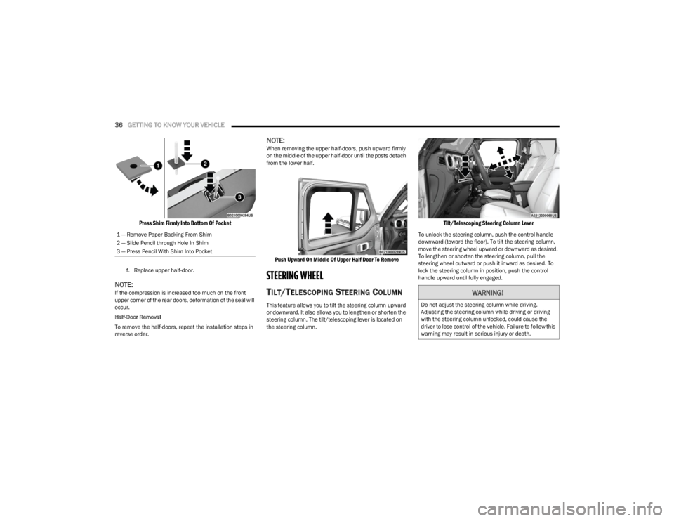
36GETTING TO KNOW YOUR VEHICLE
Press Shim Firmly Into Bottom Of Pocket
f. Replace upper half-door.
NOTE:If the compression is increased too much on the front
upper corner of the rear doors, deformation of the seal will
occur.
Half-Door Removal
To remove the half-doors, repeat the installation steps in
reverse order.
NOTE:When removing the upper half-doors, push upward firmly
on the middle of the upper half-door until the posts detach
from the lower half.
Push Upward On Middle Of Upper Half Door To Remove
STEERING WHEEL
TILT/TELESCOPING STEERING COLUMN
This feature allows you to tilt the steering column upward
or downward. It also allows you to lengthen or shorten the
steering column. The tilt/telescoping lever is located on
the steering column.
Tilt/Telescoping Steering Column Lever
To unlock the steering column, push the control handle
downward (toward the floor). To tilt the steering column,
move the steering wheel upward or downward as desired.
To lengthen or shorten the steering column, pull the
steering wheel outward or push it inward as desired. To
lock the steering column in position, push the control
handle upward until fully engaged.
1 — Remove Paper Backing From Shim
2 — Slide Pencil through Hole In Shim
3 — Press Pencil With Shim Into Pocket
WARNING!
Do not adjust the steering column while driving.
Adjusting the steering column while driving or driving
with the steering column unlocked, could cause the
driver to lose control of the vehicle. Failure to follow this
warning may result in serious injury or death.
23_JL_OM_EN_USC_t.book Page 36
Page 44 of 396
42GETTING TO KNOW YOUR VEHICLE
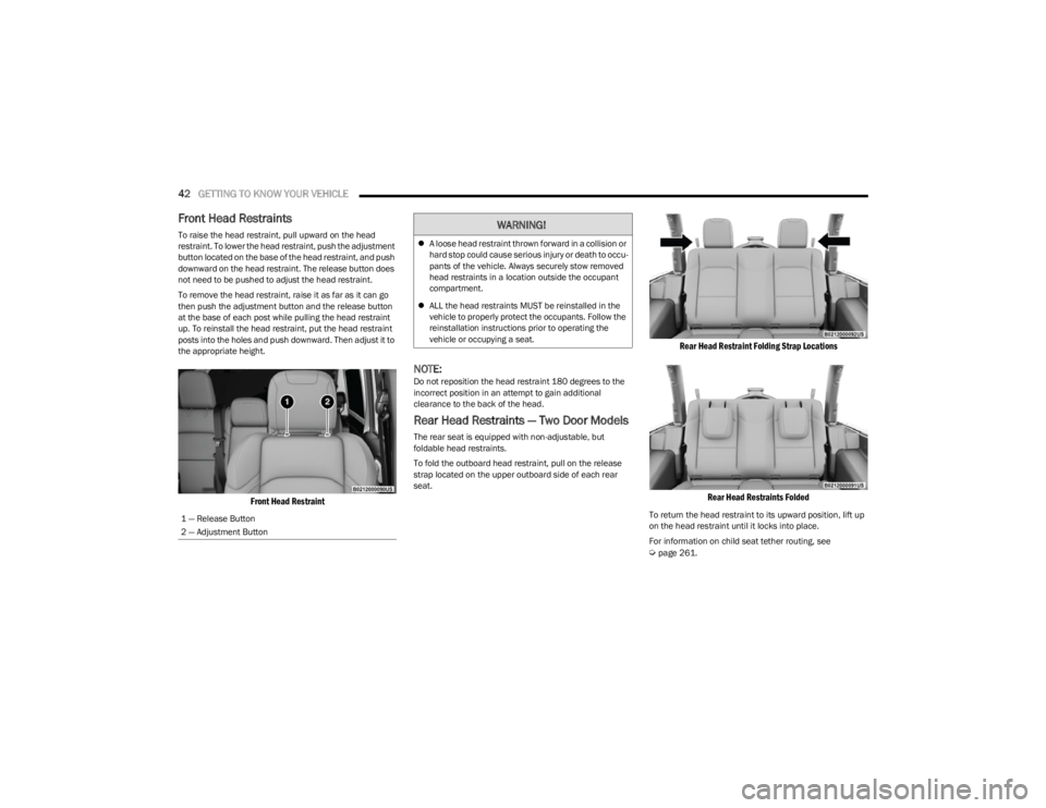
Front Head Restraints
To raise the head restraint, pull upward on the head
restraint. To lower the head restraint, push the adjustment
button located on the base of the head restraint, and push
downward on the head restraint. The release button does
not need to be pushed to adjust the head restraint.
To remove the head restraint, raise it as far as it can go
then push the adjustment button and the release button
at the base of each post while pulling the head restraint
up. To reinstall the head restraint, put the head restraint
posts into the holes and push downward. Then adjust it to
the appropriate height.
Front Head Restraint
NOTE:Do not reposition the head restraint 180 degrees to the
incorrect position in an attempt to gain additional
clearance to the back of the head.
Rear Head Restraints — Two Door Models
The rear seat is equipped with non-adjustable, but
foldable head restraints.
To fold the outboard head restraint, pull on the release
strap located on the upper outboard side of each rear
seat.
Rear Head Restraint Folding Strap Locations
Rear Head Restraints Folded
To return the head restraint to its upward position, lift up
on the head restraint until it locks into place.
For information on child seat tether routing, see
Úpage 261.
1 — Release Button
2 — Adjustment Button
WARNING!
A loose head restraint thrown forward in a collision or
hard stop could cause serious injury or death to occu -
pants of the vehicle. Always securely stow removed
head restraints in a location outside the occupant
compartment.
ALL the head restraints MUST be reinstalled in the
vehicle to properly protect the occupants. Follow the
reinstallation instructions prior to operating the
vehicle or occupying a seat.
23_JL_OM_EN_USC_t.book Page 42
Page 45 of 396
GETTING TO KNOW YOUR VEHICLE43
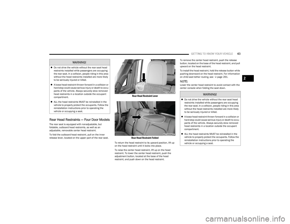
Rear Head Restraints — Four Door Models
The rear seat is equipped with nonadjustable, but
foldable, outboard head restraints, as well as an
adjustable, removable center head restraint.
To fold the outboard head restraint, pull on the inner
release lever, located on the upper part of the rear seat.
Rear Head Restraint Lever
Rear Head Restraint Folded
To return the head restraint to its upward position, lift up
on the head restraint until it locks into place.
To raise the center head restraint, lift up on the head
restraint. To lower the center head restraint, push the
adjustment button, located at the base of the head
restraint, and push down on the head restraint. To remove the center head restraint, push the release
button, located on the base of the head restraint, and pull
upward on the head restraint.
To install the head restraint, hold the release button while
pushing downward on the head restraint. For information
on child seat tether routing, see
Úpage 261.
NOTE:Lower the center head restraint to avoid contact with the
center console when folding the seat down.
WARNING!
Do not drive the vehicle without the rear seat head
restraints installed while passengers are occupying
the rear seat. In a collision, people riding in this area
without the head restraints installed are more likely
to be seriously injured or killed.
A loose head restraint thrown forward in a collision or
hard stop could cause serious injury or death to occu -
pants of the vehicle. Always securely stow removed
head restraints in a location outside the occupant
compartment.
ALL the head restraints MUST be reinstalled in the
vehicle to properly protect the occupants. Follow the
reinstallation instructions prior to operating the
vehicle or occupying a seat.
2
23_JL_OM_EN_USC_t.book Page 43