tow JEEP WRANGLER 2023 User Guide
[x] Cancel search | Manufacturer: JEEP, Model Year: 2023, Model line: WRANGLER, Model: JEEP WRANGLER 2023Pages: 396, PDF Size: 25.15 MB
Page 47 of 396
GETTING TO KNOW YOUR VEHICLE45
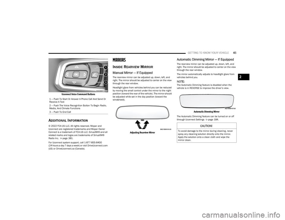
Uconnect Voice Command Buttons
ADDITIONAL INFORMATION
© 2022 FCA US LLC. All rights reserved. Mopar and
Uconnect are registered trademarks and Mopar Owner
Connect is a trademark of FCA US LLC. SiriusXM® and all
related marks and logos are trademarks of SiriusXM®
Radio Inc.
Úpage 381.
For Uconnect system support, call 1-877-855-8400
(24 hours a day 7 days a week) or visit DriveUconnect.com
(US) or DriveUconnect.ca (Canada).
MIRRORS
INSIDE REARVIEW MIRROR
Manual Mirror — If Equipped
The rearview mirror can be adjusted up, down, left, and
right. The mirror should be adjusted to center on the view
through the rear window.
Headlight glare from vehicles behind you can be reduced
by moving the small control under the mirror to the night
position (toward the rear of the vehicle). The mirror should
be adjusted while set in the day position (toward the
windshield).
Adjusting Rearview Mirror
Automatic Dimming Mirror — If Equipped
The rearview mirror can be adjusted up, down, left, and
right. The mirror should be adjusted to center on the view
through the rear window.
The mirror automatically adjusts to headlight glare from
vehicles behind you.
NOTE:The Automatic Dimming feature is disabled when the
vehicle is in REVERSE to improve the driver’s view.
Automatic Dimming Mirror
The Automatic Dimming feature can be turned on or off
through Uconnect Settings Úpage 184.
1 — Push To Start Or Answer A Phone Call And Send Or
Receive A Text
2 — Push The Voice Recognition Button To Begin Radio,
Media, And Climate Functions
3 — Push To End Call
CAUTION!
To avoid damage to the mirror during cleaning, never
spray any cleaning solution directly onto the mirror.
Apply the solution onto a clean cloth and wipe the
mirror clean.
2
23_JL_OM_EN_USC_t.book Page 45
Page 53 of 396
GETTING TO KNOW YOUR VEHICLE51
NOTE:For vehicles sold in Canada, rotate the headlight switch
clockwise from the parking lights and instrument panel
lights position to the first detent to turn on headlights,
parking lights, and instrument panel lights. Rotate the
headlight switch to the second detent for the AUTO
position.
DAYTIME RUNNING LIGHTS (DRLS) —
I
F EQUIPPED
The Daytime Running Lights are active when the low
beams are not on, and the engine is running. DRLs may be
deactivated by applying the parking brake.
NOTE:
For vehicles sold in Canada, the Daytime Running
Lights will automatically deactivate when the front fog
lights are turned on.
On some vehicles, the Daytime Running Lights may
deactivate, or reduce intensity, on one side of the
vehicle (when a turn signal is activated on that side), or
on both sides of the vehicle (when the hazard warning
lights are activated).
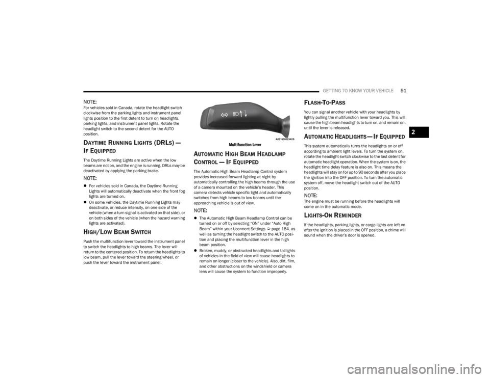
HIGH/LOW BEAM SWITCH
Push the multifunction lever toward the instrument panel
to switch the headlights to high beams. The lever will
return to the centered position. To return the headlights to
low beam, pull the lever toward the steering wheel, or
push the lever toward the instrument panel.
Multifunction Lever
AUTOMATIC HIGH BEAM HEADLAMP
C
ONTROL — IF EQUIPPED
The Automatic High Beam Headlamp Control system
provides increased forward lighting at night by
automatically controlling the high beams through the use
of a camera mounted on the vehicle’s header. This
camera detects vehicle specific light and automatically
switches from high beams to low beams until the
approaching vehicle is out of view.
NOTE:
The Automatic High Beam Headlamp Control can be
turned on or off by selecting “ON” under “Auto High
Beam” within your Uconnect Settings
Úpage 184, as
well as turning the headlight switch to the AUTO posi -
tion and placing the multifunction lever in the high
beam position.
Broken, muddy, or obstructed headlights and taillights
of vehicles in the field of view will cause headlights to
remain on longer (closer to the vehicle). Also, dirt, film,
and other obstructions on the windshield or camera
lens will cause the system to function improperly.
FLASH-TO-PASS
You can signal another vehicle with your headlights by
lightly pulling the multifunction lever toward you. This will
cause the high beam headlights to turn on, and remain on,
until the lever is released.
AUTOMATIC HEADLIGHTS — IF EQUIPPED
This system automatically turns the headlights on or off
according to ambient light levels. To turn the system on,
rotate the headlight switch clockwise to the last detent for
automatic headlight operation. When the system is on, the
headlight time delay feature is also on. This means the
headlights will stay on for up to 90 seconds after you place
the ignition into the OFF position. To turn the automatic
system off, move the headlight switch out of the AUTO
position.
NOTE:The engine must be running before the headlights will
come on in the automatic mode.
LIGHTS-ON REMINDER
If the headlights, parking lights, or cargo lights are left on
after the ignition is placed in the OFF position, a chime will
sound when the driver’s door is opened.
2
23_JL_OM_EN_USC_t.book Page 51
Page 55 of 396
GETTING TO KNOW YOUR VEHICLE53
DIMMER CONTROL
The dimmer control is part of the headlight switch and is
located on the left side of the instrument panel.
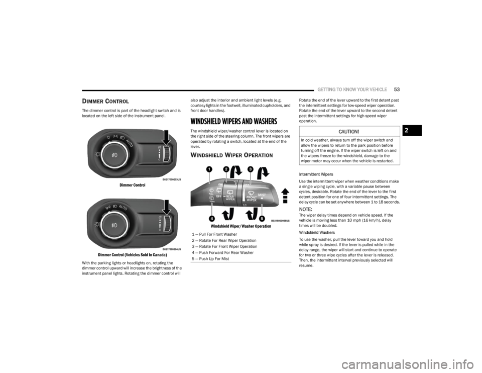
Dimmer Control
Dimmer Control (Vehicles Sold In Canada)
With the parking lights or headlights on, rotating the
dimmer control upward will increase the brightness of the
instrument panel lights. Rotating the dimmer control will also adjust the interior and ambient light levels (e.g.
courtesy lights in the footwell, illuminated cupholders, and
front door handles).
WINDSHIELD WIPERS AND WASHERS
The windshield wiper/washer control lever is located on
the right side of the steering column. The front wipers are
operated by rotating a switch, located at the end of the
lever.
WINDSHIELD WIPER OPERATION
Windshield Wiper/Washer Operation
Rotate the end of the lever upward to the first detent past
the intermittent settings for low-speed wiper operation.
Rotate the end of the lever upward to the second detent
past the intermittent settings for high-speed wiper
operation.
Intermittent Wipers
Use the intermittent wiper when weather conditions make
a single wiping cycle, with a variable pause between
cycles, desirable. Rotate the end of the lever to the first
detent position for one of four intermittent settings. The
delay cycle can be set anywhere between 1 to 18 seconds.
NOTE:The wiper delay times depend on vehicle speed. If the
vehicle is moving less than 10 mph (16 km/h), delay
times will be doubled.
Windshield Washers
To use the washer, pull the lever toward you and hold
while spray is desired. If the lever is pulled while in the
delay range, the wiper will start and continue to operate
for two or three wipe cycles after the lever is released.
Then, the intermittent interval previously selected will
resume.
1 — Pull For Front Washer
2 — Rotate For Rear Wiper Operation
3 — Rotate For Front Wiper Operation
4 — Push Forward For Rear Washer
5 — Push Up For Mist
CAUTION!
In cold weather, always turn off the wiper switch and
allow the wipers to return to the park position before
turning off the engine. If the wiper switch is left on and
the wipers freeze to the windshield, damage to the
wiper motor may occur when the vehicle is restarted.
2
23_JL_OM_EN_USC_t.book Page 53
Page 56 of 396
54GETTING TO KNOW YOUR VEHICLE
If the lever is pulled while in the off position, the wipers will
operate for two or three wipe cycles. Then, the wipers will
turn off.
NOTE:As a protective measure, the washer will stop if the switch
is held for more than 20 seconds. Once the switch is
released the washer will resume normal operation.
Mist
Push upward on the wiper lever to activate a single wipe to
clear off-road mist or spray from a passing vehicle. As long
as the lever is held up, the wipers will continue to operate.
NOTE:The mist feature does not activate the washer pump;
therefore, no washer fluid will be sprayed on the wind -
shield. The washer function must be used in order to spray
the windshield with washer fluid.
For information on wiper care and replacement, see
Úpage 326.
REAR WINDOW WIPER/WASHER —
I
F EQUIPPED
A rotary switch on the center portion of the windshield
wiper/washer lever controls the operation of the rear
wiper/washer function.
Rotate the switch upward to the first detent
position for intermittent operation and to the
second detent for continuous rear wiper
operation.
Push the wiper lever toward the instrument
panel to activate the rear washer. The washer
pump and wiper will continue to operate as
long as the lever is held.
NOTE:As a protective measure, the washer will stop if the switch
is held for more than 20 seconds. Once the switch is
released the washer will resume normal operation.
If the rear wiper is operating when the ignition is placed in
the OFF position, the wiper will automatically return to the
parked position. When the vehicle is restarted, the wiper
will resume function at whichever position the switch is set
at.
CLIMATE CONTROLS
The Climate Control system allows you to regulate the
temperature, air flow, and direction of air circulating
throughout the vehicle. The controls are located on the
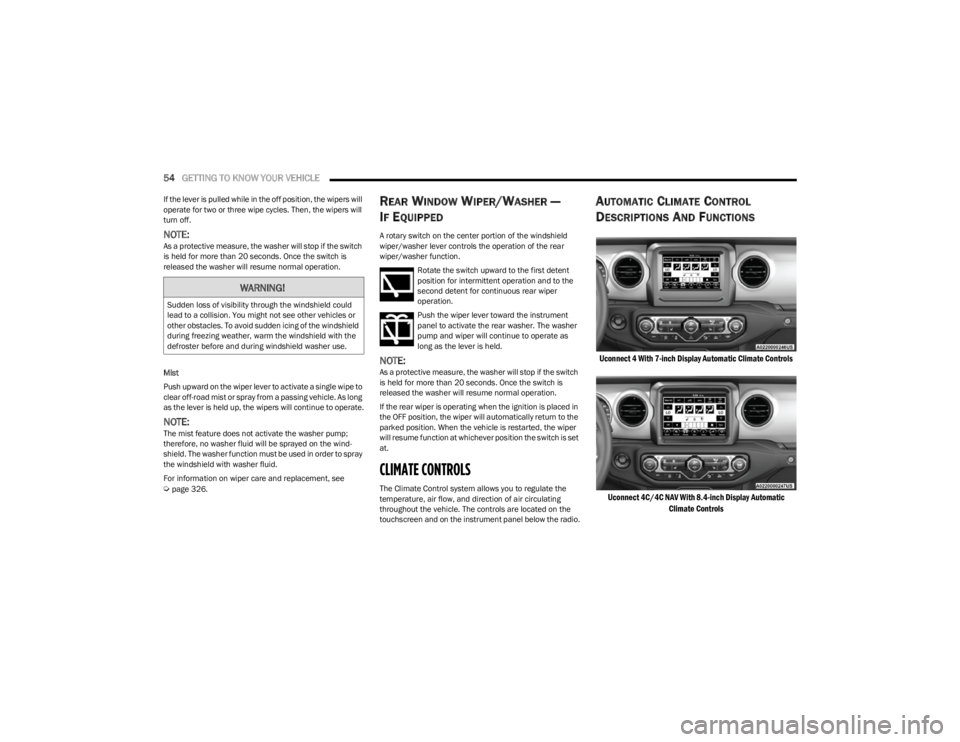
touchscreen and on the instrument panel below the radio.
AUTOMATIC CLIMATE CONTROL
D
ESCRIPTIONS AND FUNCTIONS
Uconnect 4 With 7-inch Display Automatic Climate Controls
Uconnect 4C/4C NAV With 8.4-inch Display Automatic Climate Controls
WARNING!
Sudden loss of visibility through the windshield could
lead to a collision. You might not see other vehicles or
other obstacles. To avoid sudden icing of the windshield
during freezing weather, warm the windshield with the
defroster before and during windshield washer use.
23_JL_OM_EN_USC_t.book Page 54
Page 58 of 396
56GETTING TO KNOW YOUR VEHICLE
Driver And Passenger Temperature Up And
Down Buttons
Provides the driver and passenger with independent
temperature control.
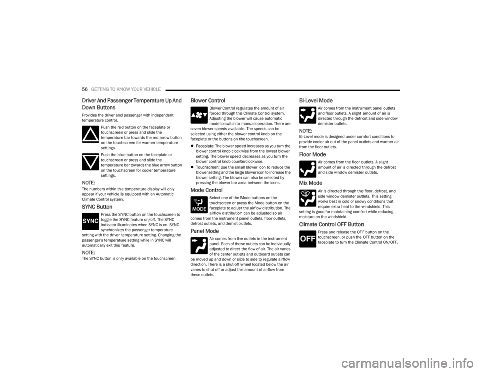
Push the red button on the faceplate or
touchscreen or press and slide the
temperature bar towards the red arrow button
on the touchscreen for warmer temperature
settings.
Push the blue button on the faceplate or
touchscreen or press and slide the
temperature bar towards the blue arrow button
on the touchscreen for cooler temperature
settings.
NOTE:The numbers within the temperature display will only
appear if your vehicle is equipped with an Automatic
Climate Control system.
SYNC Button
Press the SYNC button on the touchscreen to
toggle the SYNC feature on/off. The SYNC
indicator illuminates when SYNC is on. SYNC
synchronizes the passenger temperature
setting with the driver temperature setting. Changing the
passenger’s temperature setting while in SYNC will
automatically exit this feature.
NOTE:The SYNC button is only available on the touchscreen.
Blower Control
Blower Control regulates the amount of air
forced through the Climate Control system.
Adjusting the blower will cause automatic
mode to switch to manual operation. There are
seven blower speeds available. The speeds can be
selected using either the blower control knob on the
faceplate or the buttons on the touchscreen.
Faceplate: The blower speed increases as you turn the
blower control knob clockwise from the lowest blower
setting. The blower speed decreases as you turn the
blower control knob counterclockwise.
Touchscreen: Use the small blower icon to reduce the
blower setting and the large blower icon to increase the
blower setting. The blower can also be selected by
pressing the blower bar area between the icons.
Mode Control
Select one of the Mode buttons on the
touchscreen or press the Mode button on the
faceplate to adjust the airflow distribution. The
airflow distribution can be adjusted so air
comes from the instrument panel outlets, floor outlets,
defrost outlets, and demist outlets.
Panel Mode
Air comes from the outlets in the instrument
panel. Each of these outlets can be individually
adjusted to direct the flow of air. The air vanes
of the center outlets and outboard outlets can
be moved up and down or side to side to regulate airflow
direction. There is a shut-off wheel located below the air
vanes to shut off or adjust the amount of airflow from
these outlets.
Bi-Level Mode
Air comes from the instrument panel outlets
and floor outlets. A slight amount of air is
directed through the defrost and side window
demister outlets.
NOTE:Bi-Level mode is designed under comfort conditions to
provide cooler air out of the panel outlets and warmer air
from the floor outlets.
Floor Mode
Air comes from the floor outlets. A slight
amount of air is directed through the defrost
and side window demister outlets.
Mix Mode
Air is directed through the floor, defrost, and
side window demister outlets. This setting
works best in cold or snowy conditions that
require extra heat to the windshield. This
setting is good for maintaining comfort while reducing
moisture on the windshield.
Climate Control OFF Button
Press and release the OFF button on the
touchscreen, or push the OFF button on the
faceplate to turn the Climate Control ON/OFF.
23_JL_OM_EN_USC_t.book Page 56
Page 75 of 396

GETTING TO KNOW YOUR VEHICLE73
5. While keeping the rear window level, slide to the left
until it is completely separate from its retainer. Do not
pull downward while removing the rear window.
Damage to the retainer could result.
Step Five
Remove The Right And Left Quarter Windows:
1. Through the rear opening, push the bottom corner outward and release tab from the bottom of the
window pillar.
Step One
2. Undo the hook-and-loop fastener located at the upper front corner of each quarter window.
Step Two
3. Starting at the rear of the vehicle, remove plastic retainer from along the bottom of the window moving
toward the front of the vehicle.
Step Three
4. Remove plastic retainer from the bottom to the top of the front window.
Step Four
2
23_JL_OM_EN_USC_t.book Page 73
Page 78 of 396
76GETTING TO KNOW YOUR VEHICLE
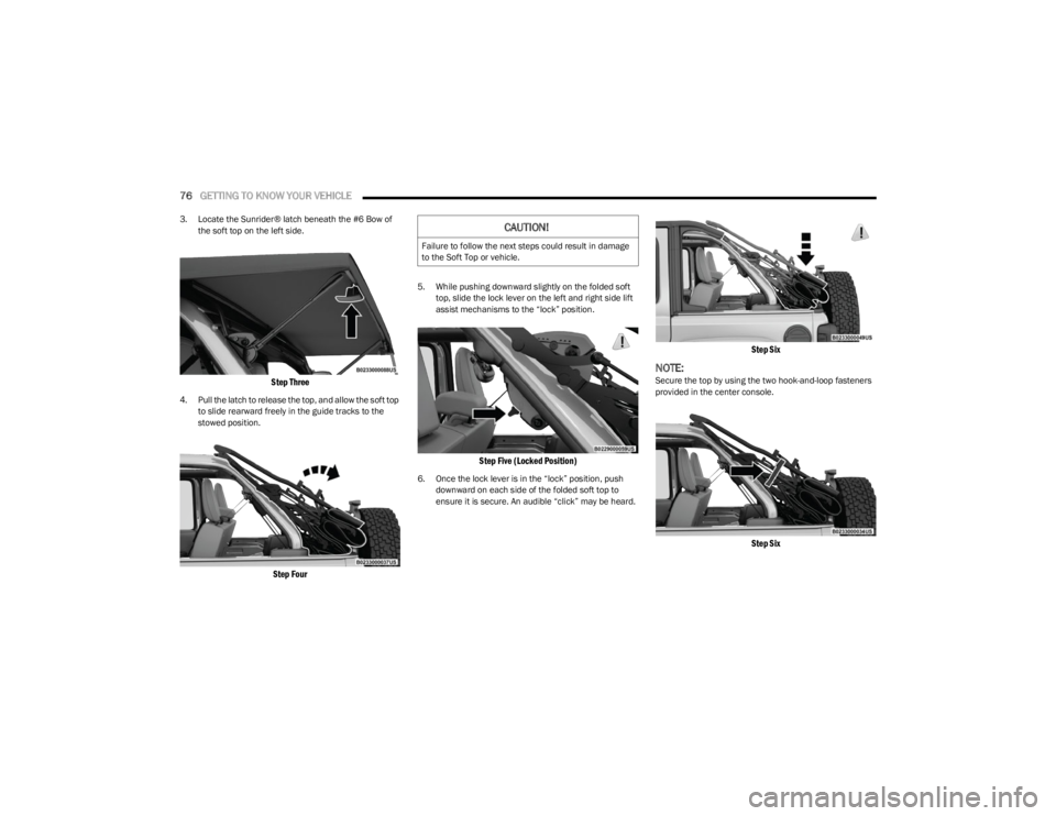
3. Locate the Sunrider® latch beneath the #6 Bow of
the soft top on the left side.
Step Three
4. Pull the latch to release the top, and allow the soft top to slide rearward freely in the guide tracks to the
stowed position.
Step Four
5. While pushing downward slightly on the folded soft top, slide the lock lever on the left and right side lift
assist mechanisms to the “lock” position.
Step Five (Locked Position)
6. Once the lock lever is in the “lock” position, push downward on each side of the folded soft top to
ensure it is secure. An audible “click” may be heard.
Step Six
NOTE:Secure the top by using the two hook-and-loop fasteners
provided in the center console.
Step Six
CAUTION!
Failure to follow the next steps could result in damage
to the Soft Top or vehicle.
23_JL_OM_EN_USC_t.book Page 76
Page 79 of 396
GETTING TO KNOW YOUR VEHICLE77
RAISING THE SOFT TOP
Use this QR code to access your digital
experience.
Raising The Soft Top From The Fully
Lowered Position
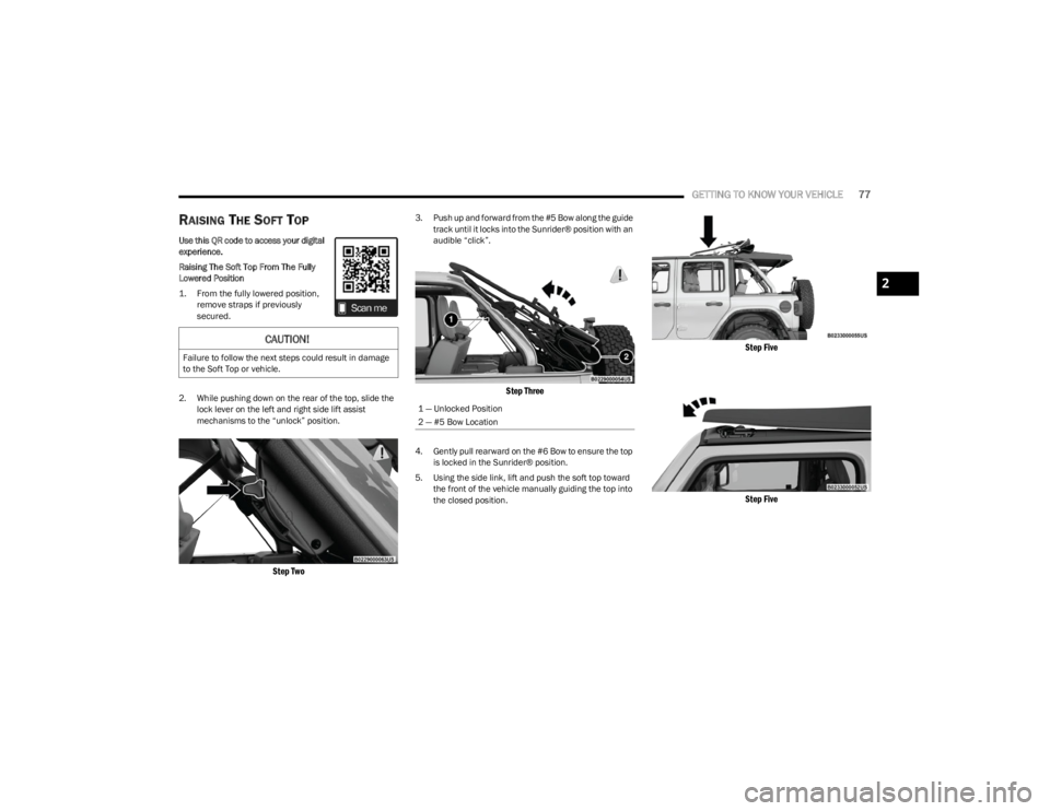
1. From the fully lowered position,
remove straps if previously
secured.
2. While pushing down on the rear of the top, slide the lock lever on the left and right side lift assist
mechanisms to the “unlock” position.
Step Two
3. Push up and forward from the #5 Bow along the guide track until it locks into the Sunrider® position with an
audible “click”.
Step Three
4. Gently pull rearward on the #6 Bow to ensure the top is locked in the Sunrider® position.
5. Using the side link, lift and push the soft top toward the front of the vehicle manually guiding the top into
the closed position.
Step Five
Step Five
CAUTION!
Failure to follow the next steps could result in damage
to the Soft Top or vehicle.
1 — Unlocked Position
2 — #5 Bow Location
2
23_JL_OM_EN_USC_t.book Page 77
Page 84 of 396
82GETTING TO KNOW YOUR VEHICLE
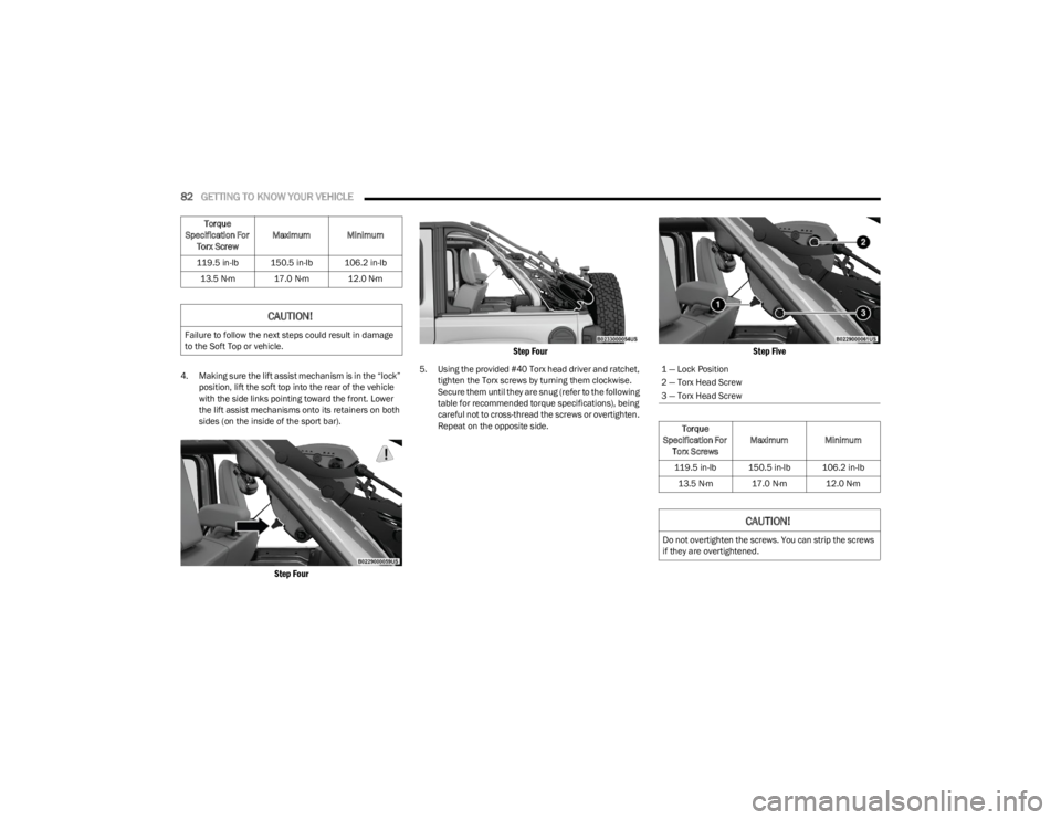
4. Making sure the lift assist mechanism is in the “lock”
position, lift the soft top into the rear of the vehicle
with the side links pointing toward the front. Lower
the lift assist mechanisms onto its retainers on both
sides (on the inside of the sport bar).
Step Four Step Four
5. Using the provided #40 Torx head driver and ratchet,
tighten the Torx screws by turning them clockwise.
Secure them until they are snug (refer to the following
table for recommended torque specifications), being
careful not to cross-thread the screws or overtighten.
Repeat on the opposite side.
Step Five
Torque
Specification For Torx Screw Maximum Minimum
119.5 in-lb 150.5 in-lb 106.2 in-lb 13.5 N·m 17.0 N·m 12.0 N·m
CAUTION!
Failure to follow the next steps could result in damage
to the Soft Top or vehicle.
1 — Lock Position
2 — Torx Head Screw
3 — Torx Head Screw
Torque
Specification For Torx Screws Maximum Minimum
119.5 in-lb 150.5 in-lb 106.2 in-lb 13.5 N·m 17.0 N·m 12.0 N·m
CAUTION!
Do not overtighten the screws. You can strip the screws
if they are overtightened.
23_JL_OM_EN_USC_t.book Page 82
Page 110 of 396
108GETTING TO KNOW YOUR INSTRUMENT PANEL
Use this QR code to access your digital
experience.
INSTRUMENT CLUSTER DESCRIPTIONS
1.
Tachometer
Indicates the engine speed in revolutions per
minute (RPM x 1000).
2. Temperature Gauge
The temperature gauge shows engine coolant
temperature. Any reading within the normal range
indicates that the engine cooling system is oper -
ating satisfactorily.
The pointer will likely indicate a higher tempera -
ture when driving in hot weather, up mountain
grades, or when towing a trailer. It should not be
allowed to exceed the upper limits of the normal
operating range. 3.
Instrument Cluster Display
The instrument cluster display features a driver
interactive display
Úpage 108. 4.
Fuel Gauge
The pointer shows the level of fuel in the fuel tank
when the ignition switch is in the ON/RUN posi -
tion.
The fuel pump symbol points to the side
of the vehicle where the fuel filler door is
located.
5. Speedometer
Indicates vehicle speed.
INSTRUMENT CLUSTER DISPLAY
Your vehicle will be equipped with an instrument cluster
display, which offers useful information to the driver. With
the ignition in the OFF mode, opening/closing of a door will
activate the display for viewing, and display the total miles,
or kilometers, in the odometer. Your instrument cluster
display is designed to display important information about
your vehicle’s systems and features. Using a driver
interactive display located on the instrument panel, your
instrument cluster display can show you how systems are
working and give you warnings when they aren’t. The
steering wheel mounted controls allow you to scroll
through and enter the main menus and submenus. You
can access the specific information you want and make
selections and adjustments.CAUTION!
Do not operate the engine with the tachometer pointer
in the red area. Engine damage will occur.
WARNING!
A hot engine cooling system is dangerous. You or others
could be badly burned by steam or boiling coolant. It is
recommended to call an authorized dealer for service if
your vehicle overheats.
CAUTION!
Driving with a hot engine cooling system could damage
your vehicle. If the temperature gauge reads “H” pull
over and stop the vehicle. Idle the vehicle with the air
conditioner turned off until the pointer drops back into
the normal range. If the pointer remains on the “H”,
turn the engine off immediately and call an authorized
dealer for service.
23_JL_OM_EN_USC_t.book Page 108