length JEEP WRANGLER UNLIMITED 2018 Owner handbook (in English)
[x] Cancel search | Manufacturer: JEEP, Model Year: 2018, Model line: WRANGLER UNLIMITED, Model: JEEP WRANGLER UNLIMITED 2018Pages: 348, PDF Size: 6.5 MB
Page 35 of 348

To raise the center head restraint, lift up on
the head restraint. To lower the center head
restraint, push the adjustment button, lo-
cated at the base of the head restraint, and
push down on the head restraint.
To remove the center head restraint, push the
release button, located on the base of the
head restraint, and pull upward on the head
restraint.
To install the head restraint, hold the release
button while pushing downward on the head
restraint. Refer to “Occupant Restraint Sys-
tems” in “Safety” for information on child
seat tether routing.
NOTE:
Lower the center head restraint to avoid con-
tact with the center console when folding the
seat down.
WARNING!
• Do not drive the vehicle without the rear
seat head restraints installed while pas-
sengers are occupying the rear seat. In a
collision, people riding in this area with-
WARNING!
out the head restraints installed are
more likely to be seriously injured or
killed.
• A loose head restraint thrown forward in
a collision or hard stop could cause se-
rious injury or death to occupants of the
vehicle. Always securely stow removed
head restraints in a location outside the
occupant compartment.
• ALL the head restraints MUST be rein-
stalled in the vehicle to properly protect
the occupants. Follow the reinstallation
instructions above prior to operating the
vehicle or occupying a seat.
STEERING WHEEL
Tilt/Telescoping Steering Column
This feature allows you to tilt the steering
column upward or downward. It also allows
you to lengthen or shorten the steering col-
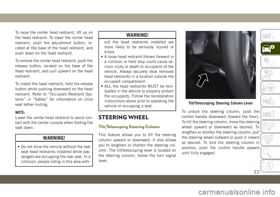
umn. The tilt/telescoping lever is located on
the steering column, below the turn signal
lever.To unlock the steering column, push the
control handle downward (toward the floor).
To tilt the steering column, move the steering
wheel upward or downward as desired. To
lengthen or shorten the steering column, pull
the steering wheel outward or push it inward
as desired. To lock the steering column in
position, push the control handle upward
until fully engaged.
Tilt/Telescoping Steering Column Lever
33
Page 61 of 348

CAUTION!
life and/or prevent the engine from start-
ing.
• Accessories that draw higher power (i.e.,
coolers, vacuum cleaners, lights, etc.),
will degrade the battery even more
quickly. Only use these intermittently
and with greater caution.
• After the use of high power draw acces-
sories, or long periods of the vehicle not
being started (with accessories still
plugged in), the vehicle must be driven a
sufficient length of time to allow the
alternator to recharge the vehicle's bat-
tery.
• Power outlets are designed for accessory
plugs only. Do not hang any type of
accessory or accessory bracket from the
plug. Improper use of the power outlet
can cause damage.
Power Inverter — If Equipped
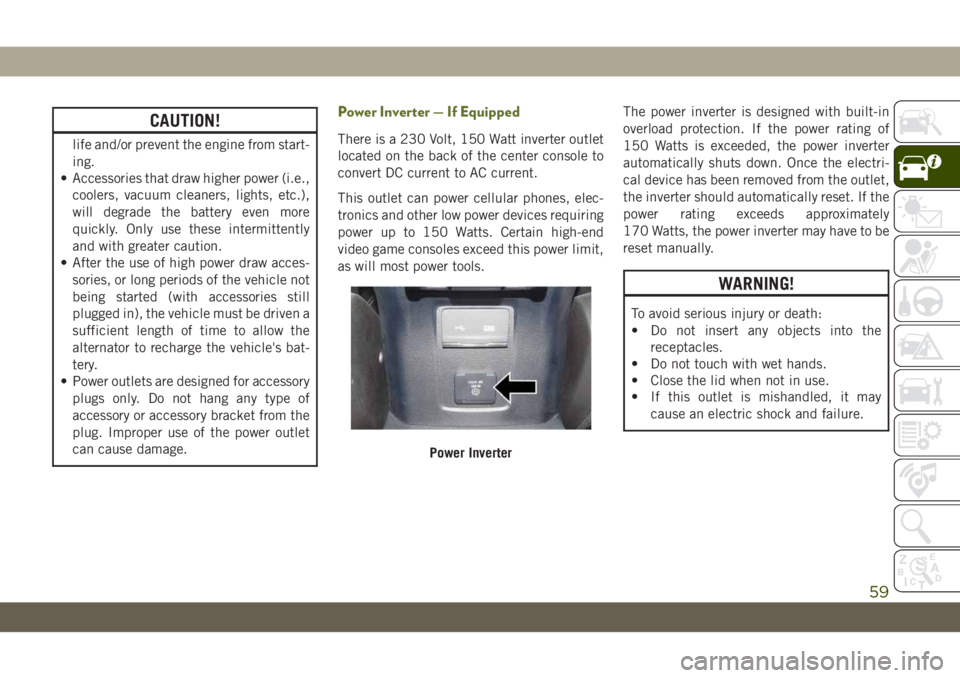
There is a 230 Volt, 150 Watt inverter outlet
located on the back of the center console to
convert DC current to AC current.
This outlet can power cellular phones, elec-
tronics and other low power devices requiring
power up to 150 Watts. Certain high-end
video game consoles exceed this power limit,
as will most power tools.The power inverter is designed with built-in
overload protection. If the power rating of
150 Watts is exceeded, the power inverter
automatically shuts down. Once the electri-
cal device has been removed from the outlet,
the inverter should automatically reset. If the
power rating exceeds approximately
170 Watts, the power inverter may have to be
reset manually.
WARNING!
To avoid serious injury or death:
• Do not insert any objects into the
receptacles.
• Do not touch with wet hands.
• Close the lid when not in use.
• If this outlet is mishandled, it may
cause an electric shock and failure.
Power Inverter
59
Page 93 of 348

Feedback To The Driver
The instrument cluster has an HDC icon and
the HDC switch has an indicator light, which
offers feedback to the driver about the state
HDC is in.
• The cluster icon and switch indicator light
will illuminate and remain on solid when
HDC is enabled or activated. This is the
normal operating condition for HDC.
• The cluster icon and switch indicator light
will flash for several seconds then extin-
guish when the driver pushes the HDC
switch but enable conditions are not met.
• The cluster icon and switch indicator light
will flash for several seconds then extin-
guish when HDC disables due to excess
speed.
• The cluster icon and switch indicator light
will flash when HDC deactivates due to
overheated brakes. The flashing will stop
and HDC will activate again once the brakes
have cooled sufficiently.WARNING!
HDC is only intended to assist the driver in
controlling vehicle speed when descend-
ing hills. The driver must remain attentive
to the driving conditions and is responsible
for maintaining a safe vehicle speed.
AUXILIARY DRIVING
SYSTEMS
Blind Spot Monitoring (BSM) — If
Equipped
The Blind Spot Monitoring (BSM) system
uses two radar-based sensors, located inside
the taillights, to detect highway licensable
vehicles (automobiles, trucks, motorcycles,
etc.) that enter the blind spot zones from the
rear/front/side of the vehicle.When the vehicle is started, the BSM warning
light will momentarily illuminate in both out-
side rear view mirrors to let the driver know
that the system is operational. The BSM
system sensors operate when the vehicle is in
any forward gear or REVERSE and enters
stand-by mode when the vehicle is in PARK.
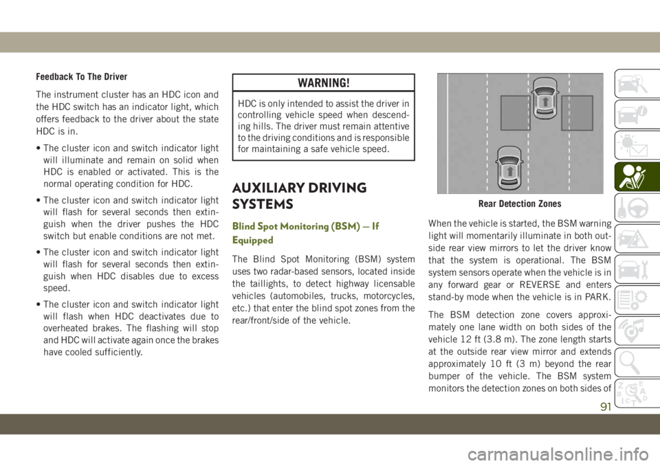
The BSM detection zone covers approxi-
mately one lane width on both sides of the
vehicle 12 ft (3.8 m). The zone length starts
at the outside rear view mirror and extends
approximately 10 ft (3 m) beyond the rear
bumper of the vehicle. The BSM system
monitors the detection zones on both sides of
Rear Detection Zones
91
Page 249 of 348

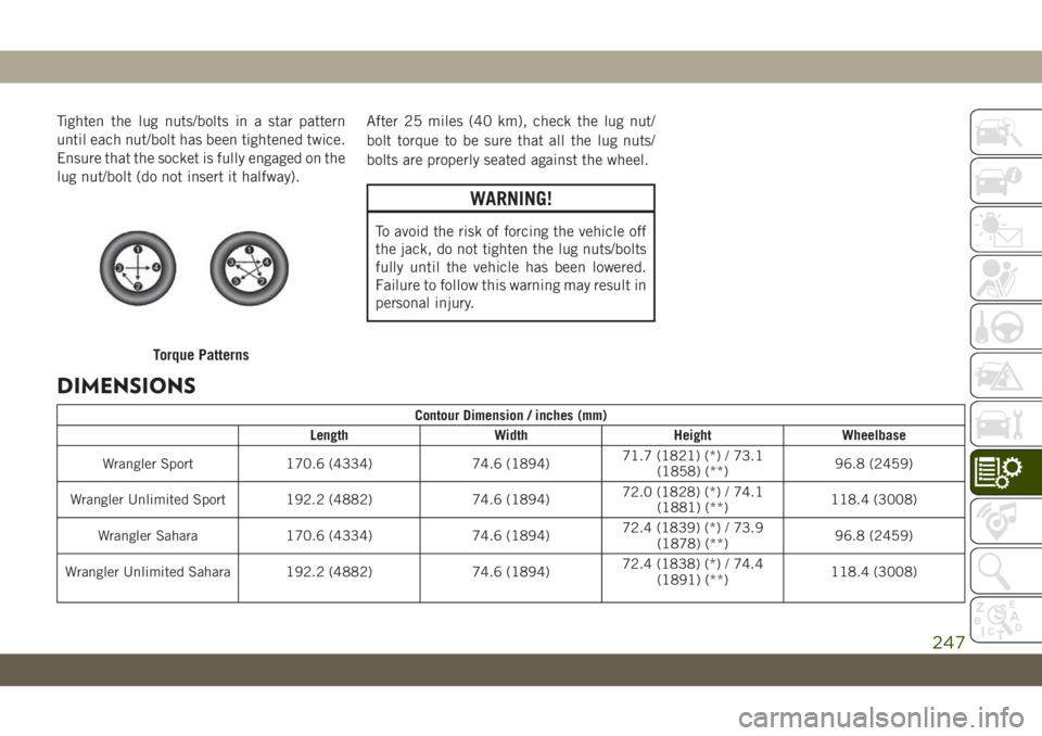
Tighten the lug nuts/bolts in a star pattern
until each nut/bolt has been tightened twice.
Ensure that the socket is fully engaged on the
lug nut/bolt (do not insert it halfway).After 25 miles (40 km), check the lug nut/
bolt torque to be sure that all the lug nuts/
bolts are properly seated against the wheel.
WARNING!
To avoid the risk of forcing the vehicle off
the jack, do not tighten the lug nuts/bolts
fully until the vehicle has been lowered.
Failure to follow this warning may result in
personal injury.
DIMENSIONS
Contour Dimension / inches (mm)
Length Width Height Wheelbase
Wrangler Sport 170.6 (4334) 74.6 (1894)71.7 (1821) (*) / 73.1
(1858) (**)96.8 (2459)
Wrangler Unlimited Sport 192.2 (4882) 74.6 (1894)72.0 (1828) (*) / 74.1
(1881) (**)118.4 (3008)
Wrangler Sahara 170.6 (4334) 74.6 (1894)72.4 (1839) (*) / 73.9
(1878) (**)96.8 (2459)
Wrangler Unlimited Sahara 192.2 (4882) 74.6 (1894)72.4 (1838) (*) / 74.4
(1891) (**)118.4 (3008)
Torque Patterns
247