warning light JEEP WRANGLER UNLIMITED 2019 Owner handbook (in English)
[x] Cancel search | Manufacturer: JEEP, Model Year: 2019, Model line: WRANGLER UNLIMITED, Model: JEEP WRANGLER UNLIMITED 2019Pages: 348, PDF Size: 6.5 MB
Page 163 of 348
NOTE:
• In order to ensure proper operation, the
Speed Control System has been designed
to shut down if multiple Speed Control
functions are operated at the same time. If
this occurs, the Speed Control System can
be reactivated by pushing the Speed Con-
trol on/off button and resetting the desired
vehicle set speed.
• Do not place the gear selector in neutral
when Speed Control is activated. Doing so
will disengage the system.
WARNING!
Speed Control can be dangerous where the
system cannot maintain a constant speed.
Your vehicle could go too fast for the con-
ditions, and you could lose control and
have an accident. Do not use Speed Con-
trol in heavy traffic or on roads that are
winding, icy, snow-covered or slippery.
To Activate
Push the on/off button to activate the Speed
Control. The cruise indicator light in the in-
strument cluster display will illuminate. Toturn the system off, push the on/off button a
second time. The cruise indicator light will
turn off. The system should be turned off
when not in use.
WARNING!
Leaving the Speed Control system on when
not in use is dangerous. You could acci-
dentally set the system or cause it to go
faster than you want. You could lose con-
trol and have an accident. Always leave the
system off when you are not using it.
To Set A Desired Speed
Turn the Speed Control on.
NOTE:
The vehicle should be traveling at a steady
speed and on level ground before pushing the
SET (+) or SET (-) button.
When the vehicle has reached the desired
speed, push the SET (+) or SET (-) button and
release. Release the accelerator and the ve-
hicle will operate at the selected speed.
To Vary The Speed Setting
To Increase Speed
When the Speed Control is set, you can in-
crease speed by pushing the SET(+)button.
The driver’s preferred units can be selected
through the instrument panel settings. Refer
to ”Instrument Cluster Display” in “Getting
To Know Your Instrument Panel” in your Own-
er’s Manual for more information. The speed
increment shown is dependent on the chosen
speed unit of U.S. (mph) or Metric (km/h):
U.S. Speed (mph)
• Pushing the SET(+)button once will result
in a 1 mph increase in set speed. Each
subsequent tap of the button results in an
increase of 1 mph.
• If the button is continually pushed, the set
speed will continue to increase until the
button is released, then the new set speed
will be established.
161
Page 164 of 348
Metric Speed (km/h)
• Pushing the SET(+)button once will result
in a 1 km/h increase in set speed. Each
subsequent tap of the button results in an
increase of 1 km/h.
• If the button is continually pushed, the set
speed will continue to increase until the
button is released, then the new set speed
will be established.
To Decrease Speed
When the Speed Control is set, you can de-
crease speed by pushing the SET(-)button.
The driver’s preferred units can be selected
through the instrument panel settings. Refer
to ”Instrument Cluster Display” in “Getting
To Know Your Instrument Panel” in your Own-
er’s Manual for more information. The speed
increment shown is dependent on the chosen
speed unit of U.S. (mph) or Metric (km/h):
U.S. Speed (mph)
• Pushing the SET(-)button once will result
in a 1 mph decrease in set speed. Each
subsequent tap of the button results in a
decrease of 1 mph.• If the button is continually pushed, the set
speed will continue to decrease until the
button is released, then the new set speed
will be established.
Metric Speed (km/h)
• Pushing the SET(-)button once will result
in a 1 km/h decrease in set speed. Each
subsequent tap of the button results in a
decrease of 1 km/h.
• If the button is continually pushed, the set
speed will continue to decrease until the
button is released, then the new set speed
will be established.
To Accelerate For Passing
Press the accelerator as you would normally.
When the pedal is released, the vehicle will
return to the set speed.
Using Speed Control On Hills
The transmission may downshift on hills to
maintain the vehicle set speed.
NOTE:
The Speed Control system maintains speed
up and down hills. A slight speed change on
moderate hills is normal.On steep hills, a greater speed loss or gain
may occur so it may be preferable to drive
without Speed Control.
WARNING!
Speed Control can be dangerous where the
system cannot maintain a constant speed.
Your vehicle could go too fast for the con-
ditions, and you could lose control and
have an accident. Do not use Speed Con-
trol in heavy traffic or on roads that are
winding, icy, snow-covered or slippery.
To Resume Speed
To resume a previously set speed, push the
RES button and release. Resume can be used
at any speed above 20 mph (32 km/h).
To Deactivate
A soft tap on the brake pedal, pushing the
CANC (cancel) button, or normal brake pres-
sure while slowing the vehicle will deactivate
the speed control without erasing the set
speed from memory.
STARTING AND OPERATING
162
Page 168 of 348
CAUTION!
• To avoid vehicle damage, ParkView
should only be used as a parking aid.
The ParkView camera is unable to view
every obstacle or object in your drive
path.
• To avoid vehicle damage, the vehicle
must be driven slowly when using
ParkView to be able to stop in time when
an obstacle is seen. It is recommended
that the driver look frequently over his/
her shoulder when using ParkView.
NOTE:
If snow, ice, mud, or any foreign substance
builds up on the camera lens, clean the lens,
rinse with water, and dry with a soft cloth. Do
not cover the lens.
REFUELING THE VEHICLE
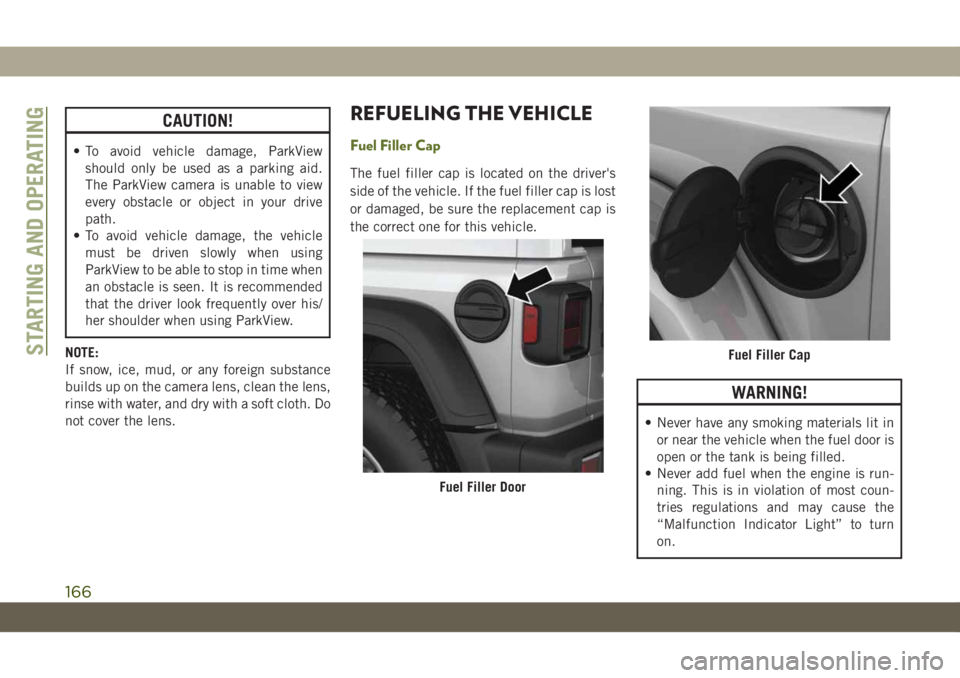
Fuel Filler Cap
The fuel filler cap is located on the driver's
side of the vehicle. If the fuel filler cap is lost
or damaged, be sure the replacement cap is
the correct one for this vehicle.
WARNING!
• Never have any smoking materials lit in
or near the vehicle when the fuel door is
open or the tank is being filled.
• Never add fuel when the engine is run-
ning. This is in violation of most coun-
tries regulations and may cause the
“Malfunction Indicator Light” to turn
on.
Fuel Filler Door
Fuel Filler CapSTARTING AND OPERATING
166
Page 169 of 348
WARNING!
• Do not apply any object/cap to the end of
the filler which is not provided for the
car. The use of non-compliant objects/
plugs could cause a pressure increase
inside the tank, resulting in dangerous
situations.
• A fire may result if fuel is pumped into a
portable container that is inside of a
vehicle. You could be burned. Always
place fuel containers on the ground
while filling.
CAUTION!
• Damage to the fuel system or emission
control system could result from using
an improper fuel filler cap. A poorly
fitting cap could let impurities into the
fuel system. Also, a poorly fitting after-
market cap can cause the “Malfunction
Indicator Light (MIL)” to illuminate, due
to fuel vapors escaping from the system.
• To avoid fuel spillage and overfilling, do
not “top off” the fuel tank after filling.NOTE:
• When the fuel nozzle “clicks” or shuts off,
the fuel tank is full.
• Tighten the fuel filler cap about 1/4 turn
until you hear one click. This is an indica-
tion that the cap is properly tightened.
• If the fuel filler cap is not tightened prop-
erly, the MIL will come on. Be sure the cap
is tightened every time the vehicle is
refueled.
Loose Fuel Filler Cap Message
After fuel has been added, the vehicle diag-
nostic system can determine if the fuel filler
cap is possibly loose, improperly installed, or
damaged. If the system detects a malfunc-
tion, the “gASCAP” message will display in
the odometer display. Tighten the gas cap
until a "clicking" sound is heard. This is an
indication that the gas cap is properly tight-
ened. Push the odometer reset button to turn
the message off. If the problem persists, the
message will appear the next time the vehicle
is started. This might indicate a damagedcap. If the problem is detected twice in a row,
the system will turn on the MIL. Resolving the
problem will turn the MIL off.
REFUELING THE VEHICLE —
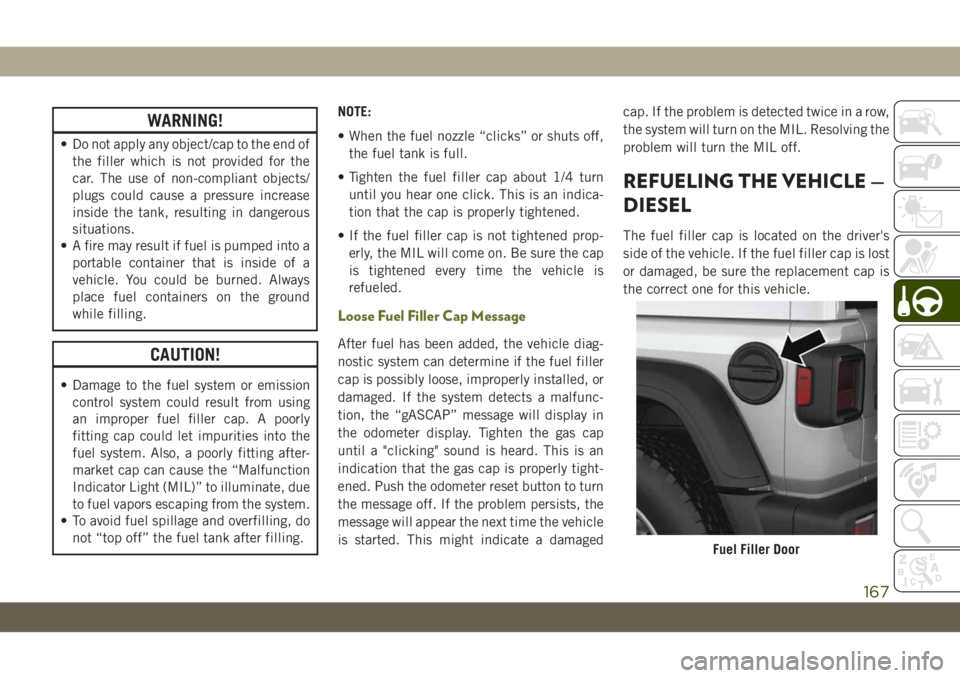
DIESEL
The fuel filler cap is located on the driver's
side of the vehicle. If the fuel filler cap is lost
or damaged, be sure the replacement cap is
the correct one for this vehicle.
Fuel Filler Door
167
Page 170 of 348
WARNING!
• Never have any smoking materials lit in
or near the vehicle when the fuel door is
open or the tank is being filled.
• Never add fuel when the engine is run-
ning. This is in violation of most coun-
tries regulations and may cause the
“Malfunction Indicator Light” to turn
on.
WARNING!
• Do not apply any object/cap to the end of
the filler which is not provided for the
car. The use of non-compliant objects/
plugs could cause a pressure increase
inside the tank, resulting in dangerous
situations.
• A fire may result if fuel is pumped into a
portable container that is inside of a
vehicle. You could be burned. Always
place fuel containers on the ground
while filling.
CAUTION!
• Damage to the fuel system or emission
control system could result from using
an improper fuel filler cap. A poorly
fitting cap could let impurities into the
fuel system. Also, a poorly fitting after-
market cap can cause the “Malfunction
Indicator Light (MIL)” to illuminate, due
to fuel vapors escaping from the system.
• To avoid fuel spillage and overfilling, do
not “top off” the fuel tank after filling.NOTE:
• When the fuel nozzle “clicks” or shuts off,
the fuel tank is full.
• Tighten the fuel filler cap about 1/4 turn
until you hear one click. This is an indica-
tion that the cap is properly tightened.
• If the fuel filler cap is not tightened prop-
erly, the MIL will come on. Be sure the cap
is tightened every time the vehicle is
refueled.
Adblue (UREA) — If Equipped
The vehicle is equipped with an UREA injec-
tion system and Selective Catalytic Reduc-
tion to meet emission standards. These two
systems ensure compliance with the diesel
emissions requirements; at the same, they
ensure fuel-efficiency, handling, torque and
power. For messages and system warnings,
refer to the "Warning Lights And Messages" in
the "Getting To Know Your Instrument Panel"
section. AdBlue (UREA) is a very stable prod-
uct with a long shelf life. Stored at tempera-
tures LOWER than 90 °F (32 °C), it has a
shelf life of at least one year. For more infor-
mation on the AdBlue liquid type, see the
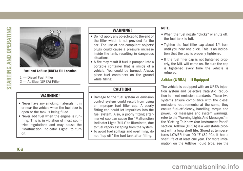
Fuel and AdBlue (UREA) Fill Location
1 — Diesel Fuel Filler
2 — AdBlue (UREA) Filler
STARTING AND OPERATING
168
Page 171 of 348
“Fluids and lubricants” in the “Technical
specifications” section. The vehicle is
equipped with an automatic AdBlue heating
system when the engine starts allowing the
system to work correctly at temperatures
lower than 12 °F (-11 °C).
NOTE:
AdBlue freezes at temperatures lower than
12 °F (-11 °C).
AdBlue (UREA) Storage
AdBlue (UREA) is considered a very stable
product with a long shelf life. If AdBlue
(UREA) is kept in temperatures between
10° and 90°F (-12° and 32°C), it will last a
minimum of one year.
AdBlue (UREA) is subject to freezing at the
lowest temperatures. For example, AdBlue
(UREA) may freeze at temperatures at or
below 12° F (-11° C). The system has been
designed to operate in this environment.NOTE:
When working with AdBlue (UREA), it is
important to know that:
• Any containers or parts that come into con-
tact with AdBlue (UREA) must be AdBlue
(UREA) compatible (plastic or stainless
steel). Copper, brass, aluminum, iron or
non-stainless steel should be avoided as
they are subject to corrosion by AdBlue
(UREA).
• If AdBlue (UREA) is spilled, it should be
wiped up completely.
Adding AdBlue (UREA)
Preliminary Conditions
AdBlue (UREA) freezes at temperatures
lower than 12° F (-11° C). If the car stands for
a long time at this temperature refilling could
be difficult. For this reason, it is advised to
park the vehicle in a garage and/or heated
environment and wait for the urea to return to
liquid state before topping up.
Proceed as follows:
• Park the car on flat ground and stop the
engine by cycling the ignition to the OFF
position.• Open the fuel door, undo and remove the
cap (blue) from the AdBlue (UREA) filler.
Refilling With Nozzles
You can fill up at any AdBlue (UREA) dis-
tributor.
Proceed as follows:
• Insert the AdBlue (UREA) nozzle in the
filler, start refilling and stop refilling at the
first shut-off (the shut-off indicates that the
AdBlue (UREA) tank is full). Do not pro-
ceed with the refilling, to prevent spillage
of AdBlue (UREA).
• Extract the nozzle.
Refilling With Containers
Proceed as follows:
• Check the expiration date.
• Read the advice for use on the label before
pouring the content of the bottle into the
AdBlue (UREA) tank.
• If systems which cannot be screwed in (e.g.
tanks) are used for refilling, after the indi-
cation appears on the instrument panel
display refer to “Warning lights And Mes-
sages" in the “Getting To Know Your Instru-
169
Page 172 of 348
ment Panel” for further information, fill the
AdBlue (UREA) tank with no more than
2 Gallons (8 liters).
• If containers which can be screwed to the
filler are used, the reservoir is full when the
AdBlue (UREA) level in the container stops
pouring out. Do not proceed further.
Operations After Refilling
Proceed as follows:
• Fit the cap back on the AdBlue (UREA)
filler by turning it clockwise and screwing it
completely.
• Cycle the ignition to RUN (it is not neces-
sary to start the engine).
• Wait for the indication on the instrument
panel to switch off before moving the car.
The indication may stay on for a few sec-
onds to approximately half a minute. If the
engine is started and the car is moved, the
indication will remain on for longer. This
will not compromise engine operation.• If the AdBlue (UREA) was topped up when
the tank was empty, wait for 2 minutes
before starting the engine.
NOTE:
• If AdBlue (UREA) is spilled out of the filler
neck, clean up well the area and proceed to
filling up again. If the liquid crystallizes,
eliminate it with a sponge and warm water.
• DO NOT EXCEED THE MAXIMUM LEVEL:
this could cause damage to the reservoir.
AdBlue (UREA) freezes at under 12° F
(-11° C). Although the system is designed
to operate below the freezing point of the
UREA, it is advisable not to fill the tank
beyond the maximum level because if the
UREA freezes the system can be damaged.
Follow the instructions in this section.
• If the AdBlue (UREA) is spilled on painted
surfaces or aluminium, immediately clean
the area with water and use absorbent ma-
terial to collect the fluid that has been
spilled on the ground.• Do not try to start the engine if AdBlue
(UREA) was accidentally added to the die-
sel fuel tank, this can result in serious
engine damage, contact an authorized
dealer.
• Do not add additives or other fluids to
AdBlue (UREA), doing so could damage the
system.
• The use of non-conforming or degraded
AdBlue (UREA) may lead to indications
appearing on the instrument panel display
refer to “Warning Lights And Messages" in
the “Getting To Know Your Instrument
Panel” for further information.
• Never pour AdBlue (UREA) into another
container: it could be contaminated.
• If the AdBlue (UREA) runs out, see refer to
“Warning Lights And Messages" in the
“Getting To Know Your Instrument Panel”
for further information to continue using
the car normally.
STARTING AND OPERATING
170
Page 195 of 348
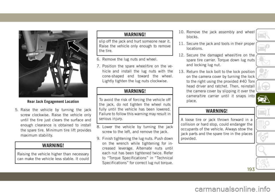
5. Raise the vehicle by turning the jack
screw clockwise. Raise the vehicle only
until the tire just clears the surface and
enough clearance is obtained to install
the spare tire. Minimum tire lift provides
maximum stability.
WARNING!
Raising the vehicle higher than necessary
can make the vehicle less stable. It could
WARNING!
slip off the jack and hurt someone near it.
Raise the vehicle only enough to remove
the tire.
6. Remove the lug nuts and wheel.
7. Position the spare wheel/tire on the ve-
hicle and install the lug nuts with the
cone-shaped end toward the wheel.
Lightly tighten the lug nuts clockwise.
WARNING!
To avoid the risk of forcing the vehicle off
the jack, do not tighten the wheel nuts
fully until the vehicle has been lowered.
Failure to follow this warning may result in
serious injury.
8. Lower the vehicle by turning the jack
screw to the left, and remove the jack.
9. Finish tightening the lug nuts. Push down
on the wrench while tightening for in-
creased leverage. Alternate nuts until
each nut has been tightened twice. Refer
to “Torque Specifications” in “Technical
Specifications” for correct lug nut torque.10. Remove the jack assembly and wheel
blocks.
11. Secure the jack and tools in their proper
locations.
12. Secure the damaged wheel/tire on the
spare tire carrier. Torque down lug nuts
and locking lug nut.
13. Return the lock bolt to the lock position
on the camera cover by turning the lock
to the right using the provided #40 Torx
head driver and ratchet. Then, reinstall
the camera cover by slipping it over the
camera/tire carrier until it snaps into
place.
WARNING!
A loose tire or jack thrown forward in a
collision or hard stop, could endanger the
occupants of the vehicle. Always stow the
jack parts and the spare tire in the places
provided.
Rear Jack Engagement Location
193
Page 196 of 348
Road Tire Installation
1. Mount the road tire on the axle.
2. Install the remaining lug nuts with the
cone shaped end of the nut toward the
wheel. Lightly tighten the lug nuts.
WARNING!
To avoid the risk of forcing the vehicle off
the jack, do not tighten the wheel nuts
fully until the vehicle has been lowered.
Failure to follow this warning may result in
serious injury.
3. Lower the vehicle to the ground by turning
the jack handle counterclockwise.
4. Finish tightening the lug nuts. Push down
on the wrench while at the end of the
handle for increased leverage. Tighten the
lug nuts in a star pattern until each nut
has been tightened twice. For the correct
lug nut torque refer to “Torque Specifica-
tions” in “Technical Specifications”. If in
doubt about the correct tightness, have
them checked with a torque wrench by an
authorized dealer or service station.5. After 25 miles (40 km), check the lug nut
torque with a torque wrench to ensure that
all lug nuts are properly seated against the
wheel.
Declaration Of Conformance
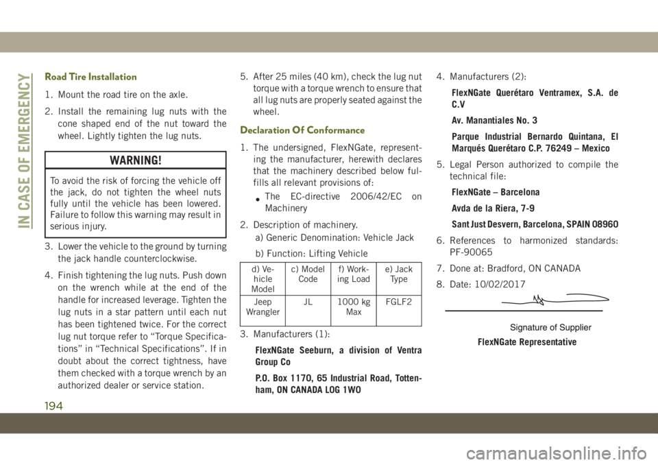
1. The undersigned, FlexNGate, represent-
ing the manufacturer, herewith declares
that the machinery described below ful-
fills all relevant provisions of:
•The EC-directive 2006/42/EC on
Machinery
2. Description of machinery.
a) Generic Denomination: Vehicle Jack
b) Function: Lifting Vehicle
d) Ve-
hicle
Modelc) Model
Codef) Work-
ing Loade) Jack
Type
Jeep
WranglerJL 1000 kg
MaxFGLF2
3. Manufacturers (1):
FlexNGate Seeburn, a division of Ventra
Group Co
P.O. Box 1170, 65 Industrial Road, Totten-
ham, ON CANADA L0G 1W04. Manufacturers (2):
FlexNGate Querétaro Ventramex, S.A. de
C.V
Av. Manantiales No. 3
Parque Industrial Bernardo Quintana, El
Marqués Querétaro C.P. 76249 – Mexico
5. Legal Person authorized to compile the
technical file:
FlexNGate – Barcelona
Avda de la Riera, 7-9
Sant Just Desvern, Barcelona, SPAIN 08960
6. References to harmonized standards:
PF-90065
7. Done at: Bradford, ON CANADA
8. Date: 10/02/2017FlexNGate Representative
IN CASE OF EMERGENCY
194
Page 214 of 348
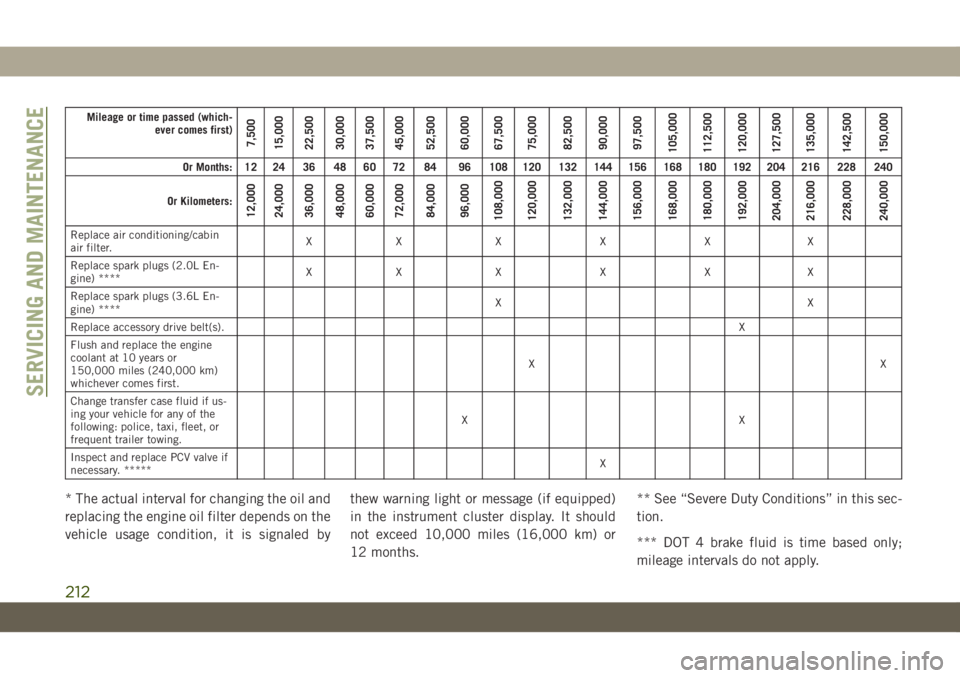
Mileage or time passed (which-
ever comes first)
7,500
15,000
22,500
30,000
37,500
45,000
52,500
60,000
67,500
75,000
82,500
90,000
97,500
105,000
112,500
120,000
127,500
135,000
142,500
150,000
Or Months: 12 24 36 48 60 72 84 96 108 120 132 144 156 168 180 192 204 216 228 240
Or Kilometers:
12,000
24,000
36,000
48,000
60,000
72,000
84,000
96,000
108,000
120,000
132,000
144,000
156,000
168,000
180,000
192,000
204,000
216,000
228,000
240,000
Replace air conditioning/cabin
air filter.XX X X X X
Replace spark plugs (2.0L En-
gine) ****XX X X X X
Replace spark plugs (3.6L En-
gine) ****XX
Replace accessory drive belt(s).X
Flush and replace the engine
coolant at 10 years or
150,000 miles (240,000 km)
whichever comes first.XX
Change transfer case fluid if us-
ing your vehicle for any of the
following: police, taxi, fleet, or
frequent trailer towing.XX
Inspect and replace PCV valve if
necessary. *****X
* The actual interval for changing the oil and
replacing the engine oil filter depends on the
vehicle usage condition, it is signaled bythew warning light or message (if equipped)
in the instrument cluster display. It should
not exceed 10,000 miles (16,000 km) or
12 months.** See “Severe Duty Conditions” in this sec-
tion.
*** DOT 4 brake fluid is time based only;
mileage intervals do not apply.
SERVICING AND MAINTENANCE
212