headlamp JEEP XJ 1995 Service And Owners Manual
[x] Cancel search | Manufacturer: JEEP, Model Year: 1995, Model line: XJ, Model: JEEP XJ 1995Pages: 2158, PDF Size: 81.9 MB
Page 1191 of 2158
When the park lamp relay energizes, the relay con-
tacts close and connect circuit F81 from fuse 6 in the
fuse block to circuit L36. Circuit L36 connects to the
contact side of the high beam relay. The contacts in
the high beam relay are normally closed. Battery
voltage flows through high beam relay to the fog
lamps on circuit L39. Circuit L39 also splices to the
lamp in the fog lamp switch.
Circuit L3 from the dimmer switch provides power
for the high beams of the headlamps and connects to
Circuit G34. Circuit G34 powers the coil side of the
high beam relay. Circuit Z1 provides ground for the
coil. When the operator selects high beam operation
or flashes the optical horn, circuit G34 energizes the
high beam relay. When energized, the normally
closed contacts in the relay open, shutting off battery
voltage to the fog lamps on circuit L39.
HELPFUL INFORMATION
²Circuit A6 from fuse 3 in the PDC supplies voltage
to the fuse block for fuses in cavities 3 and 6. Fuse 6
in the fuse block protects circuit F81 which powers
the contact side of the park lamp relay.
²In the high beam position, the dimmer switch con-
nects circuit L20 from the headlamp switch to circuit
L3. The headlamp switch connects circuit A3 from
fuse 7 in the PDC with circuit L20. Circuits A3 and
L20 are HOT at all times.
DAYTIME RUNNING LAMP (DRL) MODULEÐ
CANADIAN VEHICLES ONLY
On Canadian vehicles, the low-beam headlamps op-
erate when the ignition switch is in the RUN position
and the headlamp switch is OFF.
When the ignition switch is in the START or RUN
positions, circuit A1 from fuse 4 in the Power Distri-
bution Center (PDC) connects to circuit A21. Circuit
A21 supplies voltage to circuit G5 through fuse 9 in
the fuse block. Circuit G5 splices to supply battery
voltage to the DRL module.
Circuit L20 from the headlamp switch connects to
the DRL module. Circuit L20 is HOT at all times.
The DRL module receives the vehicle speed sensor
input from circuit G7. Circuit G34 from the DRLmodule provides power for the high beam indicator
lamp in the instrument cluster.
Circuit L4 feeds the low beams of the headlamps.
When the headlamp switch is in the OFF position,
the DRL module powers the left and right headlamps
on circuit L4. When the headlamps are ON, the dim-
mer switch powers the low beams on circuit L4.
Circuit L3 feeds the high beams of the headlamps.
When the operator flashes the high beams with the
turn signal stalk, the DRL senses voltage on circuit
L3. When it senses voltage on circuit L3, the DRL
module stops supplying power to the low beams on
circuit L4.
Circuit Z1 provides ground for the DRL module.
Circuit Z1 terminates at the radiator left side sup-
port.
DIAGRAM INDEX
Component Page
Daytime Running Lamp (DRL) Module. . . .8W-50-3, 7, 9, 11
Fog Lamps.............................8W-50-9
Fog Lamp Switch........................8W-50-9
Fuse 3 (PDC)...........................8W-50-3
Fuse 4 (PDC)..........................8W-50-10
Fuse 6 (Fuse Block).......................8W-50-8
Fuse 7 (PDC)........................8W-50-3, 10
Fuse 8 (Fuse Block).......................8W-50-3
Fuse 9 (Fuse Block)......................8W-50-10
Headlamp Switch....................8W-50-3, 8, 10
Headlamp Dimmer Switch.................8W-50-3, 8
High Beam Relay.........................8W-50-9
Ignition Switch.........................8W-50-10
Instrument Cluster..................8W-50-3 thru 10
Left Headlamp.........................8W-50-4, 6
Left Park, Turn Signal Lamp...............8W-50-4, 6
Left Side Marker Lamp...................8W-50-4, 6
Park Lamp Relay.........................8W-50-8
Powertrain Control Module..................8W-50-11
Right Headlamp........................8W-50-5, 7
Right Park, Turn Signal Lamp..............8W-50-5, 7
Right Side Marker Lamp..................8W-50-5, 7
8W - 50 - 2 8W-50 FRONT LIGHTINGÐYJ VEHICLESJ
Page 1202 of 2158
REAR LIGHTING
TAIL LAMPS AND LICENSE PLATE LAMPS
Circuit A6 in the Power Distribution Center (PDC)
connects to a bus bar in the fuse block. The fuse
block bus bar powers circuit F33. Circuit F33 con-
nects to the headlamp switch. Fuse 3 in the PDC
protects circuit A3. Fuse 8 in the fuse block protects
circuit F33.
The headlamp switch has three positions: ON,
PARK (parking lamps) and OFF, plus a dimmer
switch. When the headlamp switch is in the PARK or
ON position, the switch connects circuit F33 to cir-
cuit L7. From the headlamp switch, circuit L7
branches to power the front parking lamps and rear
tail and license plate lamps. The lamps are case
grounded.
HELPFUL INFORMATION
²If the vehicle is equipped with factory installed fog
lamps, circuit L7 splices to feed the park lamp relay.
²Jumper harnesses connect the tail, stop, turn sig-
nal lamp to the body harness.
²Check fuse 3 in the PDC.
²Check fuse 8 in the fuse block.
²Circuit L7 also feeds the radio, if equipped.
STOP LAMPS AND CHMSL LAMPS
Circuit A6 from fuse 3 in the Power Distribution
Center (PDC) supplies voltage to the fuse block bus
bar. The bus bar powers circuit F32 through fuse 3 in
the fuse block. Circuit F32 connects to the stop lamp
switch.
When the operator depresses the brake pedal, the
stop lamp switch closes, and connects circuit F32 to
circuit L50. Circuit L50 connects to the CHMSL
lamps and turn signal/hazard flasher. Circuit Z1 pro-
vides ground for the CHMSL lamps. The turn signal/
hazard flasher supplies current to the L62 and L63
circuits. Circuit L62 powers the right stop lamp. Cir-
cuit L63 powers the left stop lamp. The stop lamps
are case grounded.
HELPFUL INFORMATION
²Circuits L50 and Z1 pass through contacts in the
rear door before reaching the CHMSL lamps.
²Check fuse 3 in the PDC.²Check fuse 3 in the fuse block.
²Check for continuity across the stop lamp switch
when it is closed.
²If the vehicle is equipped with anti-lock brakes,
circuit L50 connects to the ABS module.
BACK-UP LAMPS
In the START or RUN position, the ignition switch
connects circuit A1 from fuse 4 in the Power Distri-
bution Center (PDC) to circuit A21. Circuit A21 feeds
a bus bar in the fuse block that powers circuit G5
through fuse 9.
Circuit G5 splices to supply power to the back-up
lamp switch. On automatic transmission vehicles, the
back-up lamp switch is part of an assembly that in-
cludes the PARK/NEUTRAL position switch.
When the operator puts the transmission in Re-
verse, the back-up lamp switch connects circuit G5 to
circuit L1. Circuit L1 feeds the case grounded
back-up lamps.
HELPFUL INFORMATION
²Check fuse 4 in the PDC.
²Check fuse 9 in the fuse block.
²Check for continuity across the back-up lamp
switch when it is closed.
DIAGRAM INDEX
Component Page
ABS Control Module......................8W-51-3
Back-Up Lamps..........................8W-51-4
Back-Up Lamp Switch.....................8W-51-2
Center High Mounted Stop Lamps (CHMSL).......8W-51-3
Fuse 3 (Fuse Block).......................8W-51-2
Fuse 3 (PDC)...........................8W-51-2
Fuse 4 (PDC)...........................8W-51-2
Fuse 9 (Fuse Block).......................8W-51-2
Fuse 8 (Fuse Block).......................8W-51-2
Headlamp Switch.........................8W-51-2
Ignition Switch..........................8W-51-2
Powertrain Control Module..................8W-51-3
Stop Lamp Switch........................8W-51-3
Tail, Stop, and Turn Signal Lamps.............8W-51-4
J8W-51 REAR LIGHTINGÐYJ VEHICLES 8W - 51 - 1
Page 1262 of 2158
CONNECTOR LOCATIONS
GENERAL INFORMATION
This section provides illustrations identifying com-
ponent and connector locations in the vehicle. A con-nector index is provided. Use the wiring diagrams in
each section for connector number identification. Re-
fer to the index for the proper figure number.
CONNECTOR LOCATIONS
Connector # . Color . Location Fig.
C101......BK ...RTFender Side Shield..........1
C102......BK ...RTFender Side Shield Under PDC . .1
C103......BK ...RTFender Side Shield..........1
C104......BK ...LTSide of Battery on Cowl Panel . . .1
C105 2.5L . . . NAT . . RT Rear of Engine............3
C105 4.0L . . . NAT . . RT Rear of Engine............4
C106......BK ...AtLamp...................1
C107......NAT ..Center of Cowl Panel Near
Map Sensor...............1
C108......BK ...LTKick Panel Above Park Brake . . .8
C109......BK ...Under Drivers Seat............8
C110......BK ...Under I.P.Front of Floor Tunnel....6
C111......BK ...Under I.P.Front of Floor Tunnel....6
C112......BK ...Under I.P. RT of Stop Lamp Switch .7
C113......BK ...LTFender Side Shield..........1
C114......BK ...LTSide Cowl Panel............1
C115......BK ...LTFender Side Shield..........1
C116......BK ...LTFender Side Shield..........1
C117......BK ...LTFender Side Shield..........1
C118......BK ...Bottom of Washer Reservoir......2
C119......BK ...Near Bulkhead Disconnect
2.5L only..........Not Shown
C120 2.5L . . . BK . . . Rear of Generator.............3
C120 4.0L . . . BK . . . Rear of Generator.............5
C121 2.5L . . . BK . . . RT Rear of Engine............3
C121 4.0L . . . BK . . . Rear of Generator.............4
C122......BK ...OnReceiver/Drier.............4
C123 2.5L . . . BK . . . RT Side of Engine Rear of Distributor .3
C123 4.0L . . . BK . . . RT Side of Engine Rear of Distributor .4
C124 2.5L . . . BK . . . At End of Distributor Pig Tail.....3
C124 4.0L . . . BK . . . At End of Distributor Pig Tail.....4
C125......GY ...RTSide of Transmission........5
C126......BK ...LTRear of Transmission.........5
C127......BK ...TopofFuel Tank..............9
C128......BK ...TopofRear Cross-member.......9
C129......BK ...TopofRear Cross-member.......9
C130 2.5L . . . BK . . . On Thermostat Housing.........3
C130 4.0L . . . BK . . . On Thermostat Housing.........4
C131 2.5L . . . BK . . . LT Side of Engine Bottom of Intake .3
C131 4.0L . . . BK . . . LT Side of Engine Bottom of Intake .4
C132 2.5L . . . BK . . . Injector #1.................3
C132 4.0L . . . BK . . . Injector #1.................4
C133 2.5L . . . BK . . . Injector #2.................3
C133 4.0L . . . BK . . . Injector #2.................4
C134 2.5L . . . BK . . . Injector #3.................3
C134 4.0L . . . BK . . . Injector #3.................4
C135 2.5L . . . BK . . . Injector #4.................3
C135 4.0L . . . BK . . . Injector #4.................4Connector # . Color . Location Fig.
C136......BK ...Injector #5.................4
C137......BK ...Injector #6.................4
C138 2.5L . . . BK . . . Center of Dash Panel...........1
C138 4.0L . . . BK . . . Center of Dash Panel...........1
C139......BK ...Under Bulkhead LT Side of I.P.....1
C140 2.5L . . . GY . . . LT Rear of Intake.............3
C140 4.0L . . . GY . . . LT Rear of Intake.............4
C141 2.5L . . . BK . . . Rear of Throttle Body..........3
C141 4.0L . . . BK . . . Rear of Throttle Body..........4
C142 2.5L . . . BK . . . On Throttle Body.............3
C142 4.0L . . . BK . . . On Throttle Body.............4
C143 2.5L . . . BK . . . Rear of Intake...............3
C143 4.0L . . . BK . . . Rear of Intake...............4
C144......BK ...Above Bulkhead Disconnect.......1
C145......GY ...OnPower Steering Pump........3
C146......BK ...AtHeadlamp..........Not Shown
C147......YL ...AtSide Marker Lamp..........2
C148......BK ...AtPark/Turn Lamp......Not Shown
C149......BK ...RTSide Behind Bumper.........2
C150......BK ...LTSide Behind Bumper.........2
C151......BK ...AtPark/Turn Lamp............2
C152......YL ...AtSide Marker Lamp. . . .Not Shown
C153......BK ...AtHeadlamp................2
C154......BK ...LTFender Side Shield..........2
C155......BK ...Direct Connection to Horn.......2
C156......BK ...Bottom of Washer Reservoir......2
C201......BK ...LTSide of I.P...............7
C202......BK ...OnFuse Block...............7
C203......BK ...LTKick Panel................7
C204......BK ...LTKick Panel................7
C205......BK ...LTSide Kick Panel Under I.P......7
C206......BK ...AtSpeaker...........Not Shown
C207......BK ...LTofSteering Column Rear
of Cluster.................7
C208......BK ...LTSide of Steering Column......7
C209......BK ...Rear of Switch...............7
C210......BK ...Rear of Switch...............7
C211......BK ...Base of Steering Column........7
C212......BK ...AtWiper Motor..............7
C213......BK ...RTofSteering Column Under I.P. . .7
C214......BK ...RTSide of Cluster Bezel . .Not Shown
C215......BK ...Base of Steering Column........7
C216......BK ...Base of Steering Column........7
C217......BK ...RTSide of Brake Pedal Support . . .7
C218......BK ...Base of Steering Column........7
C219......BK ...Rear of Switch...............7
C220......BK ...Rear of Switch...............7
C221......BK ...Rear of Switch...............7
J8W-90 CONNECTOR LOCATIONSÐYJ VEHICLES 8W - 90 - 1
Page 1273 of 2158
SPLICE LOCATIONS
GENERAL INFORMATION
This section provides illustrations identifying the
general location of the splices in this vehicle. A splice
index is provided. Use the wiring diagrams in each
section for splice number identification. Refer to the
index for the proper splice number.
SPLICE LOCATIONS
Splice
NumberLocations Fig.
S101 Near PDC T/O.....................1
S102 Near T/O for Engine Wiring.............1
S103 RT Dash Panel Near T/o for Ground.......1
S104 Near T/O for MAP Sensor..............1
S105 Near T/O for MAP Sensor..............1
S106 Left Side of MAP Sensor..............1
S107 In ABS Wiring T/O Near Grommet........1
S108 In ABS Wiring T/O Near Grommet........1
S109 Above Brake Booster.................1
S110 Rear of Generator...................3
S111 2.5L RT Side of Valve Cover...............4
S111 4.0L RT Side of Valve Cover...............3
S112 Near T/O for PRNDL Switch............5
S113 Between Inj #2 and Inj #3.............3
S114 Near T/O for Throttle Body Wiring........3
S115 Above Bulkhead Connector.............1
S116 Above Bulkhead Connector.............1
S117 Near Data Link T/O..................1
S118 Near Data Link T/O..................1
S119 Near Data Link T/O..................1
S120 4.0L RT Side of Valve Cover...............3
S121 2.5L RT Side of Valve Cover...............4
S122 Near T/O for RT PK/TURN Lamp.........2
S123 Near T/O for RT Fog Lamp.............2
S124 Near T/O for LT Fog Lamp.............2
S125 Near T/O for LT PK/TURN Lamp.........2Splice
NumberLocations Fig.
S126 Near T/O for Headlamp...............2
S127 Near T/O for Headlamp...............2
S128 Near T/O for Headlamp...............2
S129 Near Horn T/O.....................2
S201 Near T/O for Dimmer Switch............7
S202 Near T/O for Dimmer Switch............7
S203 Near T/O for Dimmer Switch............7
S204 Near T/O for Dimmer Switch............7
S205 Near T/O for Wiper Switch.............7
S206 Near T/O for Wiper Switch.............7
S207 Near Panel Illumination T/O.............7
S208 Near Panel Illumination T/O.............7
S209 Near Panel Illumination T/O.............7
S210 Near Panel Illumination T/O.............7
S211 Near T/O for Ignition Switch............7
S212 Near T/O for Ignition Switch............7
S213 Near T/O for Radio..................6
S301 Near T/O for Park Brake Switch..........8
S302 Near T/O for Park Brake Switch..........8
S303 Near Grommet LT Rear Quarter Panel......8
S304 Near LT Rear Tail Lamp T/O............8
S305 RT Rear Quarter Panel Near Tail Lamp.....8
S306 Near T/O for Dome Lamp.......Not Shown
S307 In CHMSL Jumper Harness......Not Shown
S308 In CHMSL Jumper Harness......Not Shown
J8W-95 SPLICE LOCATIONSÐYJ VEHICLES 8W - 95 - 1
Page 1921 of 2158
EXTERIOR COMPONENTS
INDEX
page page
Air Exhaust GrilleÐXJ...................... 25
Battery TrayÐXJ.......................... 14
Body Side Molding/CladdingÐXJ.............. 20
Body Stripes/DecalsÐXJ.................... 21
Brush GuardÐXJ.......................... 3
Cowl Grille and ScreenÐXJ................. 12
Cowl Weatherstrip Seal/Crossmember Air
DeflectorÐXJ........................... 11
Dash Panel Insulator PanelÐXJ.............. 12
Drip Rail MoldingÐXJ...................... 25
Exterior NameplatesÐXJ................... 26
External MirrorsÐXJ....................... 27
Front FenderÐXJ......................... 14
Fuel Filler Door BumpersÐXJ................ 27Fuel Filler Nozzle/TubeÐXJ................. 26
Grille and Grille Opening Panel (GOP)ÐXJ....... 3
Hood AdjustmentÐXJ...................... 10
Hood Hinge ReplacementÐXJ............... 10
Hood Latch ReplacementÐXJ................ 11
Hood Latch Striker ReplacementÐXJ.......... 11
HoodÐXJ................................ 7
Latch Release Cable ReplacementÐXJ......... 11
Luggage RackÐXJ........................ 28
Quarter Window AppliqueÐXJ................ 25
Radiator Support CrossmemberÐXJ............ 6
Rear Wheelhouse Flares and LinersÐXJ........ 19
Safety Latch Striker ReplacementÐXJ.......... 11
BRUSH GUARDÐXJ
REMOVAL
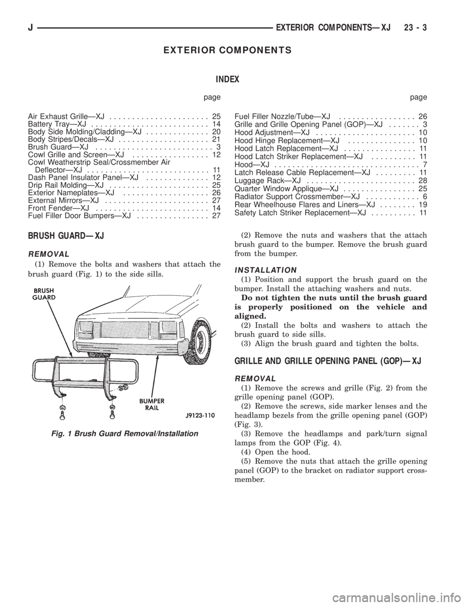
(1) Remove the bolts and washers that attach the
brush guard (Fig. 1) to the side sills.(2) Remove the nuts and washers that the attach
brush guard to the bumper. Remove the brush guard
from the bumper.INSTALLATION
(1) Position and support the brush guard on the
bumper. Install the attaching washers and nuts.
Do not tighten the nuts until the brush guard
is properly positioned on the vehicle and
aligned.
(2) Install the bolts and washers to attach the
brush guard to side sills.
(3) Align the brush guard and tighten the bolts.
GRILLE AND GRILLE OPENING PANEL (GOP)ÐXJ
REMOVAL
(1) Remove the screws and grille (Fig. 2) from the
grille opening panel (GOP).
(2) Remove the screws, side marker lenses and the
headlamp bezels from the grille opening panel (GOP)
(Fig. 3).
(3) Remove the headlamps and park/turn signal
lamps from the GOP (Fig. 4).
(4) Open the hood.
(5) Remove the nuts that attach the grille opening
panel (GOP) to the bracket on radiator support cross-
member.
Fig. 1 Brush Guard Removal/Installation
JEXTERIOR COMPONENTSÐXJ 23 - 3
Page 1922 of 2158
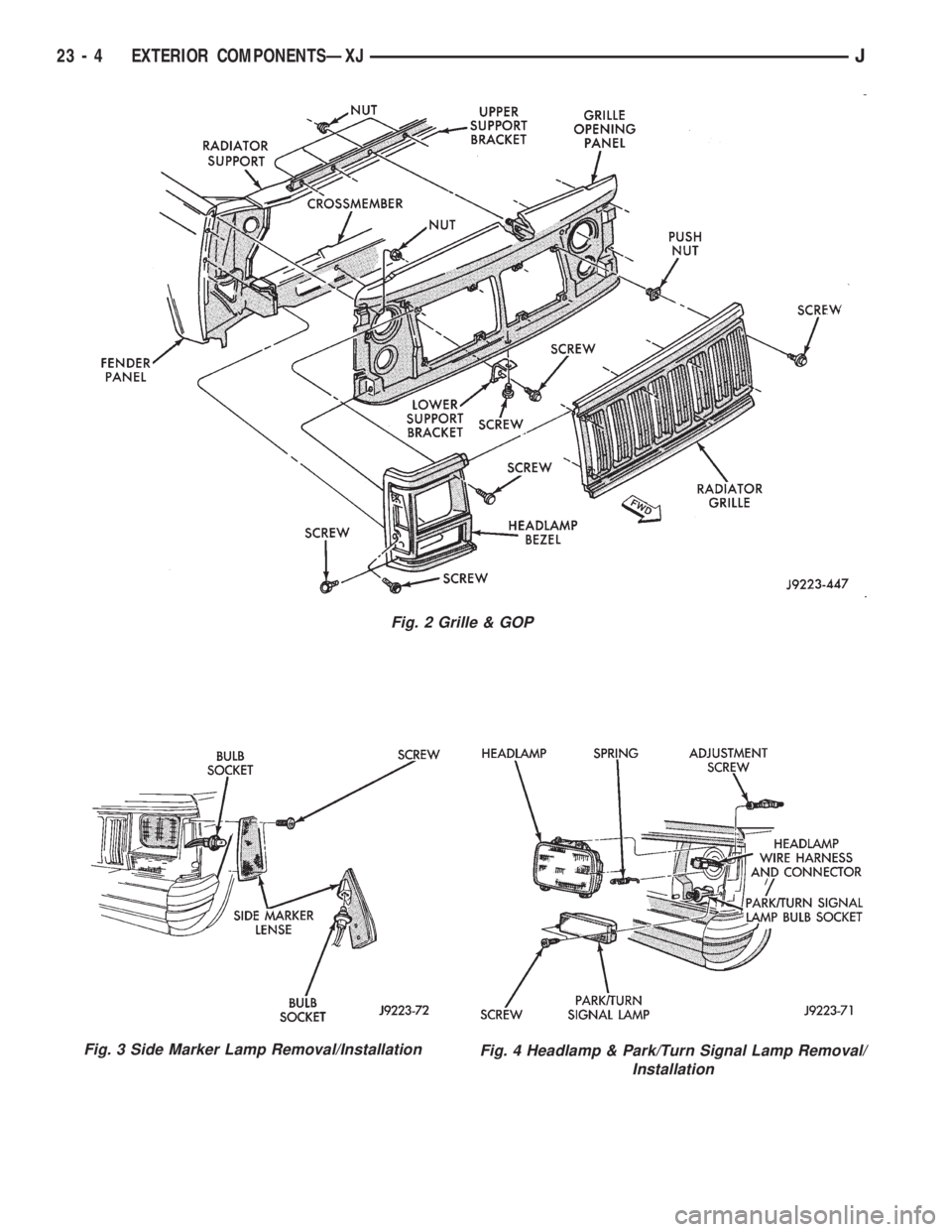
Fig. 2 Grille & GOP
Fig. 3 Side Marker Lamp Removal/InstallationFig. 4 Headlamp & Park/Turn Signal Lamp Removal/
Installation
23 - 4 EXTERIOR COMPONENTSÐXJJ
Page 1923 of 2158
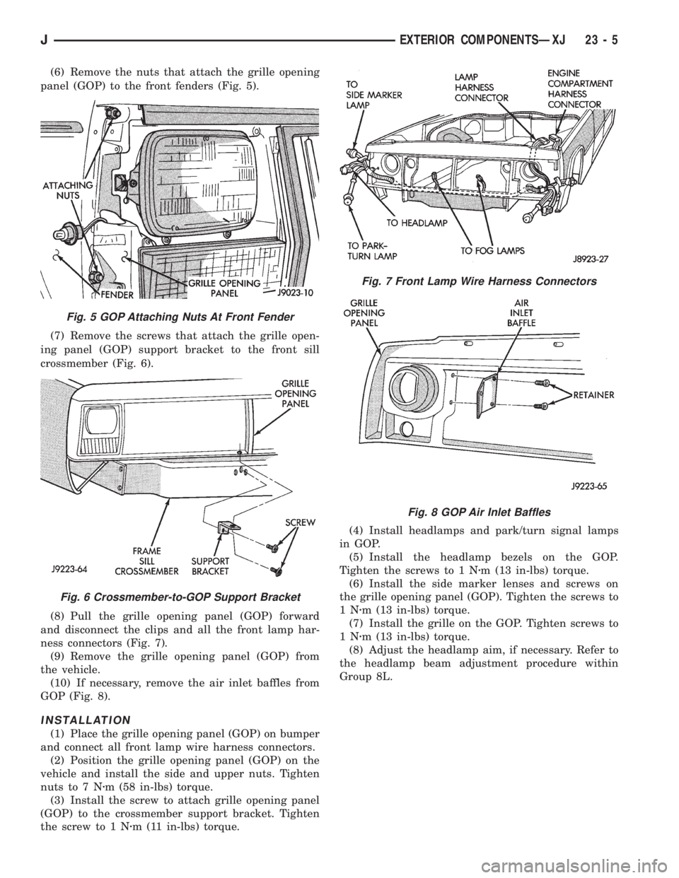
(6) Remove the nuts that attach the grille opening
panel (GOP) to the front fenders (Fig. 5).
(7) Remove the screws that attach the grille open-
ing panel (GOP) support bracket to the front sill
crossmember (Fig. 6).
(8) Pull the grille opening panel (GOP) forward
and disconnect the clips and all the front lamp har-
ness connectors (Fig. 7).
(9) Remove the grille opening panel (GOP) from
the vehicle.
(10) If necessary, remove the air inlet baffles from
GOP (Fig. 8).
INSTALLATION
(1) Place the grille opening panel (GOP) on bumper
and connect all front lamp wire harness connectors.
(2) Position the grille opening panel (GOP) on the
vehicle and install the side and upper nuts. Tighten
nuts to 7 Nzm (58 in-lbs) torque.
(3) Install the screw to attach grille opening panel
(GOP) to the crossmember support bracket. Tighten
the screw to 1 Nzm (11 in-lbs) torque.(4) Install headlamps and park/turn signal lamps
in GOP.
(5) Install the headlamp bezels on the GOP.
Tighten the screws to 1 Nzm (13 in-lbs) torque.
(6) Install the side marker lenses and screws on
the grille opening panel (GOP). Tighten the screws to
1Nzm (13 in-lbs) torque.
(7) Install the grille on the GOP. Tighten screws to
1Nzm (13 in-lbs) torque.
(8) Adjust the headlamp aim, if necessary. Refer to
the headlamp beam adjustment procedure within
Group 8L.
Fig. 5 GOP Attaching Nuts At Front Fender
Fig. 6 Crossmember-to-GOP Support Bracket
Fig. 7 Front Lamp Wire Harness Connectors
Fig. 8 GOP Air Inlet Baffles
JEXTERIOR COMPONENTSÐXJ 23 - 5
Page 2022 of 2158
EXTERIOR COMPONENTS
INDEX
page page
Battery TrayÐYJ......................... 110
Body Side Step MoldingÐYJ................ 115
Body Stripes/DecalsÐYJ................... 116
Cowl Grille and ScreenÐYJ................ 109
Cowl Weatherstrip SealÐYJ................ 109
Exterior Nameplates (Adhesive-Backed)ÐYJ.... 120
External Spare/Wheel Tire CarrierÐYJ........ 133
Fender FlareÐYJ........................ 114
Fender Inner Splash ShieldsÐYJ............. 116
Fender Splash ApronsÐYJ................. 115
FendersÐYJ............................ 110
Fuel Filler Protector/NozzleÐYJ............. 121
Half Metal Door Mirror (External)ÐYJ......... 121
Hard Top Liftgate GlassÐYJ................ 124
Hard Top RepairÐYJ..................... 127
Hard Top Roof VentÐYJ................... 127
Hard TopÐYJ........................... 126Hood AlignmentÐYJ...................... 107
Hood Insulator PanelÐYJ.................. 107
Hood Safety LatchÐYJ.................... 109
HoodÐYJ.............................. 107
Liftgate Glass Weatherstrip Seal ReplacementÐYJ. 125
Radiator Grille AppliqueÐYJ................ 104
Soft Top Service InformationÐYJ............. 127
Soft Top ServiceÐYJ..................... 129
Sport BarÐYJ........................... 132
Tailgate AdjustmentÐYJ................... 121
Tailgate HingeÐYJ....................... 121
Tailgate Latch and Release HandleÐYJ........ 122
Tailgate Latch StrikerÐYJ.................. 123
Tailgate Lock CylinderÐYJ................. 122
Tailgate Weatherstrip SealÐYJ.............. 123
TailgateÐYJ............................ 121
Wheelhouse Splash LinersÐYJ.............. 115
RADIATOR GRILLE APPLIQUEÐYJ
REMOVAL
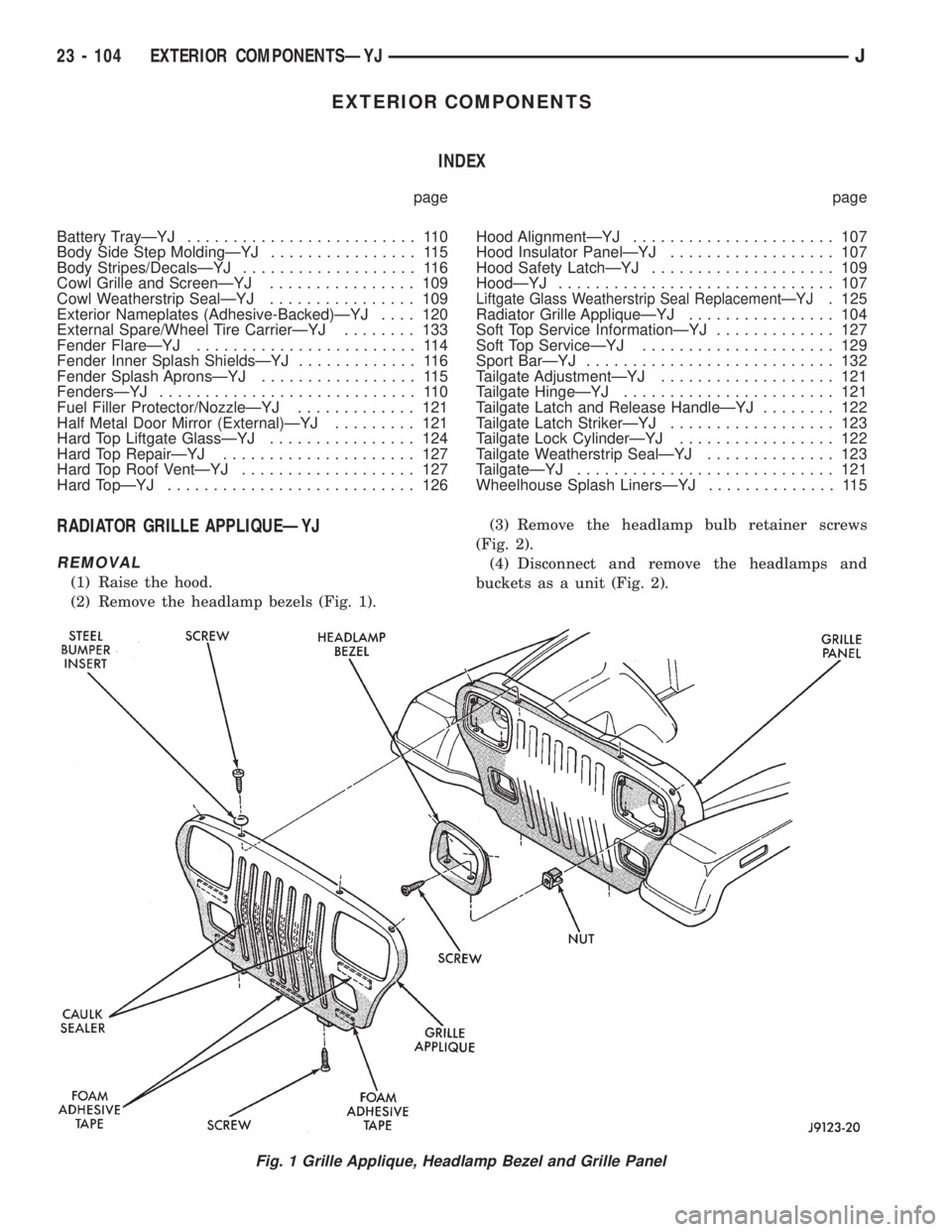
(1) Raise the hood.
(2) Remove the headlamp bezels (Fig. 1).(3) Remove the headlamp bulb retainer screws
(Fig. 2).
(4) Disconnect and remove the headlamps and
buckets as a unit (Fig. 2).
Fig. 1 Grille Applique, Headlamp Bezel and Grille Panel
23 - 104 EXTERIOR COMPONENTSÐYJJ
Page 2023 of 2158
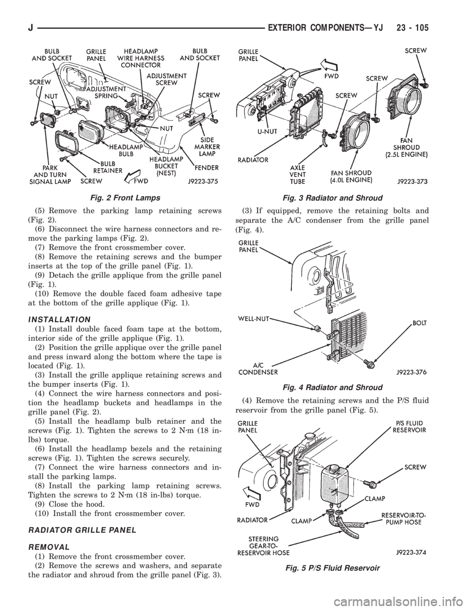
(5) Remove the parking lamp retaining screws
(Fig. 2).
(6) Disconnect the wire harness connectors and re-
move the parking lamps (Fig. 2).
(7) Remove the front crossmember cover.
(8) Remove the retaining screws and the bumper
inserts at the top of the grille panel (Fig. 1).
(9) Detach the grille applique from the grille panel
(Fig. 1).
(10) Remove the double faced foam adhesive tape
at the bottom of the grille applique (Fig. 1).
INSTALLATION
(1) Install double faced foam tape at the bottom,
interior side of the grille applique (Fig. 1).
(2) Position the grille applique over the grille panel
and press inward along the bottom where the tape is
located (Fig. 1).
(3) Install the grille applique retaining screws and
the bumper inserts (Fig. 1).
(4) Connect the wire harness connectors and posi-
tion the headlamp buckets and headlamps in the
grille panel (Fig. 2).
(5) Install the headlamp bulb retainer and the
screws (Fig. 1). Tighten the screws to 2 Nzm (18 in-
lbs) torque.
(6) Install the headlamp bezels and the retaining
screws (Fig. 1). Tighten the screws securely.
(7) Connect the wire harness connectors and in-
stall the parking lamps.
(8) Install the parking lamp retaining screws.
Tighten the screws to 2 Nzm (18 in-lbs) torque.
(9) Close the hood.
(10) Install the front crossmember cover.
RADIATOR GRILLE PANEL
REMOVAL
(1) Remove the front crossmember cover.
(2) Remove the screws and washers, and separate
the radiator and shroud from the grille panel (Fig. 3).(3) If equipped, remove the retaining bolts and
separate the A/C condenser from the grille panel
(Fig. 4).
(4) Remove the retaining screws and the P/S fluid
reservoir from the grille panel (Fig. 5).
Fig. 2 Front LampsFig. 3 Radiator and Shroud
Fig. 4 Radiator and Shroud
Fig. 5 P/S Fluid Reservoir
JEXTERIOR COMPONENTSÐYJ 23 - 105
Page 2024 of 2158
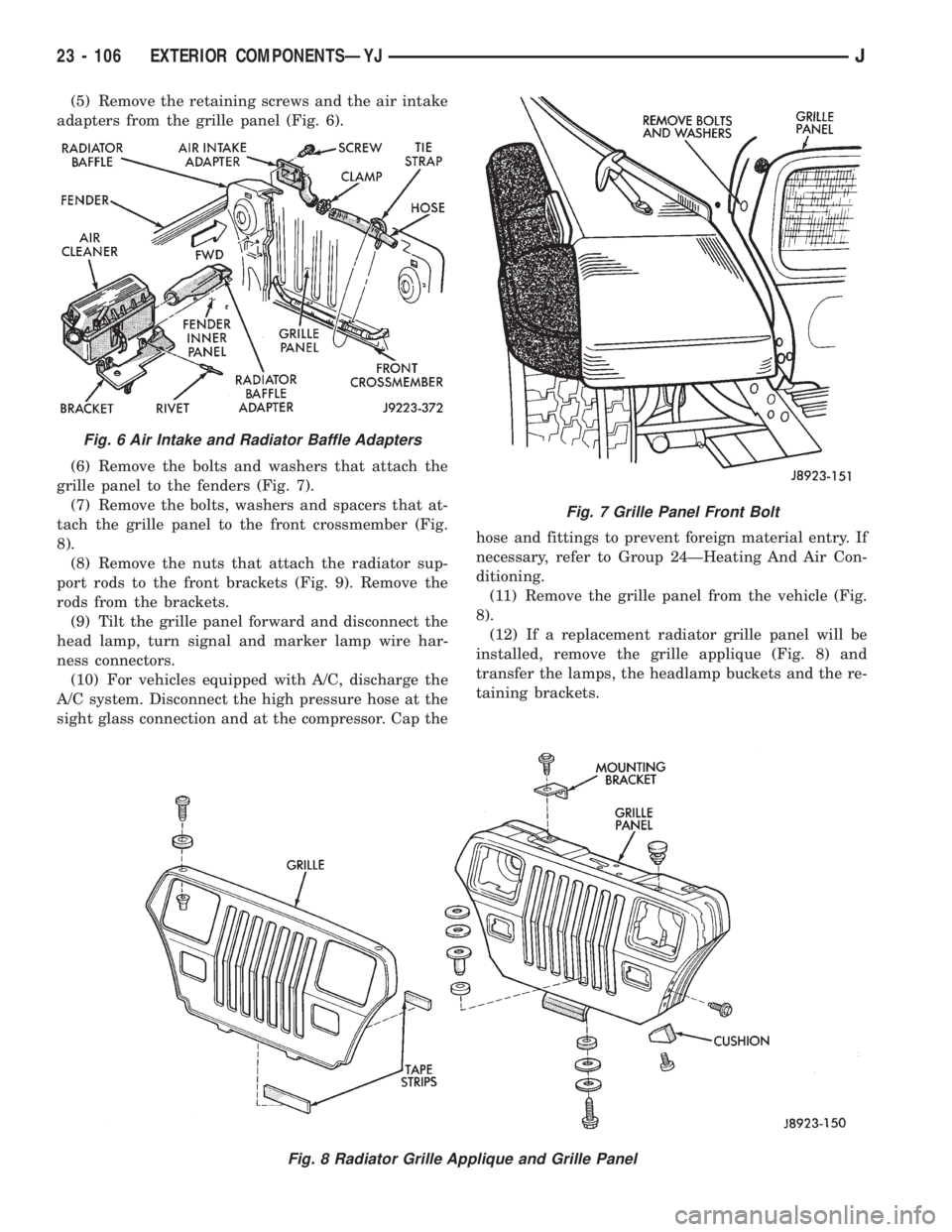
(5) Remove the retaining screws and the air intake
adapters from the grille panel (Fig. 6).
(6) Remove the bolts and washers that attach the
grille panel to the fenders (Fig. 7).
(7) Remove the bolts, washers and spacers that at-
tach the grille panel to the front crossmember (Fig.
8).
(8) Remove the nuts that attach the radiator sup-
port rods to the front brackets (Fig. 9). Remove the
rods from the brackets.
(9) Tilt the grille panel forward and disconnect the
head lamp, turn signal and marker lamp wire har-
ness connectors.
(10) For vehicles equipped with A/C, discharge the
A/C system. Disconnect the high pressure hose at the
sight glass connection and at the compressor. Cap thehose and fittings to prevent foreign material entry. If
necessary, refer to Group 24ÐHeating And Air Con-
ditioning.
(11) Remove the grille panel from the vehicle (Fig.
8).
(12) If a replacement radiator grille panel will be
installed, remove the grille applique (Fig. 8) and
transfer the lamps, the headlamp buckets and the re-
taining brackets.
Fig. 7 Grille Panel Front Bolt
Fig. 8 Radiator Grille Applique and Grille Panel
Fig. 6 Air Intake and Radiator Baffle Adapters
23 - 106 EXTERIOR COMPONENTSÐYJJ