JEEP XJ 1995 Service And Repair Manual
Manufacturer: JEEP, Model Year: 1995, Model line: XJ, Model: JEEP XJ 1995Pages: 2158, PDF Size: 81.9 MB
Page 1151 of 2158
Page 1152 of 2158
Page 1153 of 2158

Page 1154 of 2158
INSTRUMENT CLUSTER
INSTRUMENT CLUSTER
The instrument cluster contains the gauges and
warning lamps. All gauges have magnetic move-
ments.
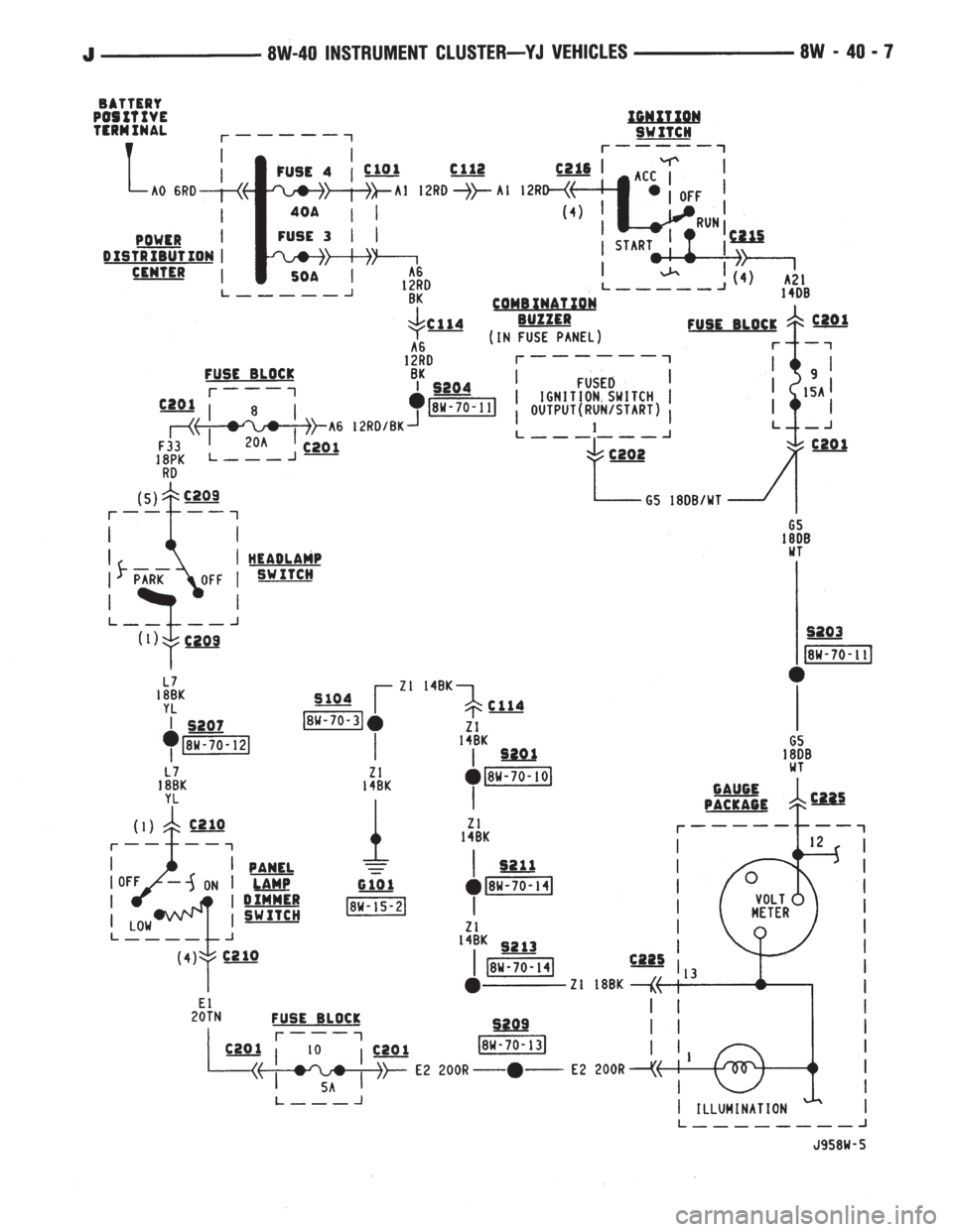
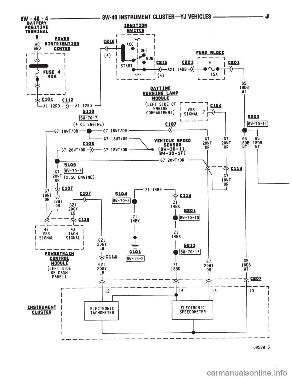
When the ignition switch is in either the START or
RUN position, circuit A1 from fuse 4 in the Power
Distribution Center (PDC) connects to circuit A21.
Circuit A21 powers fuse 9 in the fuse block. Fuse 9
powers circuit G5. One branch of circuit G5 connects
directly to the combination buzzer. The other branch
of circuit G5 splices to power the gauges, speedome-
ter, tachometer, voltmeter, indicator lamps, and
warning lamps in the instrument cluster.
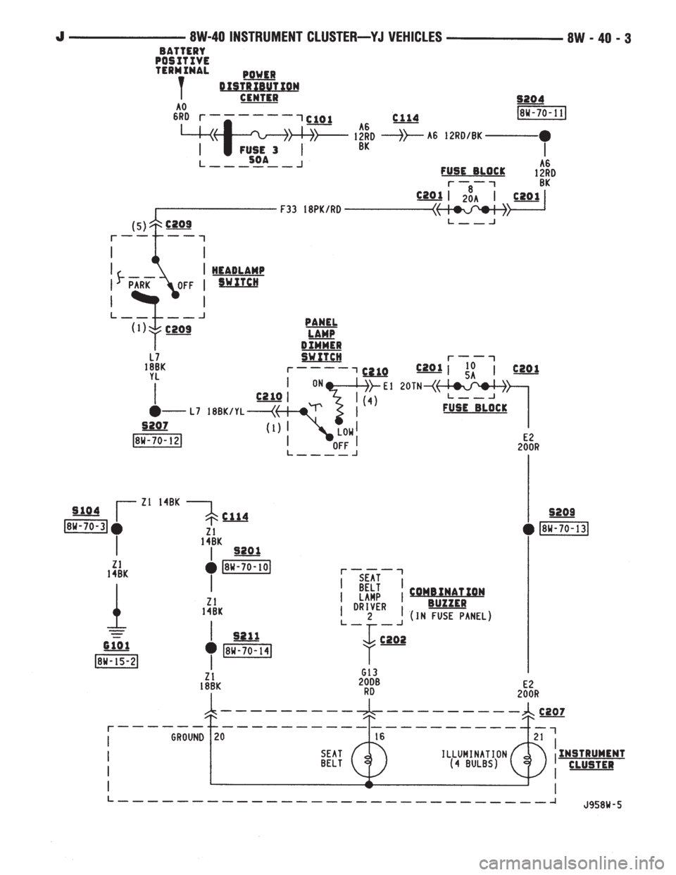
When the parking lamps or headlamps are ON, the
headlamp switch connects circuit F33 to circuit L7.
Circuit L7 splices to the dimmer switch. Circuit E1
from the dimmer switch powers fuse 10 in the fuse
block when the parking lamps or headlamps are ON.
Circuit E2 from fuse 10 in the fuse block feeds the
illumination lamps in the instrument cluster.
Circuit Z1 provides ground the instrument cluster
illumination lamps, gauges and warning lamps.
HELPFUL INFORMATION
²Circuit G5 also powers the heated rear window,
A/C compressor clutch relay. On Canadian vehicles,
circuit G5 powers the Daytime Running Lamps
(DRL) module.
²Circuit F33 originates at fuse 8 in the fuse block.
Circuit A6 from fuse 3 in the PDC powers fuse 8 in
the fuse block.
ENGINE COOLANT TEMPERATURE GAUGE
Circuit G20 connects the engine coolant tempera-
ture gauge to the engine coolant temperature sensor.
The sensor is a variable resistor and case grounded
to the engine. Circuit G5 connects to the instrument
cluster and supplies voltage for the gauge.
The gauge uses two coils. The first coil has fixed
current flowing through it to maintain magnetic field
strength. Circuit Z1 provides ground for the fixed
current coil. The current level passing through the
second coil is controlled by the variable resistor in
the engine coolant temperature sender. The changing
current varies the magnetic field in the second coil.
Refer to group 8E, Instrument Panel and Gauges
for gauge operation.
FUEL GAUGE
Circuit G4 connects the fuel level sensor to the fuel
gauge in the instrument cluster. Circuit G5 supplies
voltage to the fuel gauge. The fuel level sensor draws
voltage from circuit G5 through the fuel gauge on cir-
cuit G4.The gauge uses two coils. The first coil has fixed
current flowing through it to maintain magnetic field
strength. Circuit Z1 provides ground for the fixed
current coil. The current level passing through the
second coil is controlled by the variable resistor in
the fuel level sensor. The changing current varies the
magnetic field in the second coil.
Circuit Z2 provides the ground path for the fuel
level sensor.
Refer to group 8E, Instrument Panel and Gauges
for gauge operation.
OIL PRESSURE GAUGE
The case grounded oil pressure sending unit is a
variable resistor. The sending unit connects to the oil
pressure gauge on circuit G60.
Circuit G5 connects to the instrument cluster and
supplies battery voltage to the oil pressure gauge.
The gauge uses two coils. The first coil has fixed cur-
rent flowing through it to maintain magnetic field
strength. Circuit Z1 provides ground for the fixed
current coil. The current level passing through the
second coil is controlled by the variable resistor in
the oil pressure sending unit. The changing current
varies the magnetic field in the second coil.
Refer to group 8E, Instrument Panel and Gauges
for gauge operation.
TACHOMETER
The Powertrain Control Module (PCM) provides
the tachometer signal to the electronic tachometer on
circuit G21. Circuit G21 originates at cavity 43 of the
PCM. Circuit Z1 provides ground for the tachometer's
internal logic circuits.
SPEEDOMETER
The electronic speedometer and odometer receive a
signal from the vehicle speed sensor on circuit G7.
Circuit G5 connects to the instrument cluster and
supplies battery voltage to the speedometer. Circuit
Z1 provides ground for the speedometer internal logic
circuits.
Circuit G7 splices to connect to the Powertrain
Control Module (PCM) and if equipped, the Daytime
Running Lamps (DRL) module.
FOUR-WHEEL DRIVE (4WD) INDICATOR LAMP
When the 4WD switch closes, circuit Z1 provides
ground for the 4WD indicator lamp in the instrument
panel. Circuit G5 connects to the instrument cluster
and supplies battery voltage to the 4WD indicator
lamp. Circuit G1 connects the indicator lamp to the
4WD switch.
J8W-40 INSTRUMENT CLUSTERÐYJ VEHICLES 8W - 40 - 1
Page 1155 of 2158
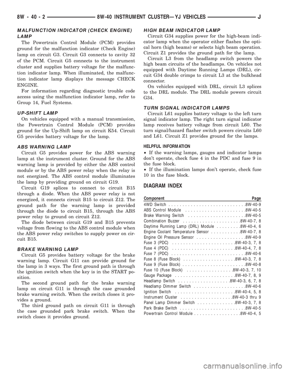
MALFUNCTION INDICATOR (CHECK ENGINE)
LAMP
The Powertrain Control Module (PCM) provides
ground for the malfunction indicator (Check Engine)
lamp on circuit G3. Circuit G3 connects to cavity 32
of the PCM. Circuit G5 connects to the instrument
cluster and supplies battery voltage for the malfunc-
tion indicator lamp. When illuminated, the malfunc-
tion indicator lamp displays the message CHECK
ENGINE.
For information regarding diagnostic trouble code
access using the malfunction indicator lamp, refer to
Group 14, Fuel Systems.
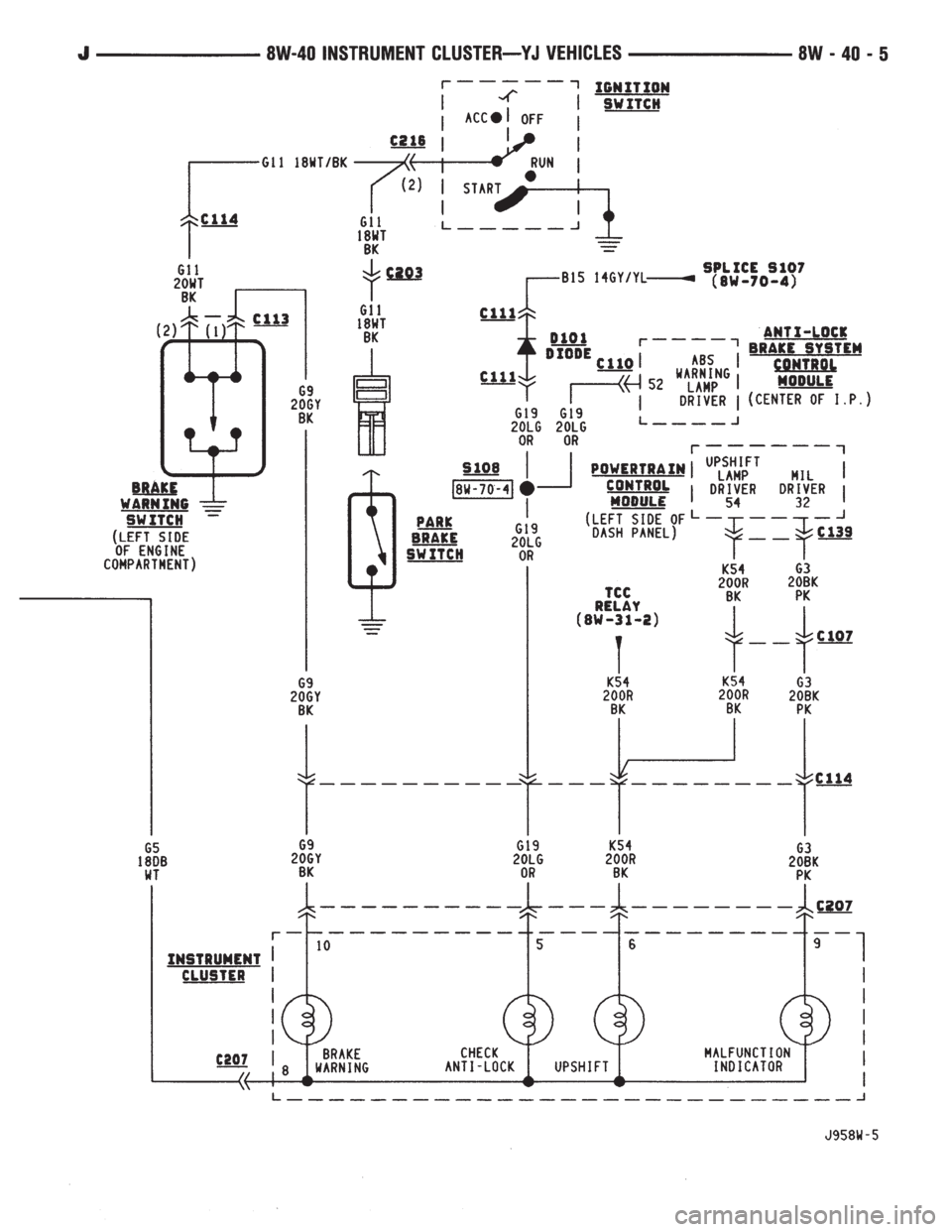
UP-SHIFT LAMP
On vehicles equipped with a manual transmission,
the Powertrain Control Module (PCM) provides
ground for the Up-Shift lamp on circuit K54. Circuit
G5 provides battery voltage for the lamp.
ABS WARNING LAMP
Circuit G5 provides power for the ABS warning
lamp at the instrument cluster. Ground for the ABS
warning lamp is provided by either the ABS control
module or by the ABS power relay when the relay is
not energized. The ABS control module illuminates
the lamp by providing ground on circuit G19.
Circuit G19 splices to connect to circuit B15
through a diode. When the ABS power relay is not
energized, it connects circuit B15 to circuit Z12. The
ground path for the warning lamp is provided
through the diode to circuit B15, through the ABS
power relay to ground on circuit Z12.
The diode between circuit G19 and B15 prevents
voltage from flowing to the ABS control module when
the ABS power relay switches to supply power on cir-
cuit B15.
BRAKE WARNING LAMP
Circuit G5 provides battery voltage for the brake
warning lamp. Circuit G11 can provide ground for
the lamp in 3 ways. The first ground path is through
the ignition switch when the key is in the START po-
sition.
The second ground path for the brake warning
lamp on circuit G11 is through the case grounded
brake warning switch. When the switch closes it pro-
vides a ground.
The third ground path on circuit G11 is through
the case grounded park brake switch. When the
switch closes it provides ground.
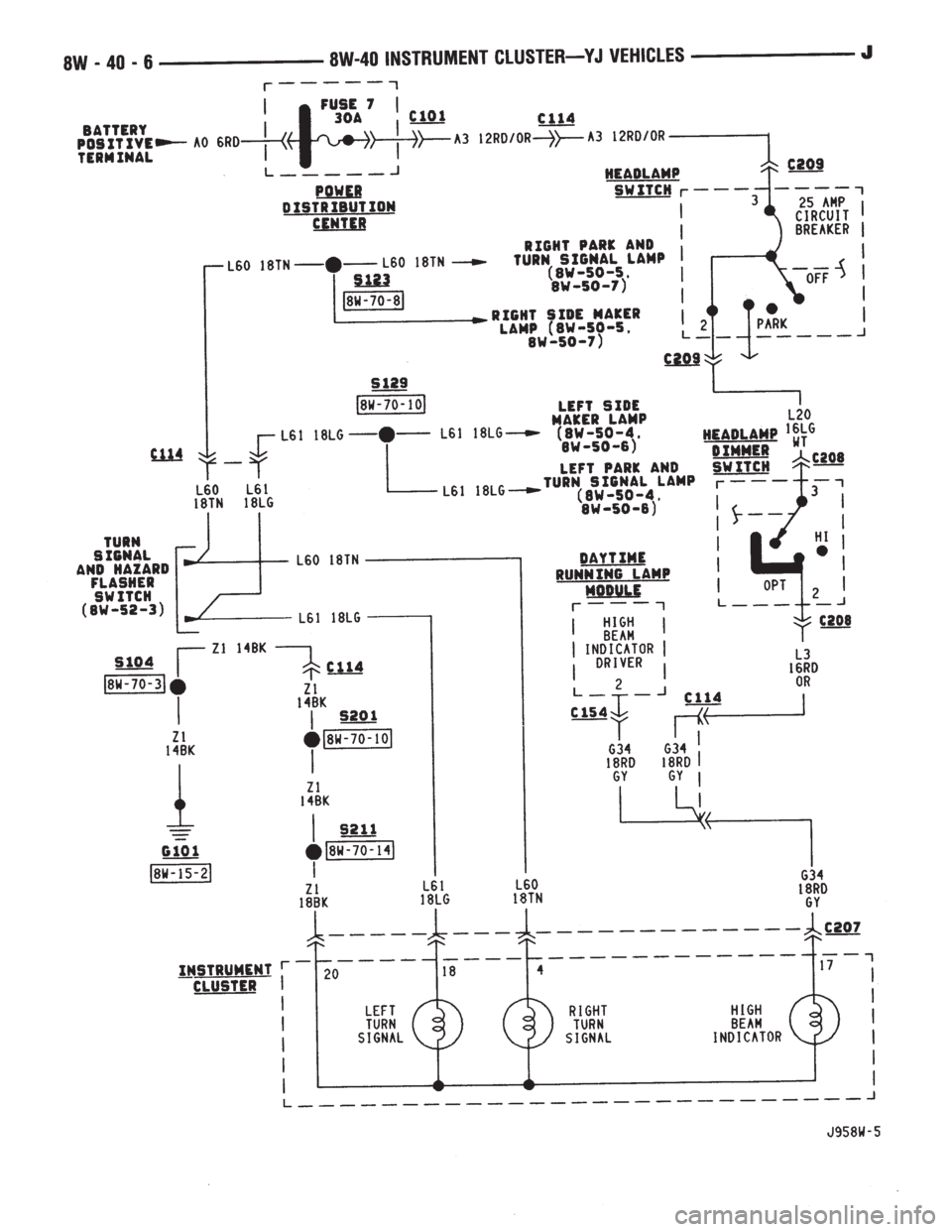
HIGH BEAM INDICATOR LAMP
Circuit G34 supplies power for the high-beam indi-
cator lamp when the operator either flashes the opti-
cal horn (high beams) or selects high beam operation.
Circuit Z1 provides the ground path for the lamp.
Circuit L3 from the headlamp switch powers the
high beam circuits of the headlamps. On vehicles not
equipped with Daytime Running Lamps (DRL), cir-
cuit G34 double crimps to circuit L3 at the bulkhead
connector.
On vehicles equipped with DRL, circuit L3 splices
to the DRL module. The DRL module powers circuit
G34.
TURN SIGNAL INDICATOR LAMPS
Circuit L61 supplies battery voltage to the left turn
signal indicator lamp. The right turn signal indicator
lamp receives battery voltage from circuit L60. The
turn signal/hazard flasher switch powers circuits L60
and L61. Circuit Z1 provides ground for the lamps.
HELPFUL INFORMATION
²If the warning lamps, gauges and indicator lamps
don't operate, check fuse 4 in the PDC and fuse 9 in
the fuse block.
²If the illumination lamps don't operate, check fuse
10 in the fuse block.
DIAGRAM INDEX
Component Page
4WD Switch............................8W-40-9
ABS Control Module......................8W-40-5
Brake Warning Switch.....................8W-40-5
Combination Buzzer.....................8W-40-7, 8
Daytime Running Lamp (DRL) Module.........8W-40-4, 6
Engine Coolant Temperature Sensor...........8W-40-7, 8
Engine Oil Pressure Sensor..................8W-40-9
Fuse 3 (PDC).......................8W-40-3, 7, 8
Fuse 4 (PDC).......................8W-40-4, 7, 8
Fuse 7 (PDC)...........................8W-40-6
Fuse 8 (Fuse Block)...................8W-40-3, 7, 8
Fuse 9 (Fuse Block).......................8W-40-8
Fuse 10 (Fuse Block).................8W-40-3, 7, 10
Gauge Package......................8W-40-7, 8, 9
Headlamp Switch...................8W-40-3, 6, 7, 8
Headlamp Dimmer Switch...................8W-40-6
Ignition Switch......................8W-40-4, 5, 8
Instrument Cluster...................8W-40-3 thru 9
Panel Lamp Dimmer Switch..............8W-40-3, 7, 8
Park Brake Switch........................8W-40-5
Powertrain Control Module.................8W-40-4, 5
8W - 40 - 2 8W-40 INSTRUMENT CLUSTERÐYJ VEHICLESJ
Page 1156 of 2158
Page 1157 of 2158
Page 1158 of 2158
Page 1159 of 2158
Page 1160 of 2158
