JEEP XJ 1995 Service And Repair Manual
Manufacturer: JEEP, Model Year: 1995, Model line: XJ, Model: JEEP XJ 1995Pages: 2158, PDF Size: 81.9 MB
Page 1161 of 2158
Page 1162 of 2158
Page 1163 of 2158

Page 1164 of 2158
HORN/CIGAR LIGHTER
HORN
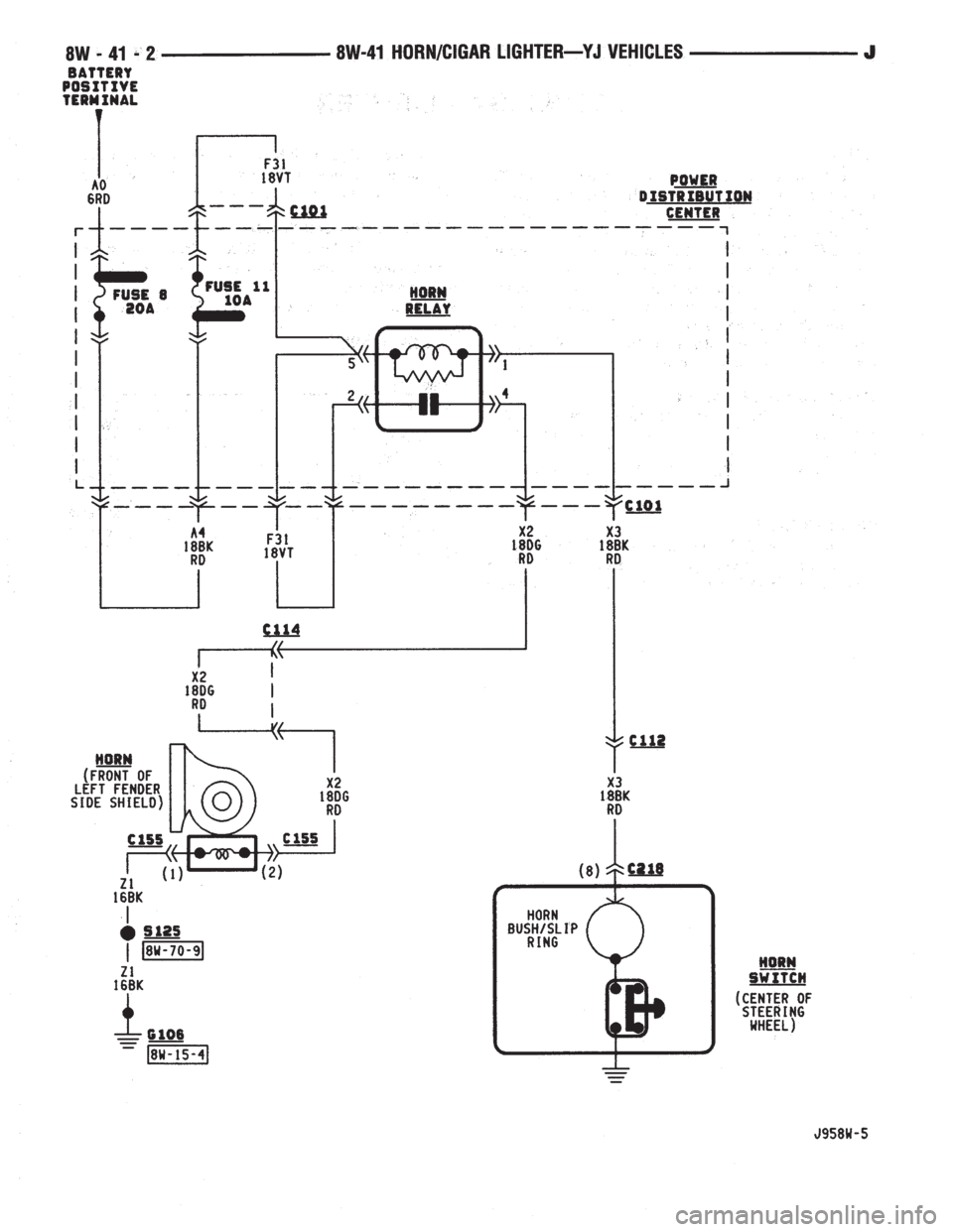
The horn system uses a switch and horn relay. The
horn switch is in the center of the steering wheel.
Circuit A4 from fuse 8 in the Power Distribution
Center (PDC) feeds circuit F31 through fuse 15 in
the PDC. Circuit F31 is HOT at all times and powers
the coil and contact sides of the horn relay.
When the case grounded horn switch is pressed,
circuit X3 provides ground for the coil side of the re-
lay and the contacts close. When the contacts close,
circuit X2 supplies voltage to the horn. Circuit Z1
provides ground for the horn.
HELPFUL INFORMATION
²The horn switch is grounded to the steering wheel.
²Circuit F31 is double crimped at the coil side of
the horn relay.
²Check fuse 8 in the PDC and fuse 15 in the fuse
block.
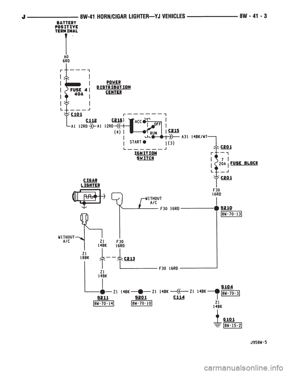
CIGAR LIGHTER
In the ACCESSORY or RUN position, the ignition
switch supplies voltage to fuse 7 in the fuse block on
circuit A31. Fuse 7 feeds circuit F30 which connects
to the cigar lighter. When the lighter is depressed,
the contacts inside of the lighter element close and
voltage flows to ground on circuit Z1.
HELPFUL INFORMATION
²In the ACCESSORY or RUN position, the ignition
switch connects circuit A1 from fuse 4 in the PDC
with circuit A31.
²Circuit F30 also powers the radio and radio relay.
DIAGRAM INDEX
Component Page
Cigar Lighter...........................8W-41-3
Fuse 4 (PDC)...........................8W-41-3
Fuse 8 (PDC)...........................8W-41-2
Fuse 11 (PDC)..........................8W-41-2
Fuse 7 (Fuse Block).......................8W-41-3
Horn.................................8W-41-2
Horn Relay.............................8W-41-2
Horn Switch............................8W-41-2
Ignition Switch..........................8W-41-3
J8W-41 HORN/CIGAR LIGHTERÐYJ VEHICLES 8W - 41 - 1
Page 1165 of 2158
Page 1166 of 2158
Page 1167 of 2158

Page 1168 of 2158
AIR CONDITIONING/HEATER
CONTENTS
page page
HEATER AND AIR CONDITIONING........... 2 HEATERSYSTEM......................... 1
GENERAL INFORMATION
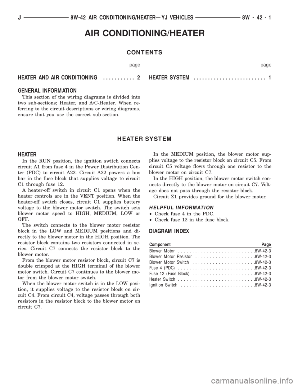
This section of the wiring diagrams is divided into
two sub-sections; Heater, and A/C-Heater. When re-
ferring to the circuit descriptions or wiring diagrams,
ensure that you use the correct sub-section.
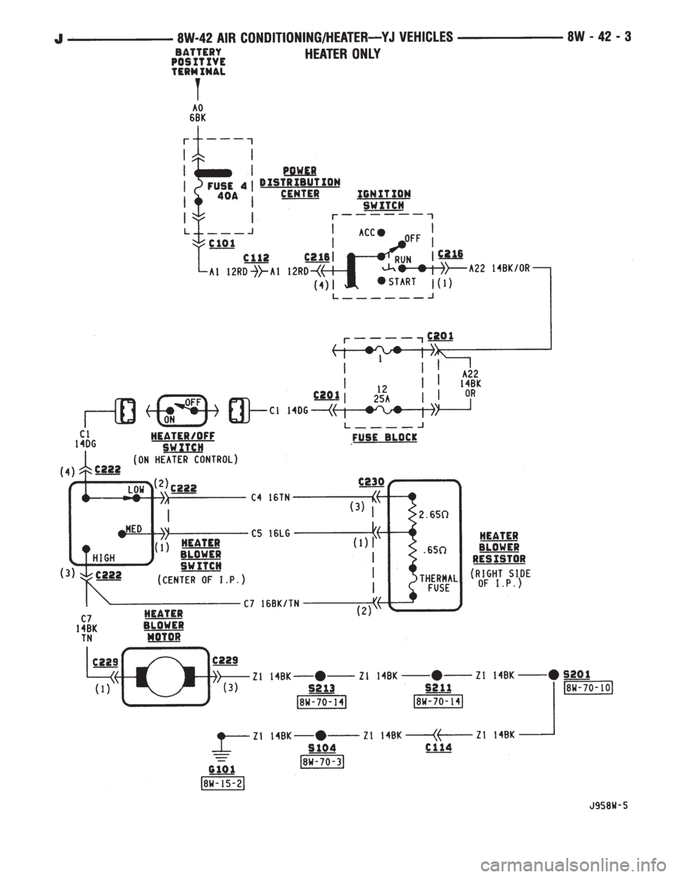
HEATER SYSTEM
HEATER
In the RUN position, the ignition switch connects
circuit A1 from fuse 4 in the Power Distribution Cen-
ter (PDC) to circuit A22. Circuit A22 powers a bus
bar in the fuse block that supplies voltage to circuit
C1 through fuse 12.
A heater-off switch in circuit C1 opens when the
heater controls are in the VENT position. When the
heater-off switch closes, circuit C1 supplies battery
voltage to the blower motor switch. The switch sets
blower motor speed to HIGH, MEDIUM, LOW or
OFF.
The switch connects to the blower motor resistor
block in the LOW and MEDIUM positions and di-
rectly to the blower motor in the HIGH position. The
resistor block contains two resistors connected in se-
ries. Circuit C7 connects the resistor block to the
blower motor.
From the blower motor resistor block, circuit C7 is
double crimped at the HIGH terminal of the blower
motor switch. Circuit C7 continues to the blower mo-
tor from the blower motor switch.
When the blower motor switch is in the LOW posi-
tion, it supplies voltage to the resistor block on cir-
cuit C4. From circuit C4, voltage passes through both
resistors in the resistor block to the blower motor on
circuit C7.In the MEDIUM position, the blower motor sup-
plies voltage to the resistor block on circuit C5. From
circuit C5 voltage flows through one resistor to the
blower motor on circuit C7.
In the HIGH position, the blower motor switch con-
nects directly to the blower motor on circuit C7. Volt-
age does not pass through the resistor block.
Circuit Z1 provides ground for the blower motor.
HELPFUL INFORMATION
²Check fuse 4 in the PDC.
²Check fuse 12 in the fuse block.
DIAGRAM INDEX
Component Page
Blower Motor...........................8W-42-3
Blower Motor Resistor.....................8W-42-3
Blower Motor Switch......................8W-42-3
Fuse 4 (PDC)...........................8W-42-3
Fuse 12 (Fuse Block)......................8W-42-3
Heater Switch...........................8W-42-3
Ignition Switch..........................8W-42-3
J8W-42 AIR CONDITIONING/HEATERÐYJ VEHICLES 8W - 42 - 1
Page 1169 of 2158
AIR CONDITIONING AND HEATER
GENERAL INFORMATION
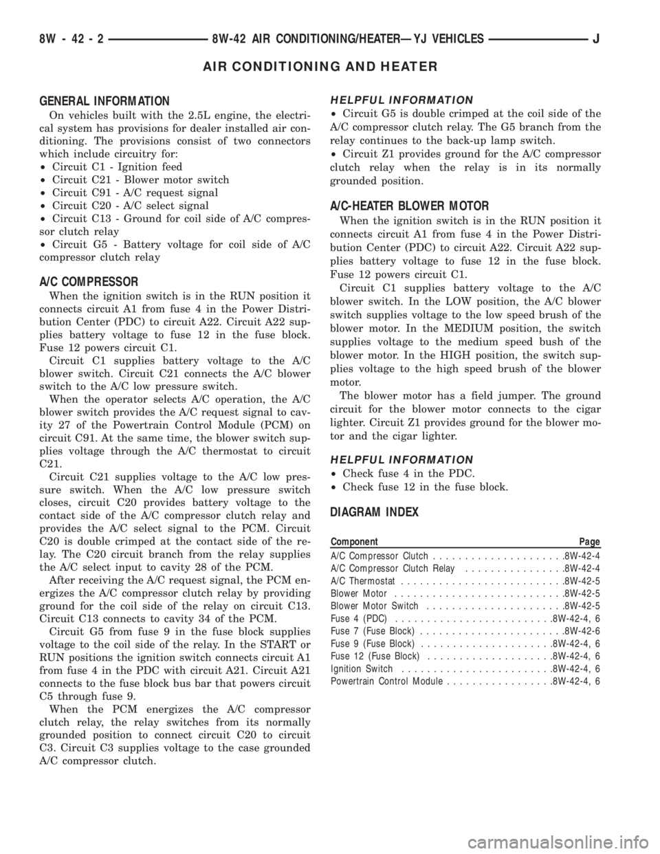
On vehicles built with the 2.5L engine, the electri-
cal system has provisions for dealer installed air con-
ditioning. The provisions consist of two connectors
which include circuitry for:
²Circuit C1 - Ignition feed
²Circuit C21 - Blower motor switch
²Circuit C91 - A/C request signal
²Circuit C20 - A/C select signal
²Circuit C13 - Ground for coil side of A/C compres-
sor clutch relay
²Circuit G5 - Battery voltage for coil side of A/C
compressor clutch relay
A/C COMPRESSOR
When the ignition switch is in the RUN position it
connects circuit A1 from fuse 4 in the Power Distri-
bution Center (PDC) to circuit A22. Circuit A22 sup-
plies battery voltage to fuse 12 in the fuse block.
Fuse 12 powers circuit C1.
Circuit C1 supplies battery voltage to the A/C
blower switch. Circuit C21 connects the A/C blower
switch to the A/C low pressure switch.
When the operator selects A/C operation, the A/C
blower switch provides the A/C request signal to cav-
ity 27 of the Powertrain Control Module (PCM) on
circuit C91. At the same time, the blower switch sup-
plies voltage through the A/C thermostat to circuit
C21.
Circuit C21 supplies voltage to the A/C low pres-
sure switch. When the A/C low pressure switch
closes, circuit C20 provides battery voltage to the
contact side of the A/C compressor clutch relay and
provides the A/C select signal to the PCM. Circuit
C20 is double crimped at the contact side of the re-
lay. The C20 circuit branch from the relay supplies
the A/C select input to cavity 28 of the PCM.
After receiving the A/C request signal, the PCM en-
ergizes the A/C compressor clutch relay by providing
ground for the coil side of the relay on circuit C13.
Circuit C13 connects to cavity 34 of the PCM.
Circuit G5 from fuse 9 in the fuse block supplies
voltage to the coil side of the relay. In the START or
RUN positions the ignition switch connects circuit A1
from fuse 4 in the PDC with circuit A21. Circuit A21
connects to the fuse block bus bar that powers circuit
C5 through fuse 9.
When the PCM energizes the A/C compressor
clutch relay, the relay switches from its normally
grounded position to connect circuit C20 to circuit
C3. Circuit C3 supplies voltage to the case grounded
A/C compressor clutch.
HELPFUL INFORMATION
²Circuit G5 is double crimped at the coil side of the
A/C compressor clutch relay. The G5 branch from the
relay continues to the back-up lamp switch.
²Circuit Z1 provides ground for the A/C compressor
clutch relay when the relay is in its normally
grounded position.
A/C-HEATER BLOWER MOTOR
When the ignition switch is in the RUN position it
connects circuit A1 from fuse 4 in the Power Distri-
bution Center (PDC) to circuit A22. Circuit A22 sup-
plies battery voltage to fuse 12 in the fuse block.
Fuse 12 powers circuit C1.
Circuit C1 supplies battery voltage to the A/C
blower switch. In the LOW position, the A/C blower
switch supplies voltage to the low speed brush of the
blower motor. In the MEDIUM position, the switch
supplies voltage to the medium speed bush of the
blower motor. In the HIGH position, the switch sup-
plies voltage to the high speed brush of the blower
motor.
The blower motor has a field jumper. The ground
circuit for the blower motor connects to the cigar
lighter. Circuit Z1 provides ground for the blower mo-
tor and the cigar lighter.
HELPFUL INFORMATION
²Check fuse 4 in the PDC.
²Check fuse 12 in the fuse block.
DIAGRAM INDEX
Component Page
A/C Compressor Clutch.....................8W-42-4
A/C Compressor Clutch Relay................8W-42-4
A/C Thermostat..........................8W-42-5
Blower Motor...........................8W-42-5
Blower Motor Switch......................8W-42-5
Fuse 4 (PDC).........................8W-42-4, 6
Fuse 7 (Fuse Block).......................8W-42-6
Fuse 9 (Fuse Block).....................8W-42-4, 6
Fuse 12 (Fuse Block)....................8W-42-4, 6
Ignition Switch........................8W-42-4, 6
Powertrain Control Module.................8W-42-4, 6
8W - 42 - 2 8W-42 AIR CONDITIONING/HEATERÐYJ VEHICLESJ
Page 1170 of 2158
