JEEP XJ 1995 Service And Repair Manual
Manufacturer: JEEP, Model Year: 1995, Model line: XJ, Model: JEEP XJ 1995Pages: 2158, PDF Size: 81.9 MB
Page 1521 of 2158
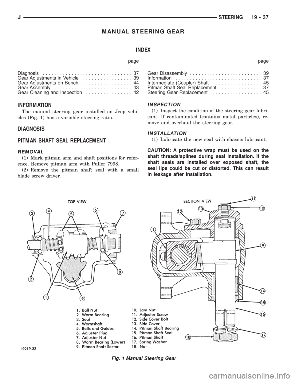
MANUAL STEERING GEAR
INDEX
page page
Diagnosis............................... 37
Gear Adjustments in Vehicle................. 39
Gear Adjustments on Bench................. 44
Gear Assembly........................... 43
Gear Cleaning and Inspection................ 42Gear Disassembly......................... 39
Information.............................. 37
Intermediate (Coupler) Shaft................. 45
Pitman Shaft Seal Replacement.............. 37
Steering Gear Replacement................. 45
INFORMATION
The manual steering gear installed on Jeep vehi-
cles (Fig. 1) has a variable steering ratio.
DIAGNOSIS
PITMAN SHAFT SEAL REPLACEMENT
REMOVAL
(1) Mark pitman arm and shaft positions for refer-
ence. Remove pitman arm with Puller 7998.
(2) Remove the pitman shaft seal with a small
blade screw driver.
INSPECTION
(1) Inspect the condition of the steering gear lubri-
cant. If contaminated (contains metal particles), re-
move and overhaul the steering gear.
INSTALLATION
(1) Lubricate the new seal with chassis lubricant.
CAUTION: A protective wrap must be used on the
shaft threads/splines during seal installation. If the
shaft seals are installed over exposed shaft, the
seal lips could be cut or distorted. This can result
in leakage after installation.
Fig. 1 Manual Steering Gear
JSTEERING 19 - 37
Page 1522 of 2158
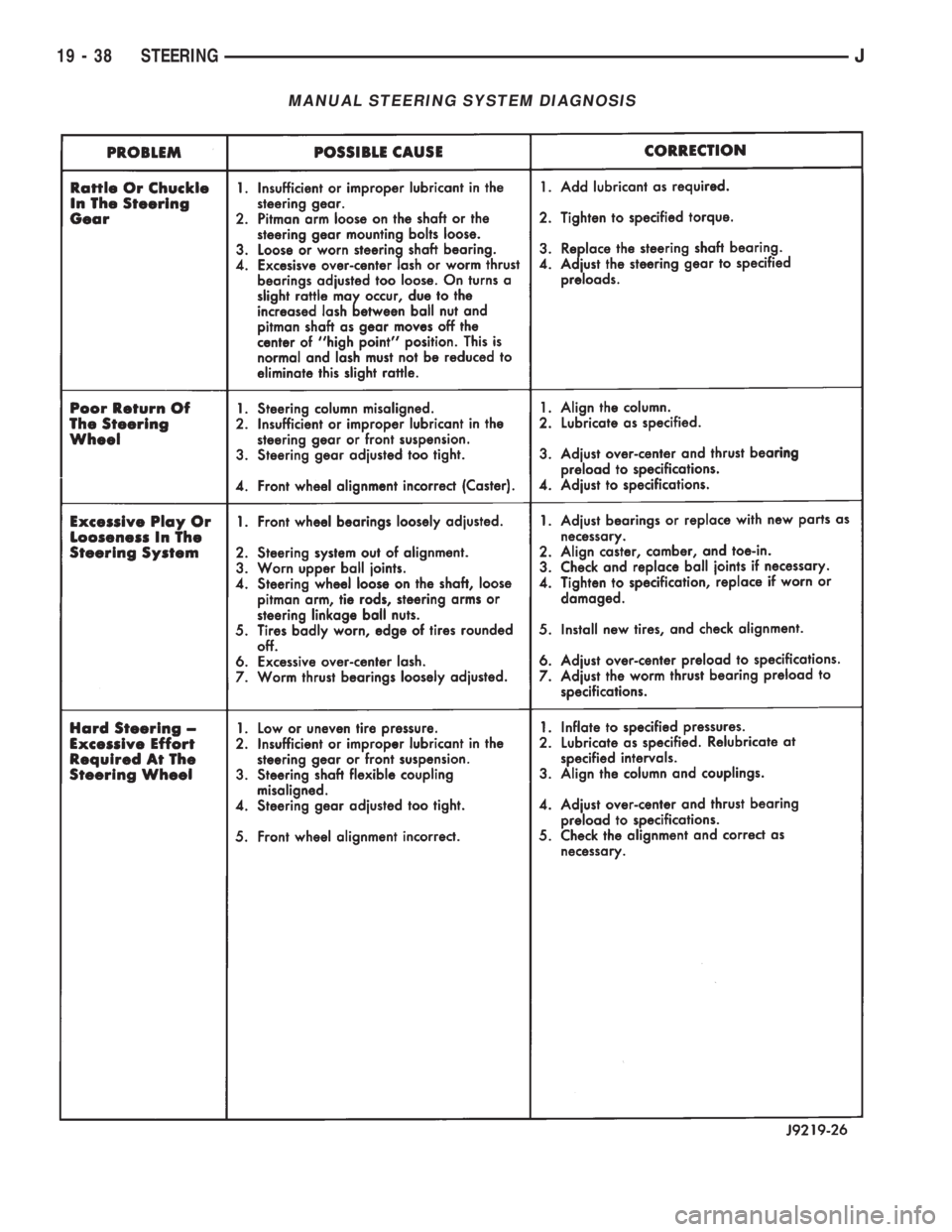
MANUAL STEERING SYSTEM DIAGNOSIS
19 - 38 STEERINGJ
Page 1523 of 2158
(2) Wrap a single layer of plastic tape around the
pitman shaft threads and splines. This will protect
the replacement seals during installation.
(3) Install the seal with a suitable size socket.
(4) Remove the tape from the shaft.
(5) Center the steering gear.
(6) Align and install the pitman arm.
(7) Install the washer and retaining nut on the pit-
man shaft. Tighten the nut to 251 Nzm (185 ft. lbs.)
torque.
GEAR ADJUSTMENTS IN VEHICLE
REMOVE
(1) Raise and support the vehicle.
(2) Mark the pitman shaft and pitman arm for in-
stallation reference. Remove the pitman arm from
the shaft.
(3) Loosen the adjuster lock nut then back the ad-
juster plug off 1/4 turn.
(4) Remove the steering wheel horn pad.
(5) Turn the steering wheel in one direction until
stopped by the gear. Then turn back 1/2 turn.
CAUTION: Do not turn the steering wheel hard
against the internal stops when the linkage is re-
moved. This could result in damage to the recircu-
lating ball guides.
MEASURE
Place a low calibration (50 in. lbs.) torque wrench
and socket on the steering wheel nut. Rotate the
wrench and nut through a 90 degree arc (1/4 turn).
This will measure the worm shaft bearing preload.
ADJUST WORMSHAFT BEARING PRELOAD
TORQUE
(1) Adjust the preload by tightening the adjuster
plug. The preload should be 0.6 to 1 Nzm(5to8in.
lbs.) torque.
Steering column/shaft misalignment or damage will
increase the amount of torque required to rotate the
steering wheel. If the rotating torque is exceptionally
high, inspect the steering column/shaft alignment. If
the alignment is correct, remove the steering gear,
determine the cause of the high preload torque, and
repair as necessary.
(2) Tighten the adjuster locknut to 68 Nzm (50 ft.
lbs.) torque. Measure the preload torque. If neces-
sary, adjust the preload torque again.
ADJUST OVERCENTER DRAG TORQUE
(1) Turn the steering wheel from one stop to the
other and count the total numbers of turns. Turn the
wheel back in reverse direction 1/2 the total number
of turns to center the steering gear.(2) Turn the over center adjusting screw in to re-
move all lash between the ball nut and pitman shaft
sector teeth. Hold the adjustment screw and tighten
the lock nut to 34 Nzm (25 ft. lbs.) torque.
(3) Check the torque at the steering wheel by tak-
ing the highest reading as the wheel is turned
through the center position.
(4) The overcenter drag torque should be 0.5 to 1
Nzm (4 to 10 in. lbs.).
(5) If necessary, loosen the lock nut and adjust the
over center adjuster screw to obtain the proper
torque. Re-tighten the lock nut to the lock nut.
(6) After tightening the locknut, measure the over-
center drag torque again and readjust the torque, if
necessary.
INSTALL
(1) Align the installation reference marks and in-
stall the pitman arm.
(2) Install and tighten the pitman shaft nut and
washer to 251 Nzm (185 ft. lbs.) torque.
(3) Install the horn button.
GEAR DISASSEMBLY
(1) Rotate the wormshaft from stop-to-stop and
count the number of rotations. Rotate the wormshaft
in the reverse direction 1/2 of the total number of ro-
tations to center it and the ball nut.
(2) Remove the pitman shaft adjustment screw
locknut. Remove the cover retaining bolts, cover, and
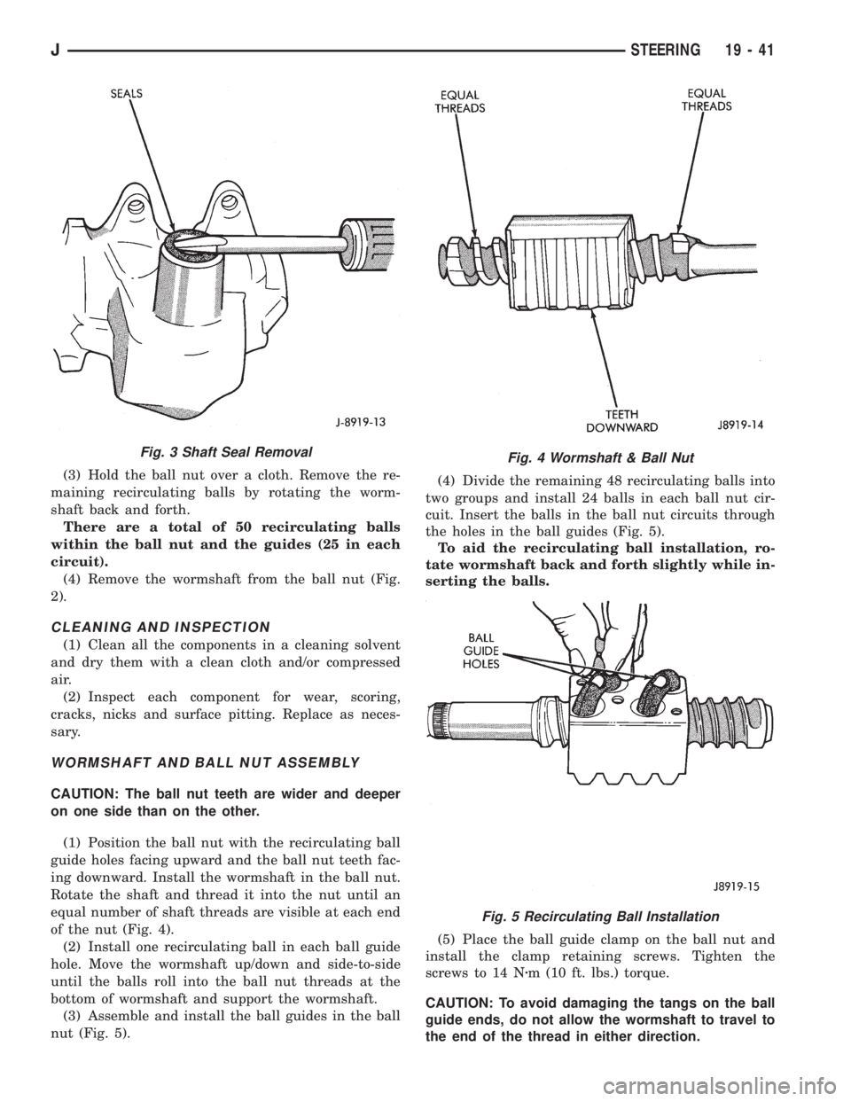
gasket (Fig. 3).
(3) Slide the adjustment screw head (Fig. 3) out of
the pitman shaft T-slot and remove it and the
shim(s).
(4) Retain the shim(s) for end-play measurement
during assembly.
(5) Remove the pitman shaft, the wormshaft bear-
ing preload torque adjustment cap locknut, and the
adjustment cap (Fig. 2).
(6) Remove the wormshaft and the ball nut (Fig.
2).
(7) Remove (pry) the pitman shaft and the worm-
shaft seals from the steering gear housing (Fig. 3).
WORMSHAFT AND BALL NUT DISASSEMBLY
(1) Remove the upper bearing from the wormshaft
(Fig. 2).
CAUTION: Do not allow the ball nut to rotate freely
and travel to either extreme end of the wormshaft.
This could damage the tangs at the ends of the re-
circulating ball guides (Fig. 3).
(2) Remove the recirculating ball guide clamp re-
taining screws, the clamp and the guides (Fig. 2).
Separate the half-guides and place the recirculating
balls aside in a container.
JSTEERING 19 - 39
Page 1524 of 2158
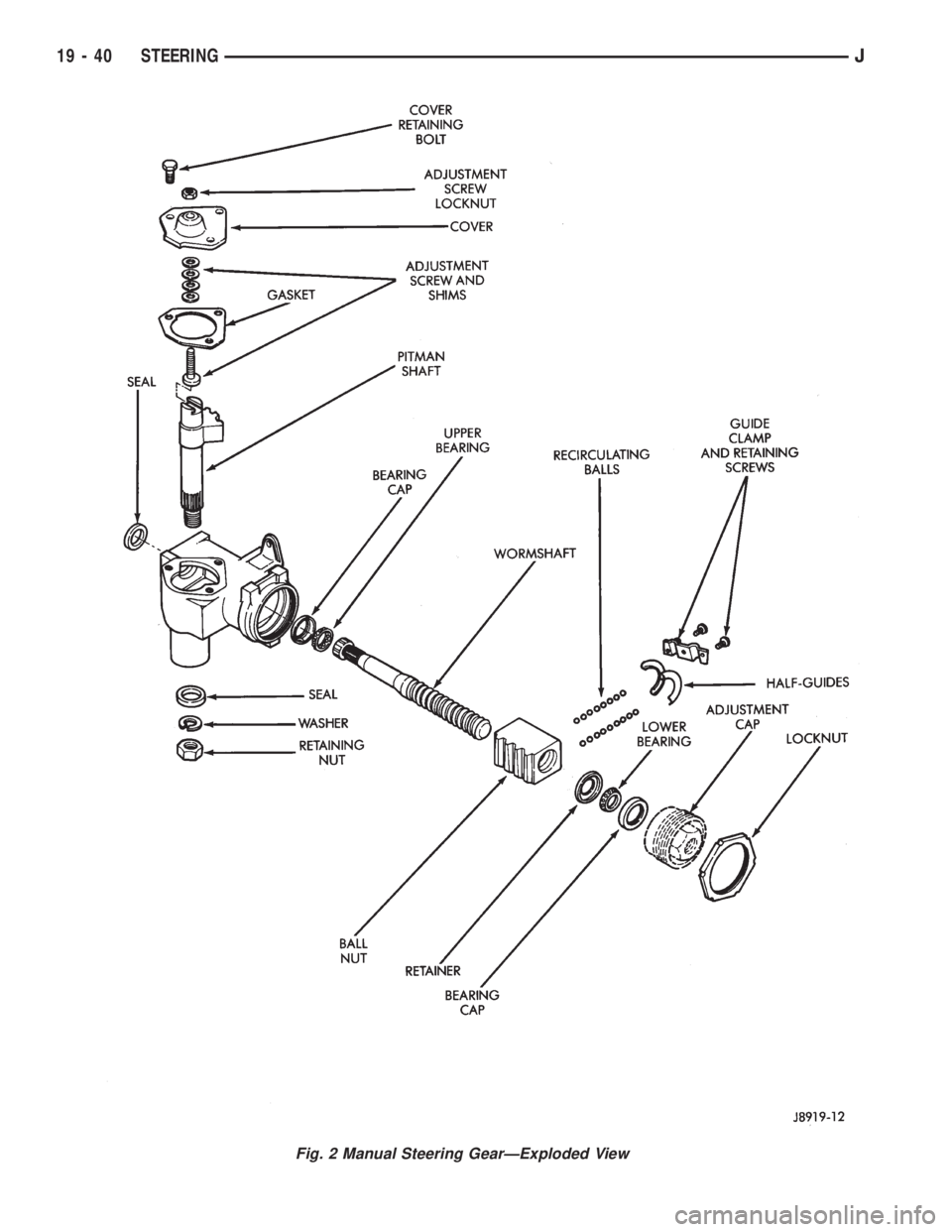
Fig. 2 Manual Steering GearÐExploded View
19 - 40 STEERINGJ
Page 1525 of 2158
(3) Hold the ball nut over a cloth. Remove the re-
maining recirculating balls by rotating the worm-
shaft back and forth.
There are a total of 50 recirculating balls
within the ball nut and the guides (25 in each
circuit).
(4) Remove the wormshaft from the ball nut (Fig.
2).
CLEANING AND INSPECTION
(1) Clean all the components in a cleaning solvent
and dry them with a clean cloth and/or compressed
air.
(2) Inspect each component for wear, scoring,
cracks, nicks and surface pitting. Replace as neces-
sary.
WORMSHAFT AND BALL NUT ASSEMBLY
CAUTION: The ball nut teeth are wider and deeper
on one side than on the other.
(1) Position the ball nut with the recirculating ball
guide holes facing upward and the ball nut teeth fac-
ing downward. Install the wormshaft in the ball nut.
Rotate the shaft and thread it into the nut until an
equal number of shaft threads are visible at each end
of the nut (Fig. 4).
(2) Install one recirculating ball in each ball guide
hole. Move the wormshaft up/down and side-to-side
until the balls roll into the ball nut threads at the
bottom of wormshaft and support the wormshaft.
(3) Assemble and install the ball guides in the ball
nut (Fig. 5).(4) Divide the remaining 48 recirculating balls into
two groups and install 24 balls in each ball nut cir-
cuit. Insert the balls in the ball nut circuits through
the holes in the ball guides (Fig. 5).
To aid the recirculating ball installation, ro-
tate wormshaft back and forth slightly while in-
serting the balls.
(5) Place the ball guide clamp on the ball nut and
install the clamp retaining screws. Tighten the
screws to 14 Nzm (10 ft. lbs.) torque.
CAUTION: To avoid damaging the tangs on the ball
guide ends, do not allow the wormshaft to travel to
the end of the thread in either direction.
Fig. 3 Shaft Seal RemovalFig. 4 Wormshaft & Ball Nut
Fig. 5 Recirculating Ball Installation
JSTEERING 19 - 41
Page 1526 of 2158
(6) Lubricate the wormshaft threads with chassis
lubricant. Rotate the shaft to move it in and out of
the ball nut and distribute the lubricant.
(7) Lubricate the wormshaft upper bearing with
chassis lubricant and install it on the wormshaft.
WORMSHAFT BEARING ADJUSTMENT CAP
DISASSEMBLY
(1) Pry out and remove the wormshaft lower bear-
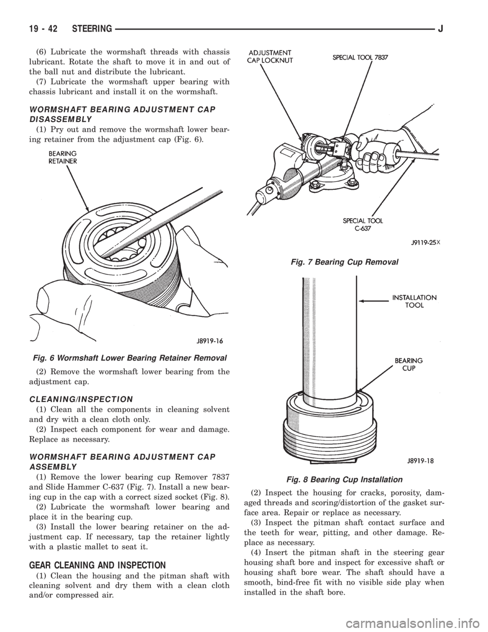
ing retainer from the adjustment cap (Fig. 6).
(2) Remove the wormshaft lower bearing from the
adjustment cap.
CLEANING/INSPECTION
(1) Clean all the components in cleaning solvent
and dry with a clean cloth only.
(2) Inspect each component for wear and damage.
Replace as necessary.
WORMSHAFT BEARING ADJUSTMENT CAP
ASSEMBLY
(1) Remove the lower bearing cup Remover 7837
and Slide Hammer C-637 (Fig. 7). Install a new bear-
ing cup in the cap with a correct sized socket (Fig. 8).
(2) Lubricate the wormshaft lower bearing and
place it in the bearing cup.
(3) Install the lower bearing retainer on the ad-
justment cap. If necessary, tap the retainer lightly
with a plastic mallet to seat it.
GEAR CLEANING AND INSPECTION
(1) Clean the housing and the pitman shaft with
cleaning solvent and dry them with a clean cloth
and/or compressed air.(2) Inspect the housing for cracks, porosity, dam-
aged threads and scoring/distortion of the gasket sur-
face area. Repair or replace as necessary.
(3) Inspect the pitman shaft contact surface and
the teeth for wear, pitting, and other damage. Re-
place as necessary.
(4) Insert the pitman shaft in the steering gear
housing shaft bore and inspect for excessive shaft or
housing shaft bore wear. The shaft should have a
smooth, bind-free fit with no visible side play when
installed in the shaft bore.
Fig. 6 Wormshaft Lower Bearing Retainer Removal
Fig. 7 Bearing Cup Removal
X
Fig. 8 Bearing Cup Installation
19 - 42 STEERINGJ
Page 1527 of 2158
(5) If the shaft fit is loose but it is not visibly
worn, trial fit a replacement pitman shaft in the
housing shaft bore. If the replacement shaft also has
a loose fit, replace the housing. However, if the re-
placement pitman fits properly, replace the original
pitman shaft.
(6) Measure the pitman shaft adjustment screw fit
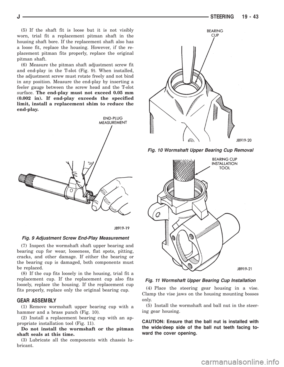
and end-play in the T-slot (Fig. 9). When installed,
the adjustment screw must rotate freely and not bind
in any position. Measure the end-play by inserting a
feeler gauge between the screw head and the T-slot
surface.The end-play must not exceed 0.05 mm
(0.002 in). If end-play exceeds the specified
limit, install a replacement shim to reduce the
end-play.
(7) Inspect the wormshaft shaft upper bearing and
bearing cup for wear, looseness, flat spots, pitting,
cracks, and other damage. If either the bearing or
the bearing cup is damaged, both components must
be replaced.
(8) If the cup fits loosely in the housing, trial fit a
replacement cup. If the replacement cup also fits
loosely, replace the housing. If the replacement cup
fits properly, replace only the original bearing cup.
GEAR ASSEMBLY
(1) Remove wormshaft upper bearing cup with a
hammer and a brass punch (Fig. 10).
(2) Install a replacement bearing cup with an ap-
propriate installation tool (Fig. 11).
Do not install the wormshaft or the pitman
shaft seals at this time.
(3) Lubricate all the components with chassis lu-
bricant.(4) Place the steering gear housing in a vise.
Clamp the vise jaws on the housing mounting bosses
only.
(5) Install the wormshaft and ball nut in the steer-
ing gear housing.
CAUTION: Ensure that the ball nut is installed with
the wide/deep side of the ball nut teeth facing to-
ward the cover opening.
Fig. 9 Adjustment Screw End-Play Measurement
Fig. 10 Wormshaft Upper Bearing Cup Removal
Fig. 11 Wormshaft Upper Bearing Cup Installation
JSTEERING 19 - 43
Page 1528 of 2158
(6) Install the wormshaft bearing adjustment cap
in the housing and tighten it only enough to remove
the wormshaft end-play.
(7) Install the locknut on the wormshaft bearing
adjustment cap but do not tighten it at this time.
(8) Pack the steering gear housing with as much
chassis lubricant as possible.
Rotate the wormshaft in one direction until
the ball nut ceases. Pack the end of the housing
full of lubricant, rotate the shaft in the opposite
direction and repeat the packing procedure.
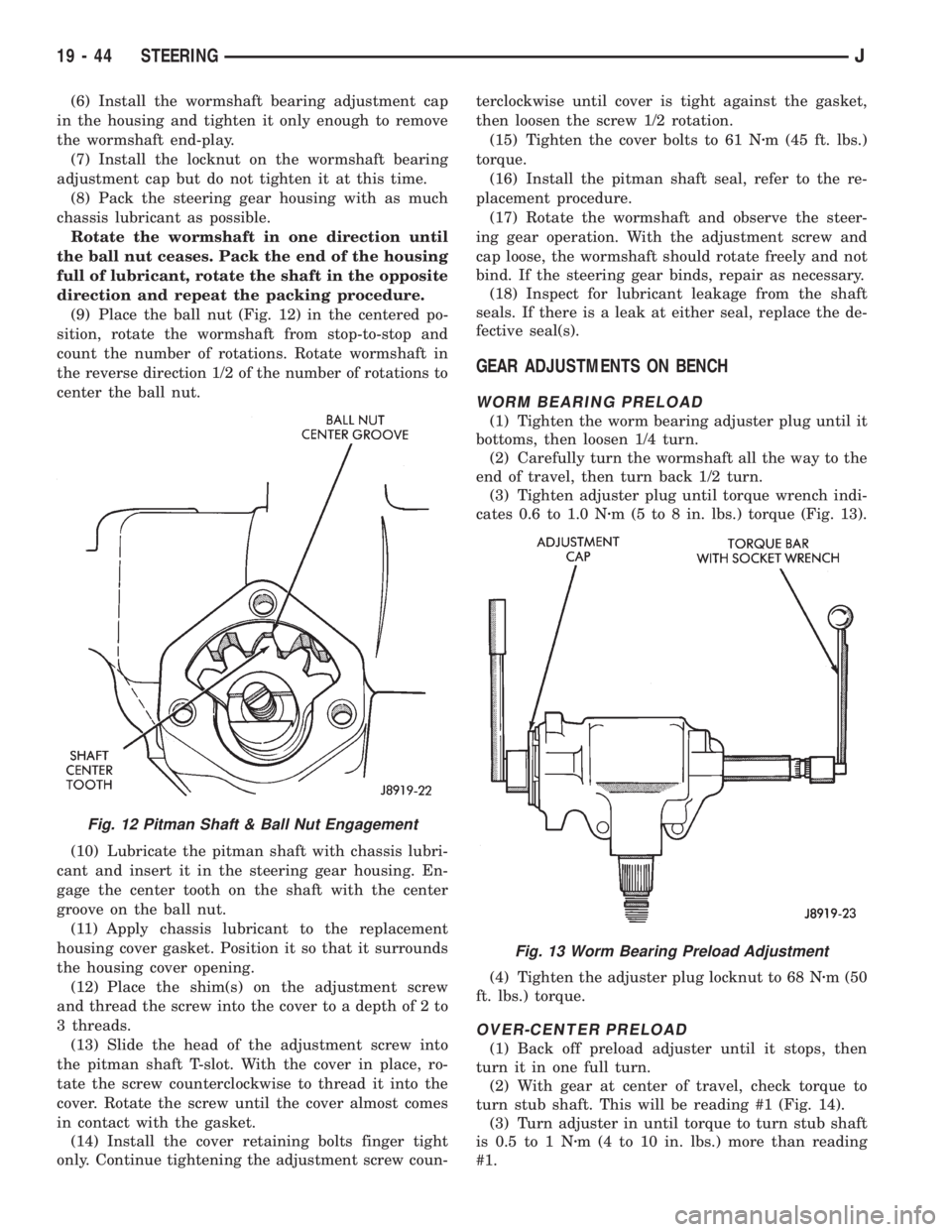
(9) Place the ball nut (Fig. 12) in the centered po-
sition, rotate the wormshaft from stop-to-stop and
count the number of rotations. Rotate wormshaft in
the reverse direction 1/2 of the number of rotations to
center the ball nut.
(10) Lubricate the pitman shaft with chassis lubri-
cant and insert it in the steering gear housing. En-
gage the center tooth on the shaft with the center
groove on the ball nut.
(11) Apply chassis lubricant to the replacement
housing cover gasket. Position it so that it surrounds
the housing cover opening.
(12) Place the shim(s) on the adjustment screw
and thread the screw into the cover to a depth of 2 to
3 threads.
(13) Slide the head of the adjustment screw into
the pitman shaft T-slot. With the cover in place, ro-
tate the screw counterclockwise to thread it into the
cover. Rotate the screw until the cover almost comes
in contact with the gasket.
(14) Install the cover retaining bolts finger tight
only. Continue tightening the adjustment screw coun-terclockwise until cover is tight against the gasket,
then loosen the screw 1/2 rotation.
(15) Tighten the cover bolts to 61 Nzm (45 ft. lbs.)
torque.
(16) Install the pitman shaft seal, refer to the re-
placement procedure.
(17) Rotate the wormshaft and observe the steer-
ing gear operation. With the adjustment screw and
cap loose, the wormshaft should rotate freely and not
bind. If the steering gear binds, repair as necessary.
(18) Inspect for lubricant leakage from the shaft
seals. If there is a leak at either seal, replace the de-
fective seal(s).
GEAR ADJUSTMENTS ON BENCH
WORM BEARING PRELOAD
(1) Tighten the worm bearing adjuster plug until it
bottoms, then loosen 1/4 turn.
(2) Carefully turn the wormshaft all the way to the
end of travel, then turn back 1/2 turn.
(3) Tighten adjuster plug until torque wrench indi-
cates 0.6 to 1.0 Nzm (5 to 8 in. lbs.) torque (Fig. 13).
(4) Tighten the adjuster plug locknut to 68 Nzm (50
ft. lbs.) torque.
OVER-CENTER PRELOAD
(1) Back off preload adjuster until it stops, then
turn it in one full turn.
(2) With gear at center of travel, check torque to
turn stub shaft. This will be reading #1 (Fig. 14).
(3) Turn adjuster in until torque to turn stub shaft
is 0.5 to 1 Nzm (4 to 10 in. lbs.) more than reading
#1.
Fig. 12 Pitman Shaft & Ball Nut Engagement
Fig. 13 Worm Bearing Preload Adjustment
19 - 44 STEERINGJ
Page 1529 of 2158
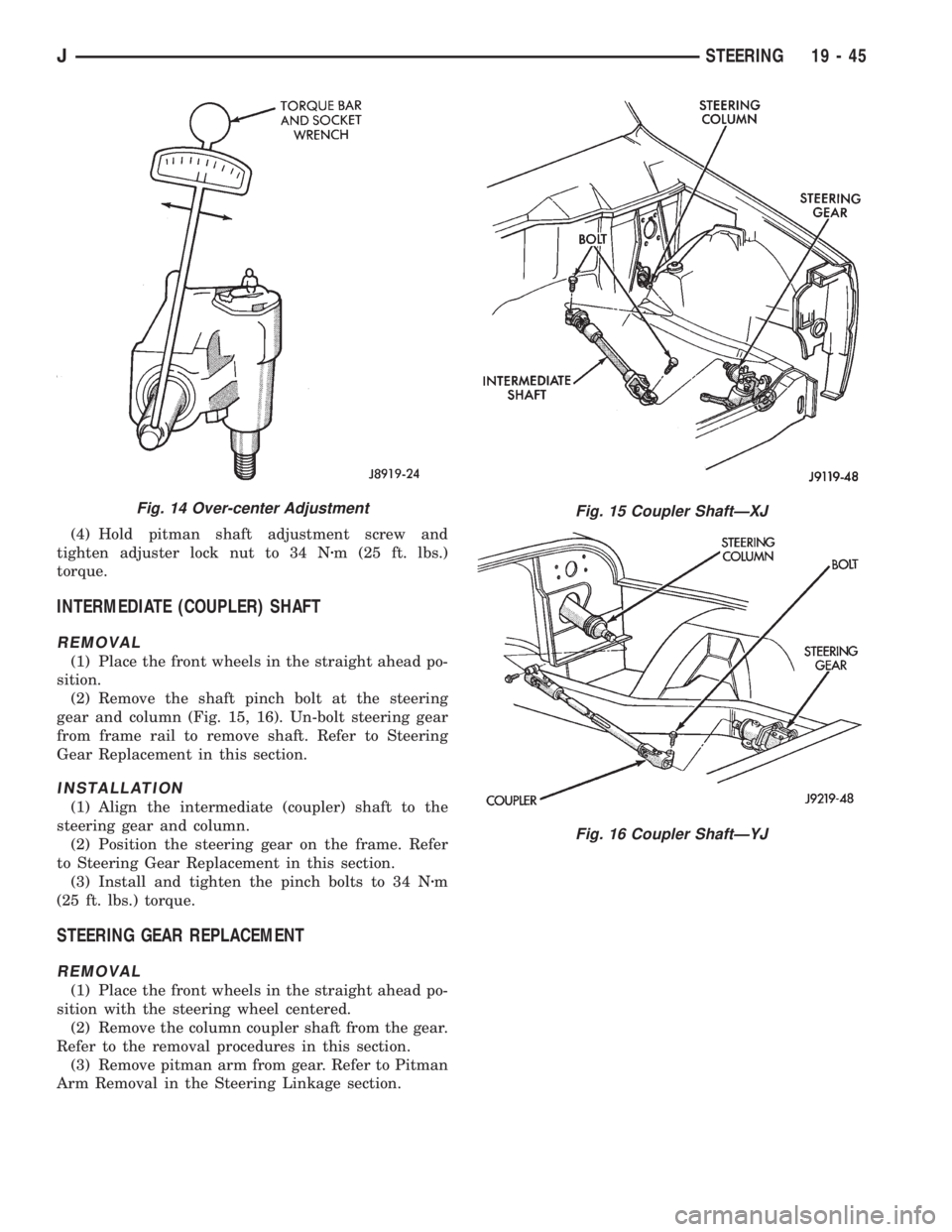
(4) Hold pitman shaft adjustment screw and
tighten adjuster lock nut to 34 Nzm (25 ft. lbs.)
torque.
INTERMEDIATE (COUPLER) SHAFT
REMOVAL
(1) Place the front wheels in the straight ahead po-
sition.
(2) Remove the shaft pinch bolt at the steering
gear and column (Fig. 15, 16). Un-bolt steering gear
from frame rail to remove shaft. Refer to Steering
Gear Replacement in this section.
INSTALLATION
(1) Align the intermediate (coupler) shaft to the
steering gear and column.
(2) Position the steering gear on the frame. Refer
to Steering Gear Replacement in this section.
(3) Install and tighten the pinch bolts to 34 Nzm
(25 ft. lbs.) torque.
STEERING GEAR REPLACEMENT
REMOVAL
(1) Place the front wheels in the straight ahead po-
sition with the steering wheel centered.
(2) Remove the column coupler shaft from the gear.
Refer to the removal procedures in this section.
(3) Remove pitman arm from gear. Refer to Pitman
Arm Removal in the Steering Linkage section.
Fig. 14 Over-center AdjustmentFig. 15 Coupler ShaftÐXJ
Fig. 16 Coupler ShaftÐYJ
JSTEERING 19 - 45
Page 1530 of 2158
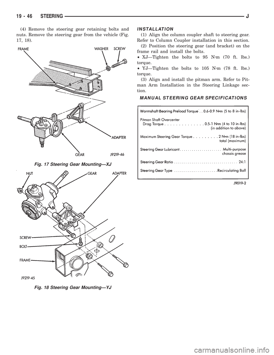
(4) Remove the steering gear retaining bolts and
nuts. Remove the steering gear from the vehicle (Fig.
17, 18).INSTALLATION
(1) Align the column coupler shaft to steering gear.
Refer to Column Coupler installation in this section.
(2) Position the steering gear (and bracket) on the
frame rail and install the bolts.
²XJÐTighten the bolts to 95 Nzm (70 ft. lbs.)
torque.
²YJÐTighten the bolts to 105 Nzm (78 ft. lbs.)
torque.
(3) Align and install the pitman arm. Refer to Pit-
man Arm Installation in the Steering Linkage sec-
tion.
Fig. 17 Steering Gear MountingÐXJ
Fig. 18 Steering Gear MountingÐYJ
MANUAL STEERING GEAR SPECIFICATIONS
19 - 46 STEERINGJ