JEEP XJ 1995 Service And Repair Manual
Manufacturer: JEEP, Model Year: 1995, Model line: XJ, Model: JEEP XJ 1995Pages: 2158, PDF Size: 81.9 MB
Page 2071 of 2158
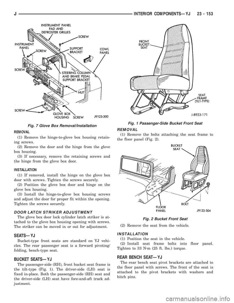
REMOVAL
(1) Remove the hinge-to-glove box housing retain-
ing screws.
(2) Remove the door and the hinge from the glove
box housing.
(3) If necessary, remove the retaining screws and
the hinge from the glove box door.
INSTALLATION
(1) If removed, install the hinge on the glove box
door with screws. Tighten the screws securely.
(2) Position the glove box door and hinge on the
glove box housing.
(3) Install the hinge-to-glove box housing screws
and adjust the door for proper fit within the opening.
Tighten the screws securely.
DOOR LATCH STRIKER ADJUSTMENT
The glove box door lock cylinder latch striker is at-
tached to the glove box housing opening with screws.
The striker can be moved in or out for adjustment.
SEATSÐYJ
Bucket-type front seats are standard on YJ vehi-
cles. The rear passenger seat is a forward pivoting/
folding, bench-type seat.
BUCKET SEATSÐYJ
The passenger-side (RH), front bucket seat frame is
the tilt-type (Fig. 1). The driver-side (LH) seat is
fixed in-place. Both the passenger-side (RH) seat and
the driver-side (LH) seat have fore-and-aft track ad-
justment.
REMOVAL
(1) Remove the bolts attaching the seat frame to
the floor panel (Fig. 2).
(2) Remove the seat from the vehicle.
INSTALLATION
(1) Position the seat in the vehicle.
(2) Install seat frame bolts into floor panel.
Tighten to 33 Nzm (25 ft. lbs.) torque.
REAR BENCH SEATÐYJ
The rear bench seat pivot brackets are attached to
the floor panel with screws. The front of the seat is
attached to the pivot brackets with washers and
hitch pins.
Fig. 7 Glove Box Removal/InstallationFig. 1 Passenger-Side Bucket Front Seat
Fig. 2 Bucket Front Seat
JINTERIOR COMPONENTSÐYJ 23 - 153
Page 2072 of 2158
If the floor brackets are not to be replaced, it is not
necessary to remove the rear screws to remove the
rear seat. Follow step (3) for seat disengagement.
REMOVAL
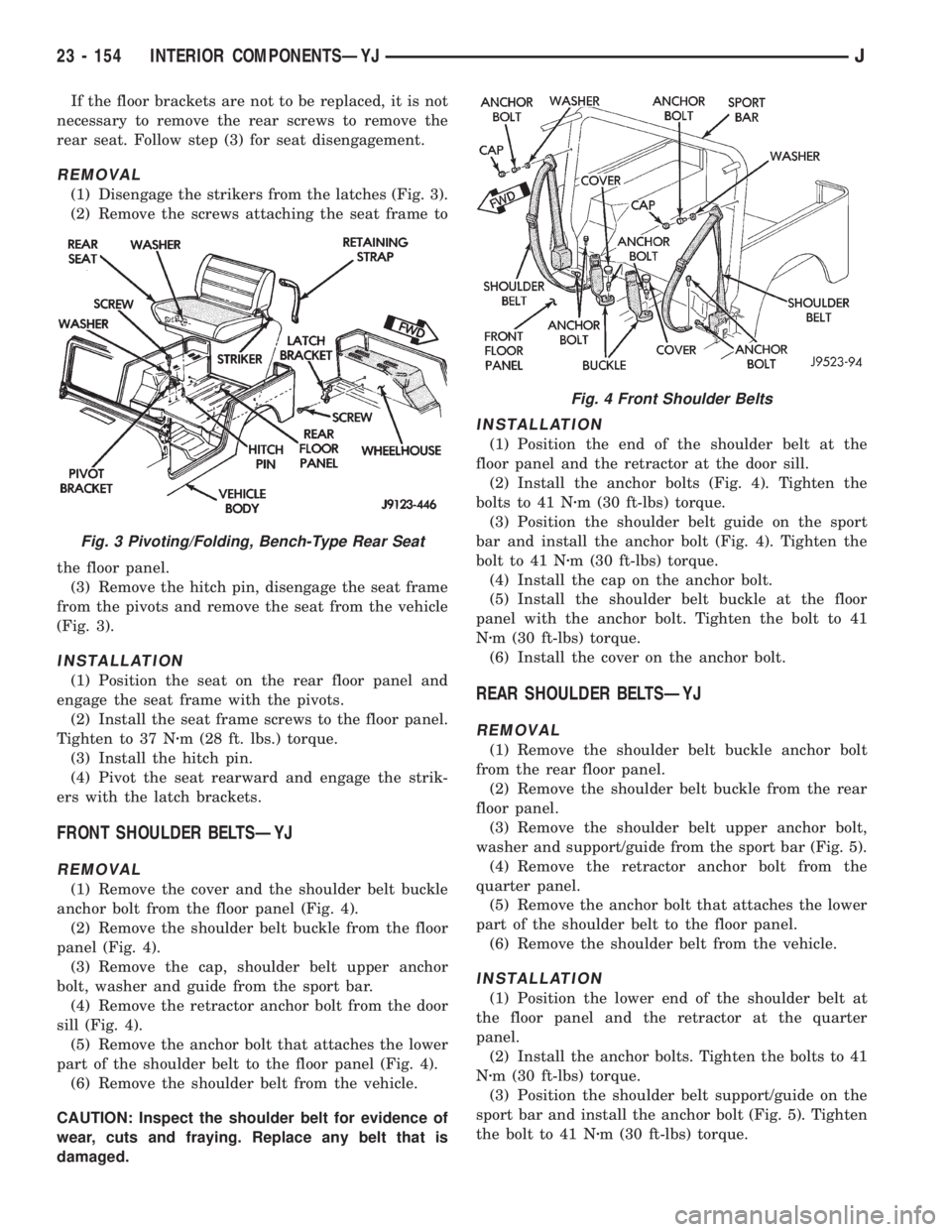
(1) Disengage the strikers from the latches (Fig. 3).
(2) Remove the screws attaching the seat frame to
the floor panel.
(3) Remove the hitch pin, disengage the seat frame
from the pivots and remove the seat from the vehicle
(Fig. 3).
INSTALLATION
(1) Position the seat on the rear floor panel and
engage the seat frame with the pivots.
(2) Install the seat frame screws to the floor panel.
Tighten to 37 Nzm (28 ft. lbs.) torque.
(3) Install the hitch pin.
(4) Pivot the seat rearward and engage the strik-
ers with the latch brackets.
FRONT SHOULDER BELTSÐYJ
REMOVAL
(1) Remove the cover and the shoulder belt buckle
anchor bolt from the floor panel (Fig. 4).
(2) Remove the shoulder belt buckle from the floor
panel (Fig. 4).
(3) Remove the cap, shoulder belt upper anchor
bolt, washer and guide from the sport bar.
(4) Remove the retractor anchor bolt from the door
sill (Fig. 4).
(5) Remove the anchor bolt that attaches the lower
part of the shoulder belt to the floor panel (Fig. 4).
(6) Remove the shoulder belt from the vehicle.
CAUTION: Inspect the shoulder belt for evidence of
wear, cuts and fraying. Replace any belt that is
damaged.
INSTALLATION
(1) Position the end of the shoulder belt at the
floor panel and the retractor at the door sill.
(2) Install the anchor bolts (Fig. 4). Tighten the
bolts to 41 Nzm (30 ft-lbs) torque.
(3) Position the shoulder belt guide on the sport
bar and install the anchor bolt (Fig. 4). Tighten the
bolt to 41 Nzm (30 ft-lbs) torque.
(4) Install the cap on the anchor bolt.
(5) Install the shoulder belt buckle at the floor
panel with the anchor bolt. Tighten the bolt to 41
Nzm (30 ft-lbs) torque.
(6) Install the cover on the anchor bolt.
REAR SHOULDER BELTSÐYJ
REMOVAL
(1) Remove the shoulder belt buckle anchor bolt
from the rear floor panel.
(2) Remove the shoulder belt buckle from the rear
floor panel.
(3) Remove the shoulder belt upper anchor bolt,
washer and support/guide from the sport bar (Fig. 5).
(4) Remove the retractor anchor bolt from the
quarter panel.
(5) Remove the anchor bolt that attaches the lower
part of the shoulder belt to the floor panel.
(6) Remove the shoulder belt from the vehicle.
INSTALLATION
(1) Position the lower end of the shoulder belt at
the floor panel and the retractor at the quarter
panel.
(2) Install the anchor bolts. Tighten the bolts to 41
Nzm (30 ft-lbs) torque.
(3) Position the shoulder belt support/guide on the
sport bar and install the anchor bolt (Fig. 5). Tighten
the bolt to 41 Nzm (30 ft-lbs) torque.
Fig. 3 Pivoting/Folding, Bench-Type Rear Seat
Fig. 4 Front Shoulder Belts
23 - 154 INTERIOR COMPONENTSÐYJJ
Page 2073 of 2158
(4) Install the shoulder belt buckle at the floor
panel with the anchor bolt. Tighten the bolt to 41
Nzm (30 ft-lbs) torque.
SUNVISORSÐYJ
REMOVAL
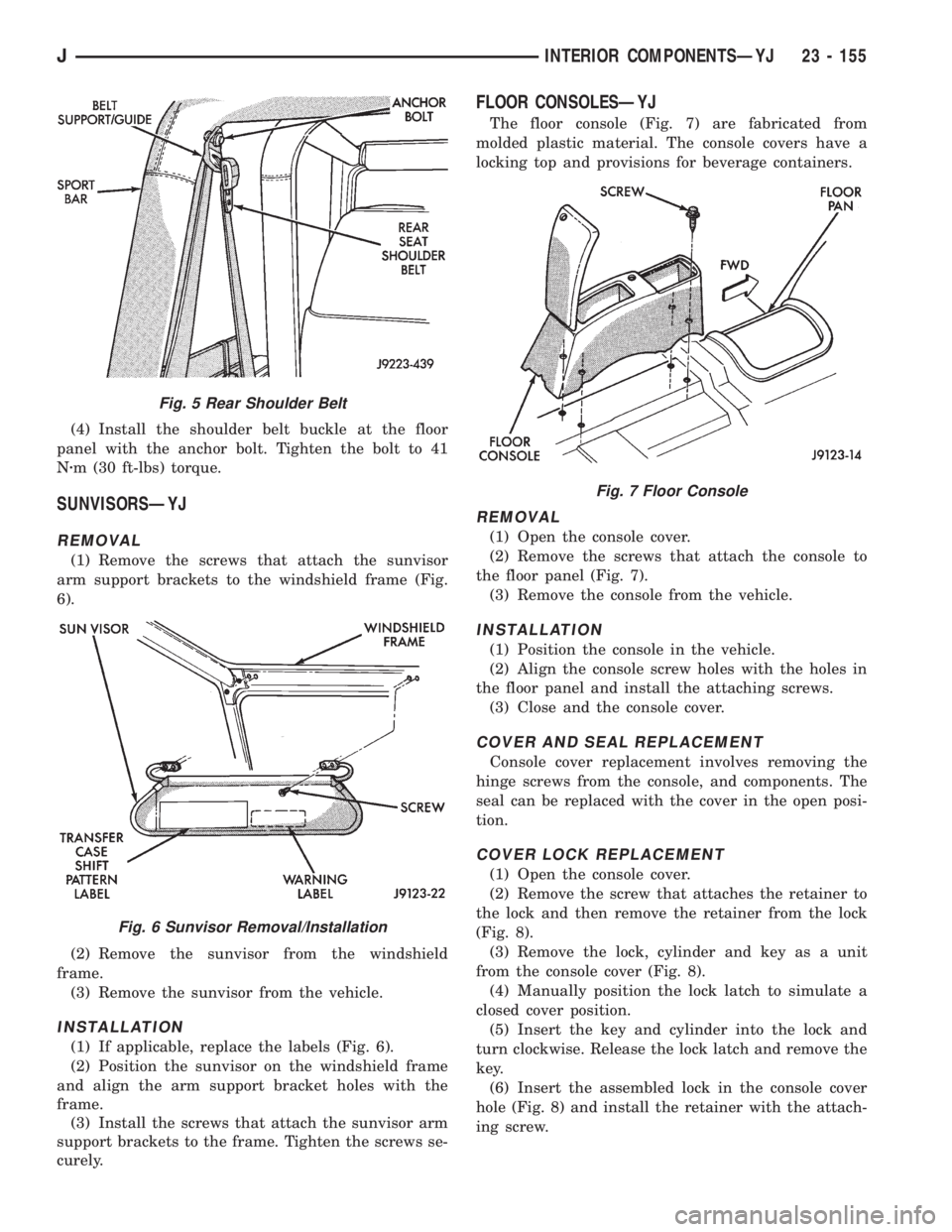
(1) Remove the screws that attach the sunvisor
arm support brackets to the windshield frame (Fig.
6).
(2) Remove the sunvisor from the windshield
frame.
(3) Remove the sunvisor from the vehicle.
INSTALLATION
(1) If applicable, replace the labels (Fig. 6).
(2) Position the sunvisor on the windshield frame
and align the arm support bracket holes with the
frame.
(3) Install the screws that attach the sunvisor arm
support brackets to the frame. Tighten the screws se-
curely.
FLOOR CONSOLESÐYJ
The floor console (Fig. 7) are fabricated from
molded plastic material. The console covers have a
locking top and provisions for beverage containers.
REMOVAL
(1) Open the console cover.
(2) Remove the screws that attach the console to
the floor panel (Fig. 7).
(3) Remove the console from the vehicle.
INSTALLATION
(1) Position the console in the vehicle.
(2) Align the console screw holes with the holes in
the floor panel and install the attaching screws.
(3) Close and the console cover.
COVER AND SEAL REPLACEMENT
Console cover replacement involves removing the
hinge screws from the console, and components. The
seal can be replaced with the cover in the open posi-
tion.
COVER LOCK REPLACEMENT
(1) Open the console cover.
(2) Remove the screw that attaches the retainer to
the lock and then remove the retainer from the lock
(Fig. 8).
(3) Remove the lock, cylinder and key as a unit
from the console cover (Fig. 8).
(4) Manually position the lock latch to simulate a
closed cover position.
(5) Insert the key and cylinder into the lock and
turn clockwise. Release the lock latch and remove the
key.
(6) Insert the assembled lock in the console cover
hole (Fig. 8) and install the retainer with the attach-
ing screw.
Fig. 5 Rear Shoulder Belt
Fig. 6 Sunvisor Removal/Installation
Fig. 7 Floor Console
JINTERIOR COMPONENTSÐYJ 23 - 155
Page 2074 of 2158
CARPETÐYJ
PASSENGER COMPARTMENT FRONT CARPET
SECTION
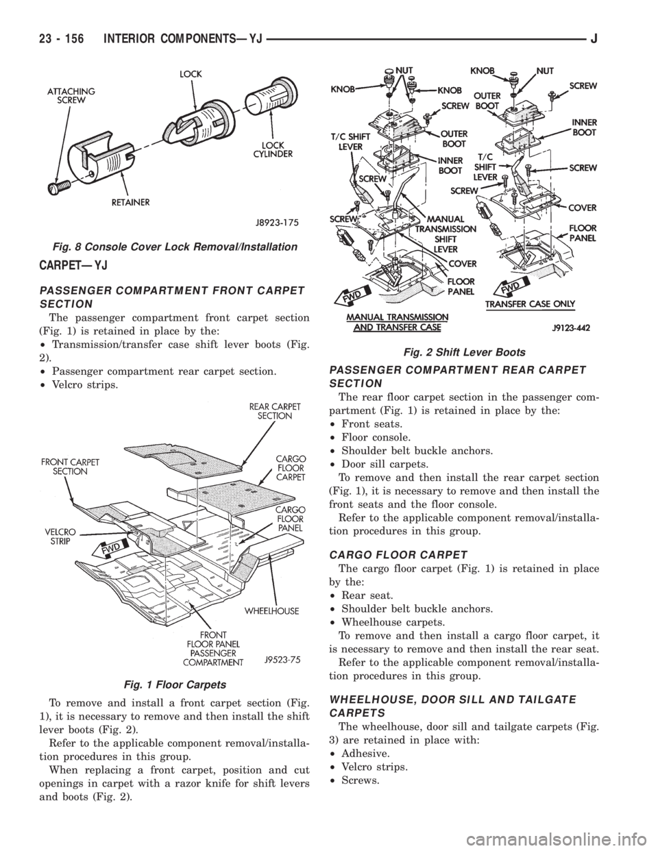
The passenger compartment front carpet section
(Fig. 1) is retained in place by the:
²Transmission/transfer case shift lever boots (Fig.
2).
²Passenger compartment rear carpet section.
²Velcro strips.
To remove and install a front carpet section (Fig.
1), it is necessary to remove and then install the shift
lever boots (Fig. 2).
Refer to the applicable component removal/installa-
tion procedures in this group.
When replacing a front carpet, position and cut
openings in carpet with a razor knife for shift levers
and boots (Fig. 2).
PASSENGER COMPARTMENT REAR CARPET
SECTION
The rear floor carpet section in the passenger com-
partment (Fig. 1) is retained in place by the:
²Front seats.
²Floor console.
²Shoulder belt buckle anchors.
²Door sill carpets.
To remove and then install the rear carpet section
(Fig. 1), it is necessary to remove and then install the
front seats and the floor console.
Refer to the applicable component removal/installa-
tion procedures in this group.
CARGO FLOOR CARPET
The cargo floor carpet (Fig. 1) is retained in place
by the:
²Rear seat.
²Shoulder belt buckle anchors.
²Wheelhouse carpets.
To remove and then install a cargo floor carpet, it
is necessary to remove and then install the rear seat.
Refer to the applicable component removal/installa-
tion procedures in this group.
WHEELHOUSE, DOOR SILL AND TAILGATE
CARPETS
The wheelhouse, door sill and tailgate carpets (Fig.
3) are retained in place with:
²Adhesive.
²Velcro strips.
²Screws.
Fig. 8 Console Cover Lock Removal/Installation
Fig. 1 Floor Carpets
Fig. 2 Shift Lever Boots
23 - 156 INTERIOR COMPONENTSÐYJJ
Page 2075 of 2158
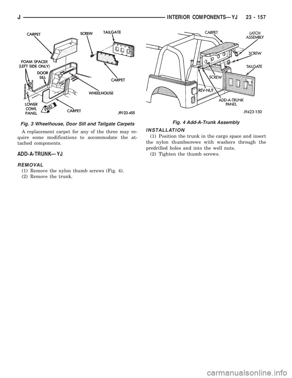
A replacement carpet for any of the three may re-
quire some modifications to accommodate the at-
tached components.
ADD-A-TRUNKÐYJ
REMOVAL
(1) Remove the nylon thumb screws (Fig. 4).
(2) Remove the trunk.
INSTALLATION
(1) Position the trunk in the cargo space and insert
the nylon thumbscrews with washers through the
predrilled holes and into the well nuts.
(2) Tighten the thumb screws.
Fig. 3 Wheelhouse, Door Sill and Tailgate CarpetsFig. 4 Add-A-Trunk Assembly
JINTERIOR COMPONENTSÐYJ 23 - 157
Page 2076 of 2158
PAINT
INTRODUCTION
Exterior vehicle body colors are identified on the
Vehicle Code plate. The plate is located on the left
side of the dash panel in the engine compartment.
The color code location is described in the Introduc-
tion of this manual. The color names provided in the
Paint and Trim Code Description chart are the color
names used on most repair product containers. The
color names in the new vehicle ordering guides may
vary depending on vehicle line but use the same color
code.
BASE COAT/CLEAR COAT FINISH
On most vehicles a two part paint application (base
coat/clear coat) is used. Color paint that is applied to
primer is called base coat. The clear coat protects the
base coat from ultra violet light and provides a dura-
ble high gloss finish.
WET SANDING,BUFFING AND POLISHING
Minor acid etching, orange peel or smudging in
clear coat can be reduced with light wet sanding,
hand buffing and polishing. If the finish has been
wet sanded in the past, it can not be repeated. Wet
sanding operation should be performed by a trained
automotive painter.
CAUTION: Do not remove clear coat finish, if
equipped. Base coat paint must retain clear coat to
shine.
PAINTED SURFACE TOUCH-UP
When a painted metal surface has been scratched
or chipped, it should be touched-up as soon as possi-ble to avoid corrosion. For best results, use Mopar
Scratch Filler/Primer, Touch-Up Paints and Clear Top
Coat. Refer to Introduction group of this manual for
Body Code Plate information.
TOUCH-UP PROCEDURE
(1) Scrape loose paint and corrosion from inside
scratch or chip.
(2) Clean affected area with Mopar Tar/Road Oil
Remover and allow to dry.
(3) Fill the inside of the scratch or chip with a coat
of filler/primer. Do not overlap primer onto good sur-
face finish. The applicator brush should be wet
enough to puddle fill the defect without running. Do
not stroke brush applicator on body surface. Allow
the filler/ primer to dry hard.
(4) Cover the filler/primer with color touch-up
paint. Do not overlap touch-up color onto the original
color coat around the scratch or chip. Butt the new
color to the original color if possible. Do not stroke
applicator brush on body surface. Allow touch-up
paint to dry hard.
(5) On vehicles without clear coat, the touch-up
color can be lightly (600 grit) wet sanded and pol-
ished with rubbing compound.
(6) On vehicles with clear coat, Apply clear top
coat to touch-up paint with the same technique as
described in step 4. Allow clear top coat to dry hard.
If desired, step 5 can be performed on clear top coat.
23 - 158 PAINTÐXJÐYJJ
Page 2077 of 2158
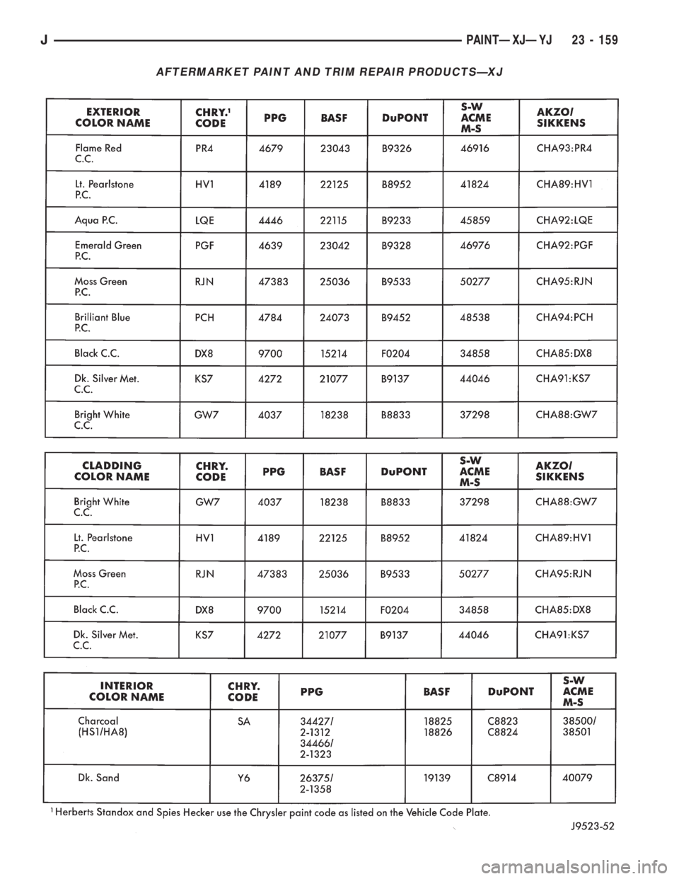
AFTERMARKET PAINT AND TRIM REPAIR PRODUCTSÐXJ
JPAINTÐXJÐYJ 23 - 159
Page 2078 of 2158
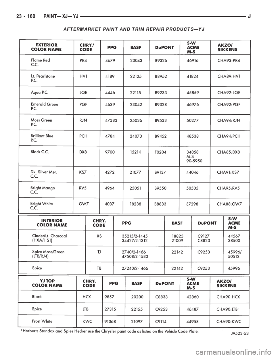
AFTERMARKET PAINT AND TRIM REPAIR PRODUCTSÐYJ
23 - 160 PAINTÐXJÐYJJ
Page 2079 of 2158
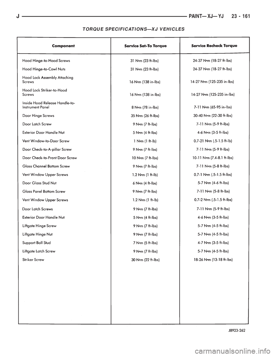
TORQUE SPECIFICATIONSÐXJ VEHICLES
JPAINTÐXJÐYJ 23 - 161
Page 2080 of 2158
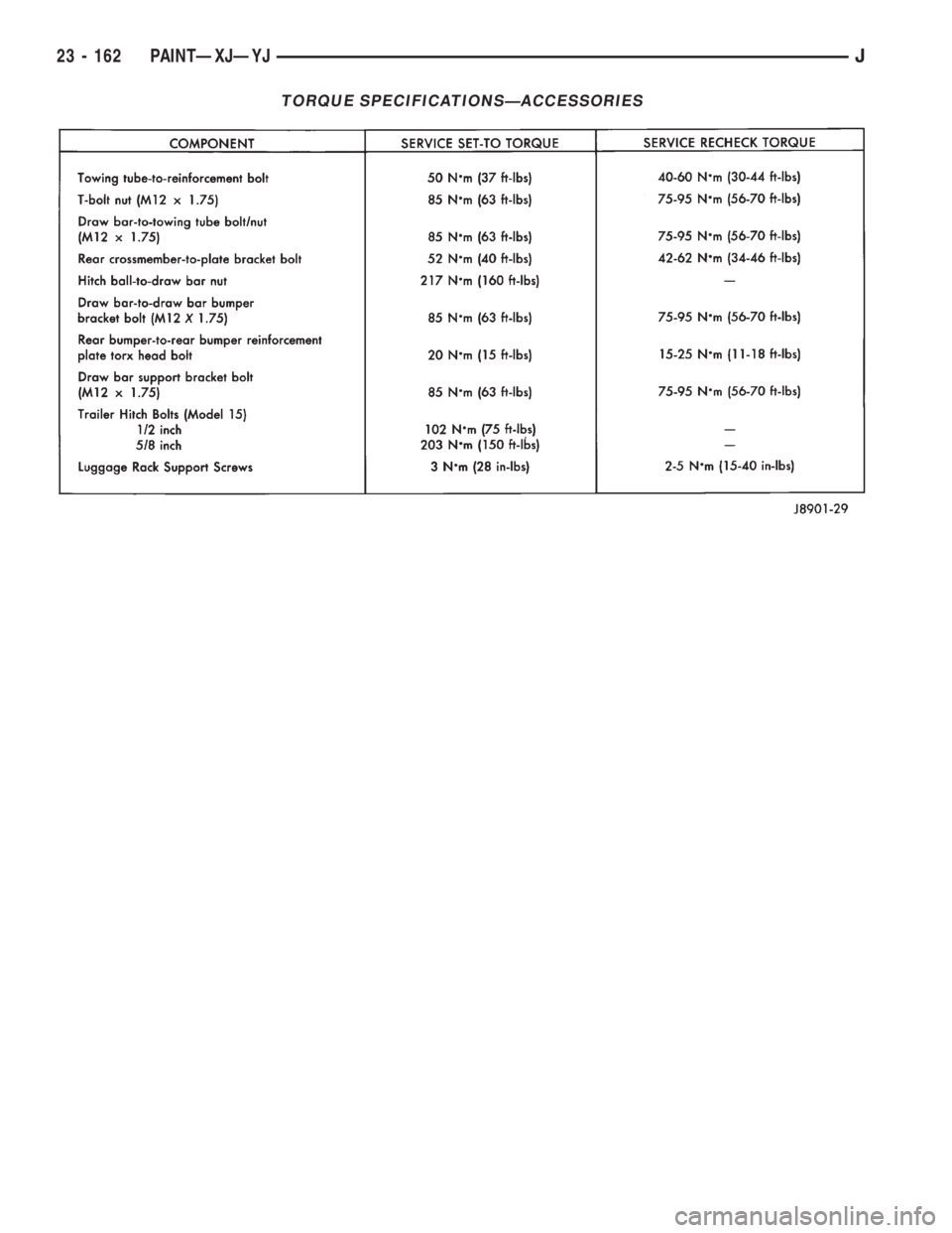
TORQUE SPECIFICATIONSÐACCESSORIES
23 - 162 PAINTÐXJÐYJJ