speaker JEEP XJ 1995 Service And Repair Manual
[x] Cancel search | Manufacturer: JEEP, Model Year: 1995, Model line: XJ, Model: JEEP XJ 1995Pages: 2158, PDF Size: 81.9 MB
Page 401 of 2158
AUDIO SYSTEMS
CONTENTS
page page
DIAGNOSIS............................. 2
GENERAL INFORMATION.................. 1SERVICE PROCEDURES................... 6
GENERAL INFORMATION
Following are general descriptions of major compo-
nents used in XJ (Cherokee)/YJ (Wrangler) audio sys-
tems. Refer to Group 8W - Wiring Diagrams for
complete circuit descriptions and diagrams.
RADIOS
Radio options for the XJ and YJ models include an
AM/FM stereo or an AM/FM stereo/cassette receiver.
Both units are Electronically-Tuned Radios (ETR)
and include a clock function. For more information
on radio features, setting procedures, and control
functions refer to the owner's manual.
IN-LINE FUSE
Each radio receives fused battery feed when the ig-
nition switch is in the ON or ACCESSORY position.
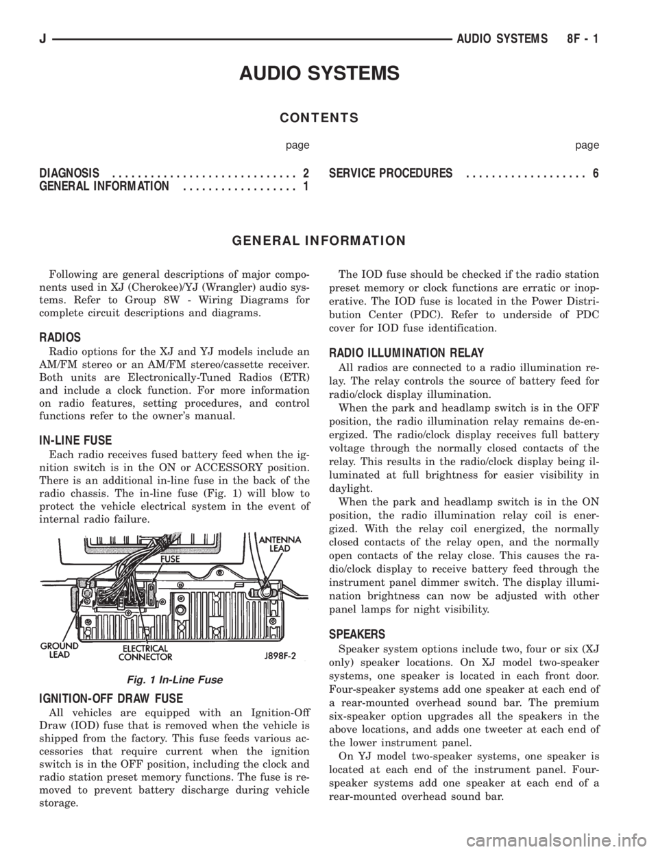
There is an additional in-line fuse in the back of the
radio chassis. The in-line fuse (Fig. 1) will blow to
protect the vehicle electrical system in the event of
internal radio failure.
IGNITION-OFF DRAW FUSE
All vehicles are equipped with an Ignition-Off
Draw (IOD) fuse that is removed when the vehicle is
shipped from the factory. This fuse feeds various ac-
cessories that require current when the ignition
switch is in the OFF position, including the clock and
radio station preset memory functions. The fuse is re-
moved to prevent battery discharge during vehicle
storage.The IOD fuse should be checked if the radio station
preset memory or clock functions are erratic or inop-
erative. The IOD fuse is located in the Power Distri-
bution Center (PDC). Refer to underside of PDC
cover for IOD fuse identification.
RADIO ILLUMINATION RELAY
All radios are connected to a radio illumination re-
lay. The relay controls the source of battery feed for
radio/clock display illumination.
When the park and headlamp switch is in the OFF
position, the radio illumination relay remains de-en-
ergized. The radio/clock display receives full battery
voltage through the normally closed contacts of the
relay. This results in the radio/clock display being il-
luminated at full brightness for easier visibility in
daylight.
When the park and headlamp switch is in the ON
position, the radio illumination relay coil is ener-
gized. With the relay coil energized, the normally
closed contacts of the relay open, and the normally
open contacts of the relay close. This causes the ra-
dio/clock display to receive battery feed through the
instrument panel dimmer switch. The display illumi-
nation brightness can now be adjusted with other
panel lamps for night visibility.
SPEAKERS
Speaker system options include two, four or six (XJ
only) speaker locations. On XJ model two-speaker
systems, one speaker is located in each front door.
Four-speaker systems add one speaker at each end of
a rear-mounted overhead sound bar. The premium
six-speaker option upgrades all the speakers in the
above locations, and adds one tweeter at each end of
the lower instrument panel.
On YJ model two-speaker systems, one speaker is
located at each end of the instrument panel. Four-
speaker systems add one speaker at each end of a
rear-mounted overhead sound bar.
Fig. 1 In-Line Fuse
JAUDIO SYSTEMS 8F - 1
Page 402 of 2158
ANTENNA
All models use a fixed-length stainless steel rod-
type antenna mast, installed at the right front (fend-
er on XJ, cowl side on YJ) of the vehicle. The
antenna mast is connected to the center wire of the
coaxial antenna cable and is not grounded to any
part of the vehicle.
To eliminate static, the antenna base must have a
good ground. The coaxial antenna cable shield (the
outer wire mesh of the cable) is grounded to the an-
tenna base and the radio chassis.
The factory installed ETRs automatically compen-
sate for radio antenna trim. Therefore, no antenna
trimmer adjustment is required or possible when re-
placing the receiver or the antenna.
RADIO NOISE SUPPRESSION
Radio Frequency Interference (RFI) and Electro-
Magnetic Interference (EMI) noise suppression is ac-
complished primarily through circuitry internal to
the radio receivers. These internal suppression de-
vices are only serviced as a part of the radio receiver.External suppression devices that are serviceable
and should be checked in the case of RFI or EMI
noise complaints include the following:
²radio antenna base ground
²engine-to-body ground strap
²resistor-type spark plugs
²radio suppression-type secondary ignition wiring.
In addition, if the source of RFI or EMI noise is
identified as a component on the vehicle (i.e.:genera-
tor, blower motor, etc.), the ground path for that com-
ponent should be checked. If excessive resistance is
found in that circuit, repair as required before con-
sidering any component replacement.
Fleet vehicles are available with an extra-cost RFI-
suppressed Powertrain Control Module (PCM). This
unit reduces interference generated by the PCM on
some radio frequencies used in two-way radio com-
munications. However, this unit will not resolve com-
plaints of RFI in the commercial AM or FM radio
frequency ranges.
DIAGNOSIS
RADIO
CAUTION: Do not operate the radio with speaker
leads detached since damage to the transistors
may result.
(1) Check fuse 2 in fuseblock module and fuse in
back of radio chassis. If OK, go to next step. If not
OK, replace fuse.
(2) Turn ignition switch to ON position. Check for
battery voltage at fuse 2. If OK, go to next step. If
not OK, repair circuit to ignition switch as required.
(3) Turn ignition switch to OFF position. Discon-
nect battery negative cable. Remove instrument clus-
ter bezel. Remove radio, but do not unplug any
connections. Check for continuity between the radio
chassis and a good ground. There should be continu-
ity. If OK, go to next step. If not OK, repair radio
ground circuit as required.
(4) Connect battery negative cable. Turn ignition
switch to ON position. See Radio Connections chart.
Check for battery voltage at cavity 3 of radio connec-
tor. If OK, go to next step. If not OK, repair circuit to
fuse 2 as required.
(5) Turn ignition switch to OFF position. Check for
battery voltage at cavity 4 of radio connector. If OK,
replace radio. If not OK, repair circuit to IOD fuse in
PDC as required.
SPEAKERS
CAUTION: Do not operate the radio with speaker
leads detached since damage to the transistors
may result.
(1) Turn radio on and adjust balance and fader
controls to check performance of each individual
speaker. Note the speaker locations that are not per-
forming correctly. Go to next step.
(2) Turn radio off. Disconnect battery negative ca-
ble. Remove instrument cluster bezel and remove ra-
dio. See Radio Connections chart. Check both the
speaker feed and return cavities at radio for continu-
ity to a good ground. There should be no continuity.
If OK, go to next step. If not OK, repair wiring cir-
cuit as required.
(3) Check resistance between speaker feed and re-
turn cavities. Meter should read between 3 and 8
ohms (speaker impedance). If OK, see diagnosis for
Radio. If not OK, go to next step.
(4) Unplug speaker wiring connector. Check for
continuity between speaker feed cavity at radio and
at speaker. Repeat check between speaker return
cavity at radio and at speaker. If OK, replace
speaker. If not OK, repair wiring circuit as required.
8F - 2 AUDIO SYSTEMSJ
Page 406 of 2158
SERVICE PROCEDURES
RADIO REMOVE/INSTALL - XJ
(1) Disconnect battery negative cable.
(2) Remove upper and lower steering column
shrouds and steering column to instrument panel be-
zel gap hider. If equipped with tilt steering, apply
tape to tilt mechanism on top of steering column to
protect instrument panel bezel from damage during
removal.
(3) Remove 4 instrument panel bezel attaching
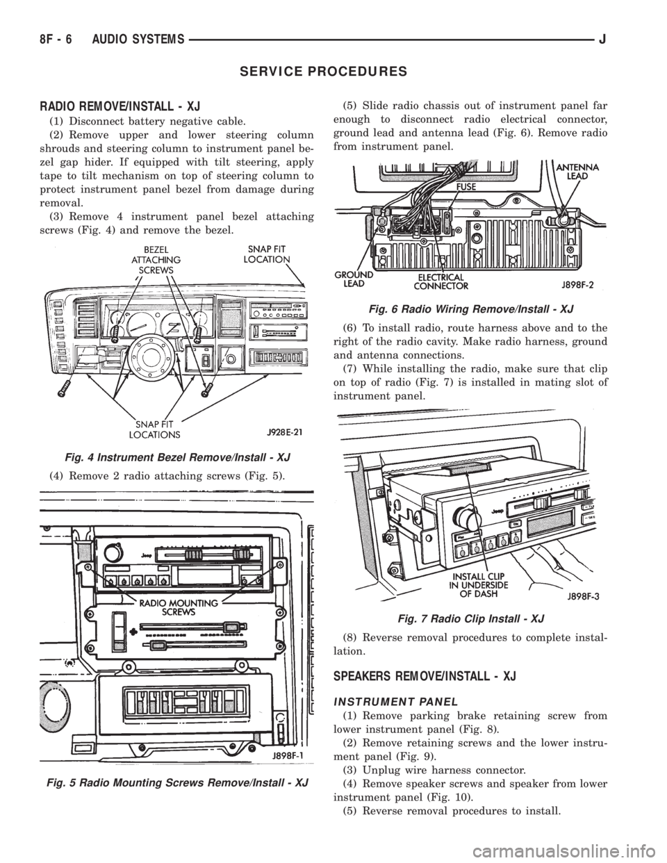
screws (Fig. 4) and remove the bezel.
(4) Remove 2 radio attaching screws (Fig. 5).(5) Slide radio chassis out of instrument panel far
enough to disconnect radio electrical connector,
ground lead and antenna lead (Fig. 6). Remove radio
from instrument panel.
(6) To install radio, route harness above and to the
right of the radio cavity. Make radio harness, ground
and antenna connections.
(7) While installing the radio, make sure that clip
on top of radio (Fig. 7) is installed in mating slot of
instrument panel.
(8) Reverse removal procedures to complete instal-
lation.
SPEAKERS REMOVE/INSTALL - XJ
INSTRUMENT PANEL
(1) Remove parking brake retaining screw from
lower instrument panel (Fig. 8).
(2) Remove retaining screws and the lower instru-
ment panel (Fig. 9).
(3) Unplug wire harness connector.
(4) Remove speaker screws and speaker from lower
instrument panel (Fig. 10).
(5) Reverse removal procedures to install.
Fig. 4 Instrument Bezel Remove/Install - XJ
Fig. 5 Radio Mounting Screws Remove/Install - XJ
Fig. 6 Radio Wiring Remove/Install - XJ
Fig. 7 Radio Clip Install - XJ
8F - 6 AUDIO SYSTEMSJ
Page 407 of 2158
FRONT DOOR
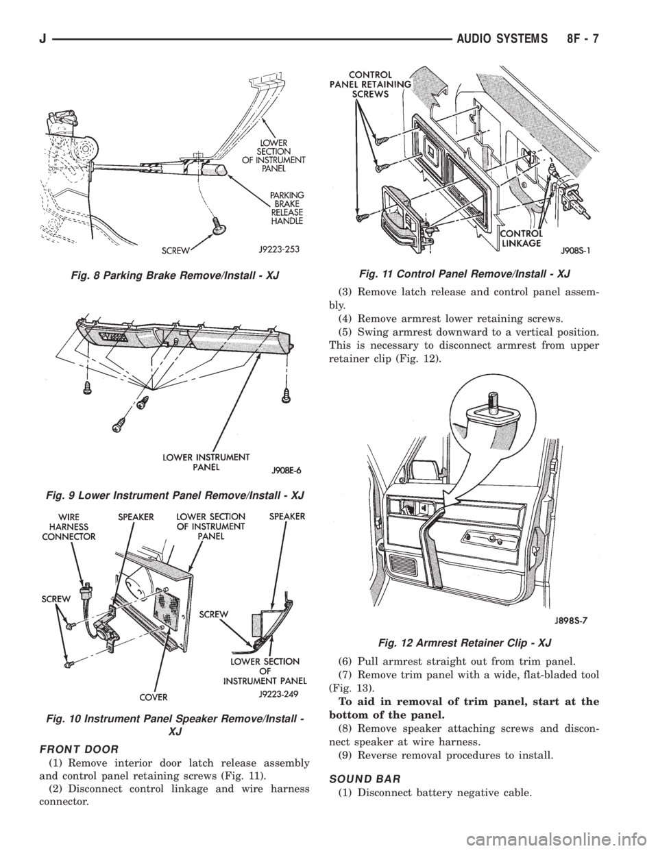
(1) Remove interior door latch release assembly
and control panel retaining screws (Fig. 11).
(2) Disconnect control linkage and wire harness
connector.(3) Remove latch release and control panel assem-
bly.
(4) Remove armrest lower retaining screws.
(5) Swing armrest downward to a vertical position.
This is necessary to disconnect armrest from upper
retainer clip (Fig. 12).
(6) Pull armrest straight out from trim panel.
(7) Remove trim panel with a wide, flat-bladed tool
(Fig. 13).
To aid in removal of trim panel, start at the
bottom of the panel.
(8) Remove speaker attaching screws and discon-
nect speaker at wire harness.
(9) Reverse removal procedures to install.
SOUND BAR
(1) Disconnect battery negative cable.
Fig. 8 Parking Brake Remove/Install - XJ
Fig. 9 Lower Instrument Panel Remove/Install - XJ
Fig. 10 Instrument Panel Speaker Remove/Install -
XJ
Fig. 11 Control Panel Remove/Install - XJ
Fig. 12 Armrest Retainer Clip - XJ
JAUDIO SYSTEMS 8F - 7
Page 408 of 2158
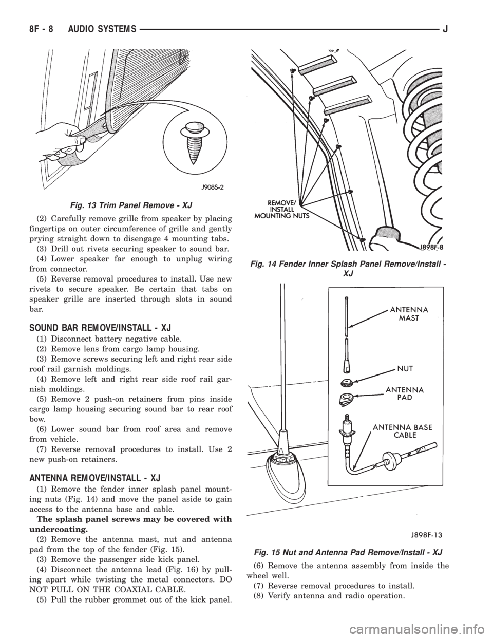
(2) Carefully remove grille from speaker by placing
fingertips on outer circumference of grille and gently
prying straight down to disengage 4 mounting tabs.
(3) Drill out rivets securing speaker to sound bar.
(4) Lower speaker far enough to unplug wiring
from connector.
(5) Reverse removal procedures to install. Use new
rivets to secure speaker. Be certain that tabs on
speaker grille are inserted through slots in sound
bar.
SOUND BAR REMOVE/INSTALL - XJ
(1) Disconnect battery negative cable.
(2) Remove lens from cargo lamp housing.
(3) Remove screws securing left and right rear side
roof rail garnish moldings.
(4) Remove left and right rear side roof rail gar-
nish moldings.
(5) Remove 2 push-on retainers from pins inside
cargo lamp housing securing sound bar to rear roof
bow.
(6) Lower sound bar from roof area and remove
from vehicle.
(7) Reverse removal procedures to install. Use 2
new push-on retainers.
ANTENNA REMOVE/INSTALL - XJ
(1) Remove the fender inner splash panel mount-
ing nuts (Fig. 14) and move the panel aside to gain
access to the antenna base and cable.
The splash panel screws may be covered with
undercoating.
(2) Remove the antenna mast, nut and antenna
pad from the top of the fender (Fig. 15).
(3) Remove the passenger side kick panel.
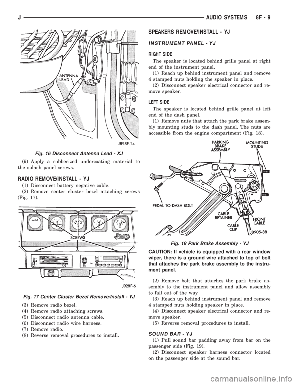
(4) Disconnect the antenna lead (Fig. 16) by pull-
ing apart while twisting the metal connectors. DO
NOT PULL ON THE COAXIAL CABLE.
(5) Pull the rubber grommet out of the kick panel.(6) Remove the antenna assembly from inside the
wheel well.
(7) Reverse removal procedures to install.
(8) Verify antenna and radio operation.
Fig. 13 Trim Panel Remove - XJ
Fig. 14 Fender Inner Splash Panel Remove/Install -
XJ
Fig. 15 Nut and Antenna Pad Remove/Install - XJ
8F - 8 AUDIO SYSTEMSJ
Page 409 of 2158
(9) Apply a rubberized undercoating material to
the splash panel screws.
RADIO REMOVE/INSTALL - YJ
(1) Disconnect battery negative cable.
(2) Remove center cluster bezel attaching screws
(Fig. 17).
(3) Remove radio bezel.
(4) Remove radio attaching screws.
(5) Disconnect radio antenna cable.
(6) Disconnect radio wire harness.
(7) Remove radio.
(8) Reverse removal procedures to install.
SPEAKERS REMOVE/INSTALL - YJ
INSTRUMENT PANEL - YJ
RIGHT SIDE
The speaker is located behind grille panel at right
end of the instrument panel.
(1) Reach up behind instrument panel and remove
4 stamped nuts holding the speaker in place.
(2) Disconnect speaker electrical connector and re-
move speaker.
LEFT SIDE
The speaker is located behind grille panel at left
end of the dash panel.
(1) Remove nuts that attach the park brake assem-
bly mounting studs to the dash panel. The nuts are
accessible from the engine compartment (Fig. 18).
CAUTION: If vehicle is equipped with a rear window
wiper, there is a ground wire attached to top of bolt
that attaches the park brake assembly to the instru-
ment panel.
(2) Remove bolt that attaches the park brake as-
sembly to the instrument panel and allow assembly
to fall out of the way.
(3) Reach up behind instrument panel and remove
4 stamped nuts holding speaker in place.
(4) Disconnect speaker electrical connector and re-
move speaker.
(5) Reverse removal procedures to install.
SOUND BAR - YJ
(1) Pull sound bar padding away from bar on the
passenger side (Fig. 19).
(2) Disconnect speaker harness connector located
on the passenger side at the sound bar.
Fig. 16 Disconnect Antenna Lead - XJ
Fig. 17 Center Cluster Bezel Remove/Install - YJ
Fig. 18 Park Brake Assembly - YJ
JAUDIO SYSTEMS 8F - 9
Page 410 of 2158
(3) Remove screws holding speaker grille and
speaker to bar.
(4) Disconnect wires from speaker and remove
speaker.
(5) Reverse removal procedures to install.
SOUND BAR REMOVE/INSTALL - YJ
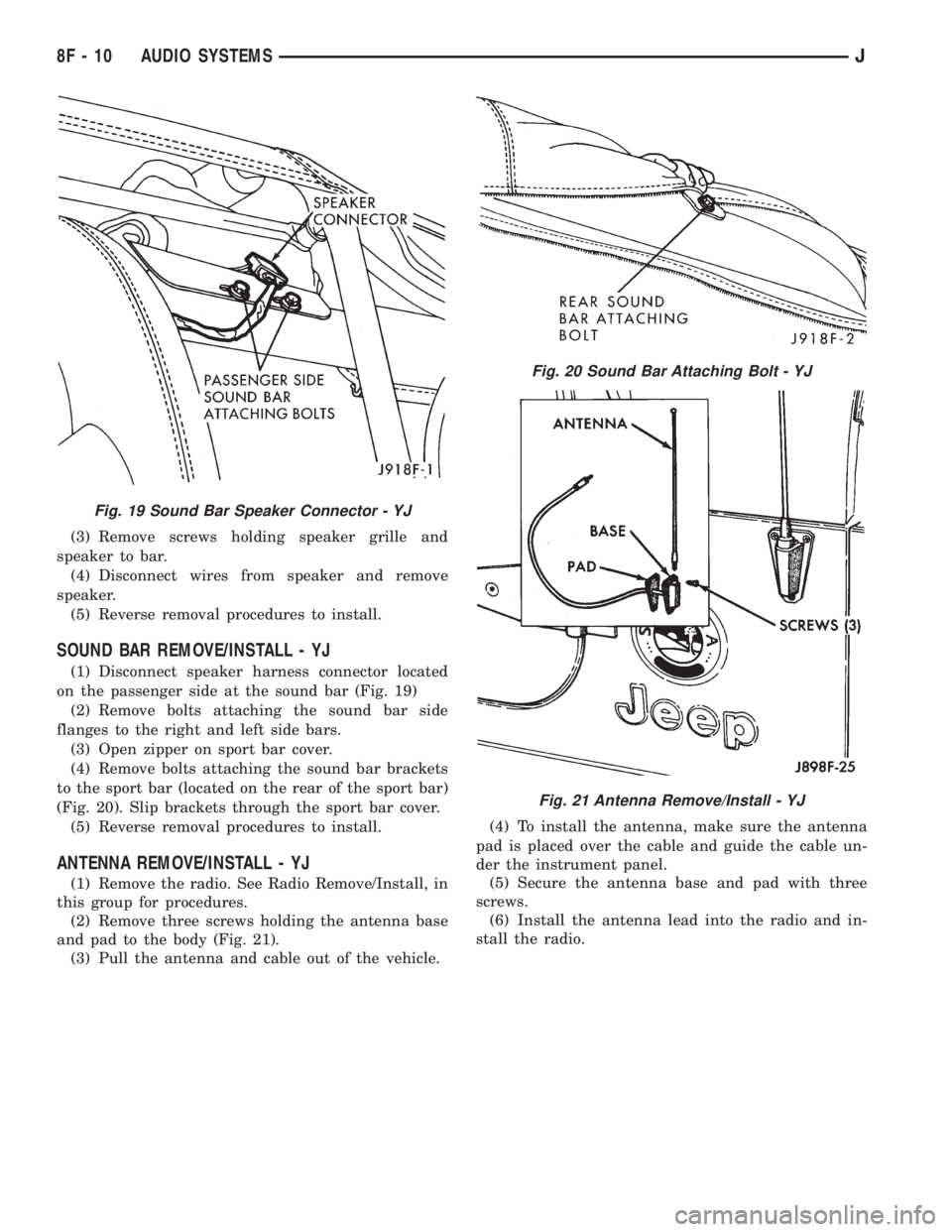
(1) Disconnect speaker harness connector located
on the passenger side at the sound bar (Fig. 19)
(2) Remove bolts attaching the sound bar side
flanges to the right and left side bars.
(3) Open zipper on sport bar cover.
(4) Remove bolts attaching the sound bar brackets
to the sport bar (located on the rear of the sport bar)
(Fig. 20). Slip brackets through the sport bar cover.
(5) Reverse removal procedures to install.
ANTENNA REMOVE/INSTALL - YJ
(1) Remove the radio. See Radio Remove/Install, in
this group for procedures.
(2) Remove three screws holding the antenna base
and pad to the body (Fig. 21).
(3) Pull the antenna and cable out of the vehicle.(4) To install the antenna, make sure the antenna
pad is placed over the cable and guide the cable un-
der the instrument panel.
(5) Secure the antenna base and pad with three
screws.
(6) Install the antenna lead into the radio and in-
stall the radio.
Fig. 19 Sound Bar Speaker Connector - YJ
Fig. 20 Sound Bar Attaching Bolt - YJ
Fig. 21 Antenna Remove/Install - YJ
8F - 10 AUDIO SYSTEMSJ
Page 654 of 2158
AUDIO SYSTEM
RADIO
When the ignition switch is in the ACCESSORY or
RUN position, it connects circuit A1 from fuse 6 in the
Power Distribution Center (PDC) to circuit A48. Cir-
cuit A48 powers circuit F85 through fuse 2 in the fuse
block. Circuit F85 powers the radio.
Circuit Z1 provides ground for the radio. The an-
tenna connects to the rear of the radio.
RADIO MEMORY
Circuit M1 from the Ignition Off Draw (IOD) fuse
(fuse 9) in the fuse block supplies power for the radio
memory. The IOD fuse is removed during vehicle
shipping to prevent excessive battery draw.
Circuit A6 from fuse 16 in the Power Distribution
Center (PDC) supplies voltage to fuse 9. Circuit A7
from fuse 3 in the PDC powers circuit A6 through
fuse 16. Circuits A6, A7 and M1 are HOT at all times.
RADIO ILLUMINATION
Circuit E2 supplies battery voltage to the radio
illumination lamps when the headlamps or parking
lamps are on and the dimmer switch is in the LOW or
ON positions.
Circuit X5 supplies battery voltage for the radio
clock and station frequency display. Circuit X5 origi-
nates at the radio illumination relay and is fed by
either circuit F85 or circuit E2 depending on the
switch position inside the relay.
When the headlamps and parking lamps are off, the
radio illumination relay is in its normal At Rest posi-
tion. In the At Rest position, the relay connects circuit
F85 from fuse 2 in the fuse block to circuit X5.
When the headlamps or parking lamps are on, cir-
cuit L90 from the headlamp switch supplies battery
voltage to the coil side of the radio illumination relay.
Circuit Z1 provides ground for the coil side of the
relay.
When voltage is present on circuit L90, the radio
illumination relay switches from its At Rest position
to connect circuit E2 to circuit X5.
SPEAKERS
There are 3 different radio packages. The standard
radio package includes 2 speakers; one in each front
door. The four speaker system uses speakers in each
front door plus speakers in the rear sound bar. The six
speaker system has the front door speakers, sound bar
speakers and two speakers in the instrument panel.
BASE RADIO
Vehicles with the base radio have a jumper between
the radio and the instrument panel connectors. The
jumper simulates rear speaker load.Circuit X53 feeds the speaker in the left front door.
Circuit X55 is the return from the speaker to the
radio.
Circuit X54 feeds the right front door speaker. Cir-
cuit X56 is the return from the speaker to the radio.
FOUR SPEAKER SYSTEM
Circuit X53 feeds the speaker in the left front door.
Circuit X55 is the return from the speaker to the
radio.
Circuit X54 feeds the right front door speaker. Cir-
cuit X56 is the return from the speaker to the radio.
Circuit X51 feeds the left rear speaker. Circuit X57
is the return from the speaker to the radio.
Circuit X52 feeds the right rear speaker. Circuit
X58 is the return from the speaker to the radio.
SIX SPEAKER SYSTEM
Circuit X53 feeds the left speaker in the instrument
panel. The X53 circuit is double crimped at the in-
strument panel left speaker and branches to the left
front door speaker. Circuit X55 is the return to the
radio from the instrument panel left speaker and left
front door speaker. Circuit X55 is double crimped at
the instrument panel left speaker.
Circuit X54 feeds the right speaker in the instru-
ment panel. The X54 circuit is double crimped at the
instrument panel right speaker and branches to the
right front door speaker. Circuit X56 is the return to
the radio from the instrument panel left speaker and
left front door speaker. Circuit X56 is double crimped
at the instrument panel left speaker.
Circuit X51 feeds the left rear speaker. Circuit X57
is the return from the speaker to the radio.
Circuit X52 feeds the right rear speaker. Circuit
X58 is the return from the speaker to the radio.
DIAGRAM INDEX
Component Page
Fuse Block...........................8W-47-2, 3
Headlamp Switch.........................8W-47-2
Ignition Switch..........................8W-47-2
LCD Relay.............................8W-47-3
Power Distribution Center..................8W-47-2, 3
Radio............................8W-47-2 thru 7
Speakers (Six Speaker System)..............8W-47-4, 5
Speakers (Four Speaker System).............8W-47-6, 7
J8W-47 AUDIO SYSTEMÐXJ VEHICLES 8W -47 - 1
Page 923 of 2158
RADIO
RADIO
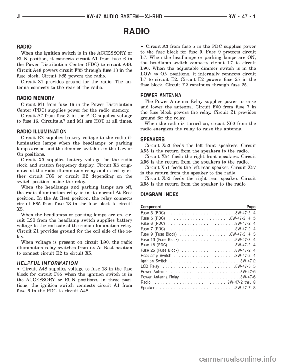
When the ignition switch is in the ACCESSORY or
RUN position, it connects circuit A1 from fuse 6 in
the Power Distribution Center (PDC) to circuit A48.
Circuit A48 powers circuit F85 through fuse 13 in the
fuse block. Circuit F85 powers the radio.
Circuit Z1 provides ground for the radio. The an-
tenna connects to the rear of the radio.
RADIO MEMORY
Circuit M1 from fuse 16 in the Power Distribution
Center (PDC) supplies power for the radio memory.
Circuit A7 from fuse 3 in the PDC supplies voltage
to fuse 16. Circuits A7 and M1 are HOT at all times.
RADIO ILLUMINATION
Circuit E2 supplies battery voltage to the radio il-
lumination lamps when the headlamps or parking
lamps are on and the dimmer switch is in the Low or
On positions.
Circuit X5 supplies battery voltage for the radio
clock and station frequency display. Circuit X5 origi-
nates at the radio illumination relay and is fed by ei-
ther circuit F85 or circuit E2 depending on the
switch position inside the relay.
When the headlamps and parking lamps are off,
the radio illumination relay is in its normal At Rest
position. In the At Rest position, the relay connects
circuit F85 from fuse 13 in the fuse block to circuit
X5.
When the headlamps or parking lamps are on, cir-
cuit L90 from the headlamp switch supplies battery
voltage to the coil side of the radio illumination relay.
Circuit Z1 provides ground for the coil side of the re-
lay.
When voltage is present on circuit L90, the radio
illumination relay switches from its At Rest position
to connect circuit E2 to circuit X5.
HELPFUL INFORMATION
²Circuit A48 supplies voltage to fuse 13 in the fuse
block for circuit F85 when the ignition switch is in
the ACCESSORY or RUN positions. In these posi-
tions, the ignition switch connects circuit A1 from
fuse 6 in the PDC to circuit A48.²Circuit A3 from fuse 5 in the PDC supplies power
to the fuse block for fuse 9. Fuse 9 protects circuit
L7. When the headlamps or parking lamps are ON,
the headlamp switch connects circuit L7 to circuit
L90. When the adjustable dimmer switch is in the
LOW to ON positions, it internally connects circuit
L7 to circuit E2. Circuit E2 powers fuse 25 in the
fuse block. Circuit E2 continues through fuse 25.
POWER ANTENNA
The Power Antenna Relay supplies power to raise
and lower the antenna. Circuit F60 from fuse 7 in
the fuse block powers the relay. Circuit Z1 provides
ground for the relay.
When the radio is turned on, circuit X60 from the
radio energizes the relay to raise the antenna.
SPEAKERS
Circuit X53 feeds the left front speakers. Circuit
X55 is the return from the speakers to the radio.
Circuit X54 feeds the right front speakers. Circuit
X56 is the return from the speakers to the radio.
Circuit X51 feeds the left rear speaker. Circuit X57
is the return from the speaker to the radio.
Circuit X52 feeds the right rear speaker. Circuit
X58 is the return from the speaker to the radio.
DIAGRAM INDEX
Component Page
Fuse 3 (PDC).........................8W-47-2, 4
Fuse 5 (PDC).......................8W-47-2, 4, 5
Fuse 6 (PDC).........................8W-47-2, 4
Fuse 7 (PDC).........................8W-47-2, 4
Fuse 9 (Fuse Block)...................8W-47-2, 4, 5
Fuse 13 (Fuse Block)....................8W-47-2, 4
Fuse 16 (PDC)........................8W-47-2, 4
Fuse 25 (Fuse Block)....................8W-47-2, 4
Headlamp Switch.......................8W-47-2, 4
Ignition Switch..........................8W-47-2
LCD Relay...........................8W-47-3, 5
Power Antenna..........................8W-47-6
Power Antenna Relay......................8W-47-6
Radio...........................8W-47-2 thru 8
Speakers............................8W-47-7, 8
J8W-47 AUDIO SYSTEMÐXJ-RHD 8W - 47 - 1
Page 1085 of 2158
SPLICE LOCATIONS
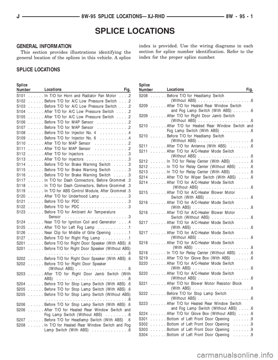
GENERAL INFORMATION
This section provides illustrations identifying the
general location of the splices in this vehicle. A spliceindex is provided. Use the wiring diagrams in each
section for splice number identification. Refer to the
index for the proper splice number.
SPLICE LOCATIONS
Splice
NumberLocations Fig.
S101......InT/OforHorn and Radiator Fan Motor....2
S102......Before T/O for A/C Low Pressure Switch....2
S103......Before T/O for A/C Low Pressure Switch....2
S104......After T/O for A/C Low Pressure Switch.....2
S105......After T/O for A/C Low Pressure Switch.....2
S106......Before T/O for MAP Sensor............2
S107......Before T/O for MAP Sensor............2
S108......Before T/O for Injector No. 4...........4
S109......Before T/O for Injector No. 6...........4
S110......After T/O for MAP Sensor.............2
S111......After T/O for MAP Sensor.............2
S112......After T/O for Injectors................3
S113......After T/O for Injectors................3
S114......Before T/O for Brake Warning Switch......3
S115......Before T/O for Brake Warning Switch......3
S116......Before T/O for Brake Warning Switch......3
S117......InT/OforDash Connectors, Before Grommet .3
S118......InT/OforDash Connectors, Before Grommet .3
S119......InT/OforABSControl Module, After Grommet .5
S120......After T/O for Underhood Lamp..........3
S121......Before T/O for PDC..................3
S122......Before T/O for PDC..................3
S123......Before T/O for Ambient Air Temperature
Sensor........................3
S124......Near T/O for Ignition Coil and Generator....4
S125......After T/O for Left Fog Lamp............1
S126......Near Clip for Middle of Gille Opening......1
S127......Before T/O for Right Fog Lamp..........1
S201......Before T/O for Right Door Speaker (With ABS) .6
S201......Before T/O for Right Door Speaker (Without ABS)
...............................6
S202......Before T/O for Right Door Speaker (With ABS) .6
S202......Before T/O for Right Door Speaker
(Without ABS)....................6
S203......After T/O for Right Door Jamb Switch (With
ABS)...........................6
S204......Before T/O for Stop Lamp Switch (With ABS) .6
S205......Before T/O for Stop Lamp Switch (With ABS) .6
S205......Before T/O for Stop Lamp Switch (Without ABS)
...............................6
S206......Before T/O for Stop Lamp Switch (With ABS) .6
S206......After T/O for Heated Rear Window Switch and
Fog Lamp Switch (Without ABS).........6
S207......Before T/O for Headlamp Switch (With ABS) .6
S208......InT/OforHeated Rear Window Switch and Fog
Lamp Switch (With ABS)..............6Splice
NumberLocations Fig.
S208......Before T/O for Headlamp Switch
(Without ABS)....................6
S209......After T/O for Heated Rear Window Switch
and Fog Lamp Switch (With ABS).......6
S209......After T/O for Right Door Jamb Switch
(Without ABS)....................6
S210......After T/O for Heated Rear Window Switch and
Fog Lamp Switch (With ABS)...........6
S210......Before T/O for Headlamp Switch
(Without ABS)....................6
S211......After T/O for Antenna (With ABS)........6
S211......After T/O for A/C-Heater Mode Switch
(Without ABS)....................6
S212......InT/OforRelay Center (With ABS).......6
S212......InT/OforRelay Center (Without ABS).....6
S213......InT/OforRelay Center (With ABS).......6
S214......After T/O for Wiper Switch (With ABS).....6
S214......After T/O for A/C-Heater Mode Switch
(Without ABS)...................6
S215......After T/O for A/C-Heater Blower Motor
Switch (With ABS).................6
S216......After T/O for A/C-Heater Mode Switch
(With ABS)......................6
S216......After T/O for A/C-Heater Blower Motor
Switch (Without ABS)...............6
S217......After T/O for A/C-Heater Mode Switch
(With ABS)......................6
S217......After T/O for A/C-Heater Mode Switch
(Without ABS)....................6
S218......After T/O for A/C-Heater Mode Switch
(With ABS).....................6
S218......InT/OforRelay Center (Without ABS).....6
S219......After T/O for Glove Box (With ABS).......6
S220......After T/O for A/C-Heater Mode Switch
(With ABS)......................6
S220......After T/O for A/C-Heater Mode Switch
(Without ABS)....................6
S221......After T/O for Blower Motor Resistor Block
(With ABS)......................6
S222......Before T/O for Stop Lamp Switch
(Without ABS)....................6
S223......After T/O for Heated Rear Window Switch
and Fog Lamp Switch (Without ABS).....6
S224......After T/O for Glove Box (Without ABS).....6
S301......Bottom of Left Front Door Opening.......9
S302......Bottom of Left Front Door Opening.......9
S303......Bottom of Left Front Door Opening.......9
S304......Bottom of Left Front Door Opening.......9
J8W-95 SPLICE LOCATIONSÐXJ-RHD 8W - 95 - 1