sensor JEEP YJ 1995 Service And Repair Manual
[x] Cancel search | Manufacturer: JEEP, Model Year: 1995, Model line: YJ, Model: JEEP YJ 1995Pages: 2158, PDF Size: 81.9 MB
Page 1761 of 2158
TORQUE CONVERTER STATOR CLUTCH
INSPECTION
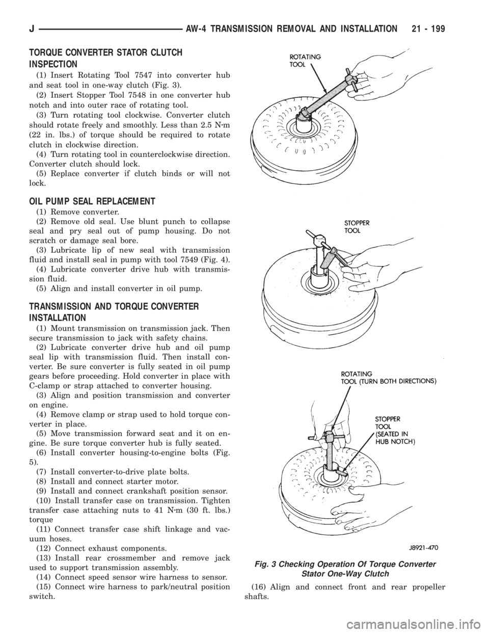
(1) Insert Rotating Tool 7547 into converter hub
and seat tool in one-way clutch (Fig. 3).
(2) Insert Stopper Tool 7548 in one converter hub
notch and into outer race of rotating tool.
(3) Turn rotating tool clockwise. Converter clutch
should rotate freely and smoothly. Less than 2.5 Nzm
(22 in. lbs.) of torque should be required to rotate
clutch in clockwise direction.
(4) Turn rotating tool in counterclockwise direction.
Converter clutch should lock.
(5) Replace converter if clutch binds or will not
lock.
OIL PUMP SEAL REPLACEMENT
(1) Remove converter.
(2) Remove old seal. Use blunt punch to collapse
seal and pry seal out of pump housing. Do not
scratch or damage seal bore.
(3) Lubricate lip of new seal with transmission
fluid and install seal in pump with tool 7549 (Fig. 4).
(4) Lubricate converter drive hub with transmis-
sion fluid.
(5) Align and install converter in oil pump.
TRANSMISSION AND TORQUE CONVERTER
INSTALLATION
(1) Mount transmission on transmission jack. Then
secure transmission to jack with safety chains.
(2) Lubricate converter drive hub and oil pump
seal lip with transmission fluid. Then install con-
verter. Be sure converter is fully seated in oil pump
gears before proceeding. Hold converter in place with
C-clamp or strap attached to converter housing.
(3) Align and position transmission and converter
on engine.
(4) Remove clamp or strap used to hold torque con-
verter in place.
(5) Move transmission forward seat and it on en-
gine. Be sure torque converter hub is fully seated.
(6) Install converter housing-to-engine bolts (Fig.
5).
(7) Install converter-to-drive plate bolts.
(8) Install and connect starter motor.
(9) Install and connect crankshaft position sensor.
(10) Install transfer case on transmission. Tighten
transfer case attaching nuts to 41 Nzm (30 ft. lbs.)
torque
(11) Connect transfer case shift linkage and vac-
uum hoses.
(12) Connect exhaust components.
(13) Install rear crossmember and remove jack
used to support transmission assembly.
(14) Connect speed sensor wire harness to sensor.
(15) Connect wire harness to park/neutral position
switch.(16) Align and connect front and rear propeller
shafts.
Fig. 3 Checking Operation Of Torque Converter
Stator One-Way Clutch
JAW-4 TRANSMISSION REMOVAL AND INSTALLATION 21 - 199
Page 1763 of 2158
AW-4 TRANSMISSION OVERHAUL
INDEX
page page
Cleaning and Inspection................... 214
Direct Clutch Overhaul.................... 228
First-Reverse Brake Piston and Transmission Case
Overhaul............................. 247
Forward Clutch Overhaul................... 232
Front Planetary Gear Overhaul.............. 237
Manual Valve Shaft Overhaul............... 215
Oil Pump Overhaul....................... 216
Overdrive Planetary Gear and Clutch Overhaul . . 218Overdrive Support Overhaul................ 226
Overhaul Service Tools.................... 201
Rear Planetary, No. 2 One-Way Clutch and Output
Shaft Overhaul......................... 244
Second Brake Overhaul................... 241
Sun Gear and No. 1 One-Way Clutch Overhaul . . 238
Transmission Assembly and Adjustment........ 265
Transmission Disassembly................. 201
Transmission Valve Body Overhaul........... 250
OVERHAUL SERVICE TOOLS
The special tools needed to overhaul the AW-4
transmission are provided in Tool Kit 6294. However,
Pressure Test Port Adapter 7554 is not included in
this kit and must be ordered separately. The over-
haul tool kit and test port adapter are available
through the parts division and dealer special tool
program.
TRANSMISSION DISASSEMBLY
(1) Remove torque converter.
(2) Remove lower half of filler tube if not previ-
ously removed.
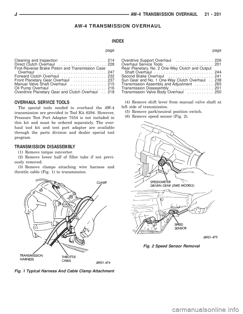
(3) Remove clamps attaching wire harness and
throttle cable (Fig. 1) to transmission.(4) Remove shift lever from manual valve shaft at
left side of transmission.
(5) Remove park/neutral position switch.
(6) Remove speed sensor (Fig. 2).
Fig. 1 Typical Harness And Cable Clamp Attachment
Fig. 2 Speed Sensor Removal
JAW-4 TRANSMISSION OVERHAUL 21 - 201
Page 1764 of 2158
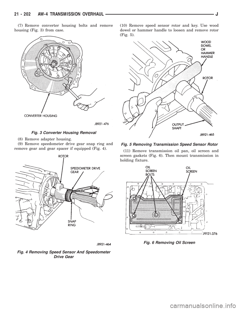
(7) Remove converter housing bolts and remove
housing (Fig. 3) from case.
(8) Remove adapter housing.
(9) Remove speedometer drive gear snap ring and
remove gear and gear spacer if equipped (Fig. 4).(10) Remove speed sensor rotor and key. Use wood
dowel or hammer handle to loosen and remove rotor
(Fig. 5).
(11) Remove transmission oil pan, oil screen and
screen gaskets (Fig. 6). Then mount transmission in
holding fixture.
Fig. 3 Converter Housing Removal
Fig. 4 Removing Speed Sensor And Speedometer
Drive Gear
Fig. 5 Removing Transmission Speed Sensor Rotor
Fig. 6 Removing Oil Screen
21 - 202 AW-4 TRANSMISSION OVERHAULJ
Page 1842 of 2158
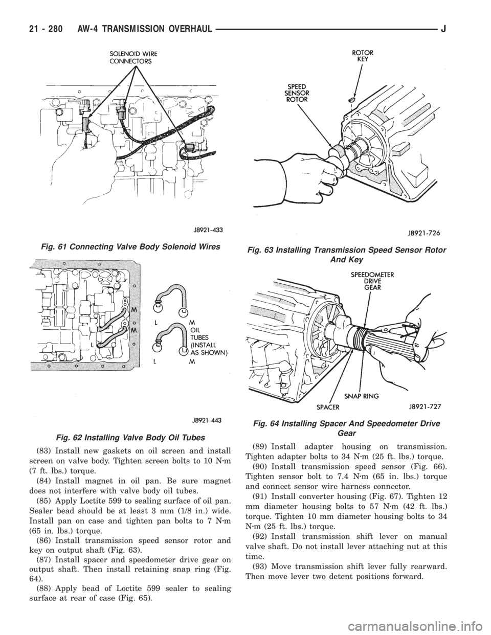
(83) Install new gaskets on oil screen and install
screen on valve body. Tighten screen bolts to 10 Nzm
(7 ft. lbs.) torque.
(84) Install magnet in oil pan. Be sure magnet
does not interfere with valve body oil tubes.
(85) Apply Loctite 599 to sealing surface of oil pan.
Sealer bead should be at least 3 mm (1/8 in.) wide.
Install pan on case and tighten pan bolts to 7 Nzm
(65 in. lbs.) torque.
(86) Install transmission speed sensor rotor and
key on output shaft (Fig. 63).
(87) Install spacer and speedometer drive gear on
output shaft. Then install retaining snap ring (Fig.
64).
(88) Apply bead of Loctite 599 sealer to sealing
surface at rear of case (Fig. 65).(89) Install adapter housing on transmission.
Tighten adapter bolts to 34 Nzm (25 ft. lbs.) torque.
(90) Install transmission speed sensor (Fig. 66).
Tighten sensor bolt to 7.4 Nzm (65 in. lbs.) torque
and connect sensor wire harness connector.
(91) Install converter housing (Fig. 67). Tighten 12
mm diameter housing bolts to 57 Nzm (42 ft. lbs.)
torque. Tighten 10 mm diameter housing bolts to 34
Nzm (25 ft. lbs.) torque.
(92) Install transmission shift lever on manual
valve shaft. Do not install lever attaching nut at this
time.
(93) Move transmission shift lever fully rearward.
Then move lever two detent positions forward.
Fig. 61 Connecting Valve Body Solenoid Wires
Fig. 62 Installing Valve Body Oil Tubes
Fig. 63 Installing Transmission Speed Sensor Rotor
And Key
Fig. 64 Installing Spacer And Speedometer Drive
Gear
21 - 280 AW-4 TRANSMISSION OVERHAULJ
Page 1843 of 2158
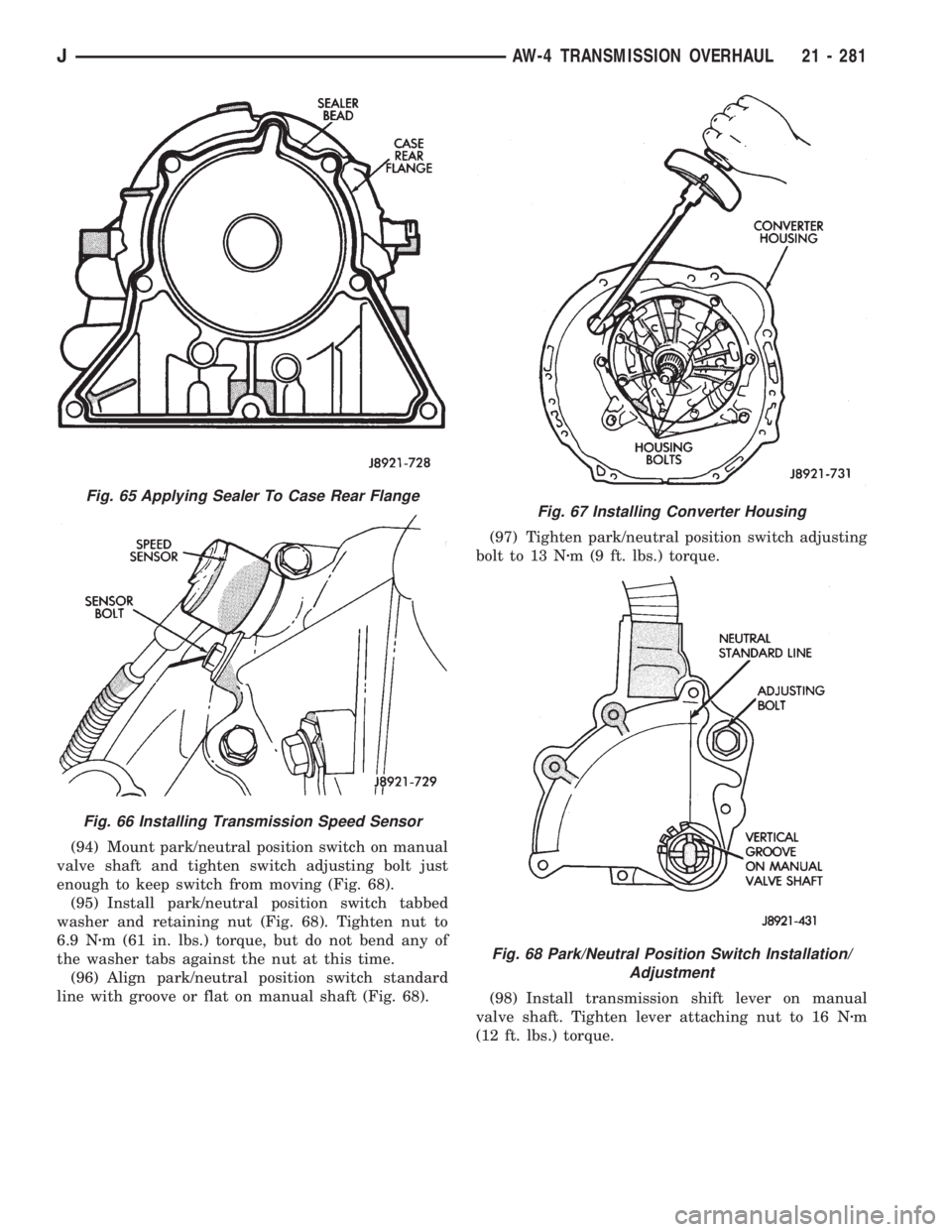
(94) Mount park/neutral position switch on manual
valve shaft and tighten switch adjusting bolt just
enough to keep switch from moving (Fig. 68).
(95) Install park/neutral position switch tabbed
washer and retaining nut (Fig. 68). Tighten nut to
6.9 Nzm (61 in. lbs.) torque, but do not bend any of
the washer tabs against the nut at this time.
(96) Align park/neutral position switch standard
line with groove or flat on manual shaft (Fig. 68).(97) Tighten park/neutral position switch adjusting
bolt to 13 Nzm (9 ft. lbs.) torque.
(98) Install transmission shift lever on manual
valve shaft. Tighten lever attaching nut to 16 Nzm
(12 ft. lbs.) torque.
Fig. 65 Applying Sealer To Case Rear Flange
Fig. 66 Installing Transmission Speed Sensor
Fig. 67 Installing Converter Housing
Fig. 68 Park/Neutral Position Switch Installation/
Adjustment
JAW-4 TRANSMISSION OVERHAUL 21 - 281
Page 1849 of 2158
(4) Lower vehicle.
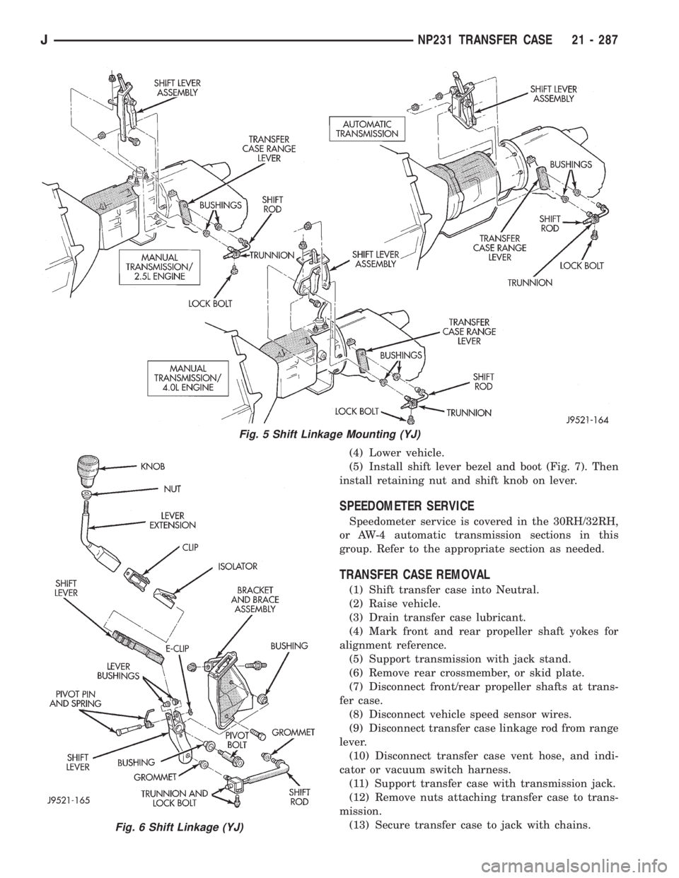
(5) Install shift lever bezel and boot (Fig. 7). Then
install retaining nut and shift knob on lever.
SPEEDOMETER SERVICE
Speedometer service is covered in the 30RH/32RH,
or AW-4 automatic transmission sections in this
group. Refer to the appropriate section as needed.
TRANSFER CASE REMOVAL
(1) Shift transfer case into Neutral.
(2) Raise vehicle.
(3) Drain transfer case lubricant.
(4) Mark front and rear propeller shaft yokes for
alignment reference.
(5) Support transmission with jack stand.
(6) Remove rear crossmember, or skid plate.
(7) Disconnect front/rear propeller shafts at trans-
fer case.
(8) Disconnect vehicle speed sensor wires.
(9) Disconnect transfer case linkage rod from range
lever.
(10) Disconnect transfer case vent hose, and indi-
cator or vacuum switch harness.
(11) Support transfer case with transmission jack.
(12) Remove nuts attaching transfer case to trans-
mission.
(13) Secure transfer case to jack with chains.
Fig. 5 Shift Linkage Mounting (YJ)
Fig. 6 Shift Linkage (YJ)
JNP231 TRANSFER CASE 21 - 287
Page 1850 of 2158
(14) Pull transfer case and jack rearward to disen-
gage transfer case.
(15) Remove transfer case from under vehicle.
(16) If transfer case was removed for overhaul, re-
move damper from rear retainer.
TRANSFER CASE INSTALLATION
(1) Mount transfer case on a transmission jack. Se-
cure transfer case to jack with chains.
(2) Position transfer case under vehicle.(3) Align transfer case and transmission shafts and
install transfer case on transmission.
(4) Install and tighten transfer case attaching nuts
to 35 Nzm (26 ft. lbs.) torque.
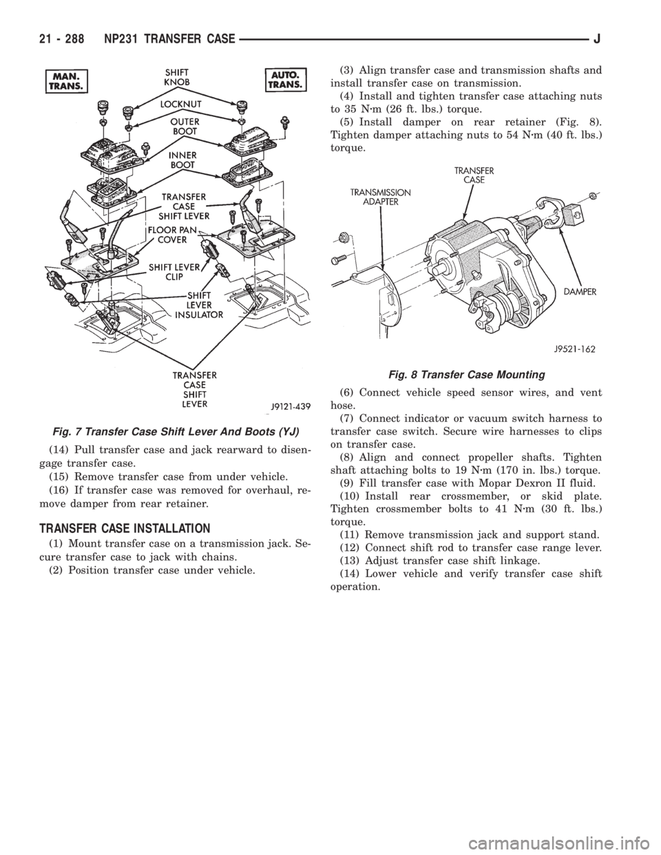
(5) Install damper on rear retainer (Fig. 8).
Tighten damper attaching nuts to 54 Nzm (40 ft. lbs.)
torque.
(6) Connect vehicle speed sensor wires, and vent
hose.
(7) Connect indicator or vacuum switch harness to
transfer case switch. Secure wire harnesses to clips
on transfer case.
(8) Align and connect propeller shafts. Tighten
shaft attaching bolts to 19 Nzm (170 in. lbs.) torque.
(9) Fill transfer case with Mopar Dexron II fluid.
(10) Install rear crossmember, or skid plate.
Tighten crossmember bolts to 41 Nzm (30 ft. lbs.)
torque.
(11) Remove transmission jack and support stand.
(12) Connect shift rod to transfer case range lever.
(13) Adjust transfer case shift linkage.
(14) Lower vehicle and verify transfer case shift
operation.
Fig. 7 Transfer Case Shift Lever And Boots (YJ)
Fig. 8 Transfer Case Mounting
21 - 288 NP231 TRANSFER CASEJ
Page 1871 of 2158
SHIFT LINKAGE ADJUSTMENT
(1) Shift transfer case into 4L position.
(2) Raise vehicle.
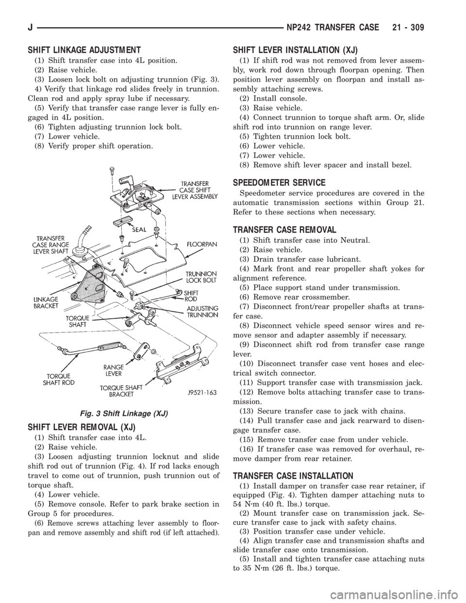
(3) Loosen lock bolt on adjusting trunnion (Fig. 3).
4) Verify that linkage rod slides freely in trunnion.
Clean rod and apply spray lube if necessary.
(5) Verify that transfer case range lever is fully en-
gaged in 4L position.
(6) Tighten adjusting trunnion lock bolt.
(7) Lower vehicle.
(8) Verify proper shift operation.
SHIFT LEVER REMOVAL (XJ)
(1) Shift transfer case into 4L.
(2) Raise vehicle.
(3) Loosen adjusting trunnion locknut and slide
shift rod out of trunnion (Fig. 4). If rod lacks enough
travel to come out of trunnion, push trunnion out of
torque shaft.
(4) Lower vehicle.
(5) Remove console. Refer to park brake section in
Group 5 for procedures.
(6) Remove screws attaching lever assembly to floor-
pan and remove assembly and shift rod (if left attached).
SHIFT LEVER INSTALLATION (XJ)
(1) If shift rod was not removed from lever assem-
bly, work rod down through floorpan opening. Then
position lever assembly on floorpan and install as-
sembly attaching screws.
(2) Install console.
(3) Raise vehicle.
(4) Connect trunnion to torque shaft arm. Or, slide
shift rod into trunnion on range lever.
(5) Tighten trunnion lock bolt.
(6) Lower vehicle.
(7) Lower vehicle.
(8) Remove shift lever spacer and install bezel.
SPEEDOMETER SERVICE
Speedometer service procedures are covered in the
automatic transmission sections within Group 21.
Refer to these sections when necessary.
TRANSFER CASE REMOVAL
(1) Shift transfer case into Neutral.
(2) Raise vehicle.
(3) Drain transfer case lubricant.
(4) Mark front and rear propeller shaft yokes for
alignment reference.
(5) Place support stand under transmission.
(6) Remove rear crossmember.
(7) Disconnect front/rear propeller shafts at trans-
fer case.
(8) Disconnect vehicle speed sensor wires and re-
move sensor and adapter assembly if necessary.
(9) Disconnect shift rod from transfer case range
lever.
(10) Disconnect transfer case vent hoses and elec-
trical switch connector.
(11) Support transfer case with transmission jack.
(12) Remove bolts attaching transfer case to trans-
mission.
(13) Secure transfer case to jack with chains.
(14) Pull transfer case and jack rearward to disen-
gage transfer case.
(15) Remove transfer case from under vehicle.
(16) If transfer case was removed for overhaul, re-
move damper from rear retainer.
TRANSFER CASE INSTALLATION
(1) Install damper on transfer case rear retainer, if
equipped (Fig. 4). Tighten damper attaching nuts to
54 Nzm (40 ft. lbs.) torque.
(2) Mount transfer case on transmission jack. Se-
cure transfer case to jack with safety chains.
(3) Position transfer case under vehicle.
(4) Align transfer case and transmission shafts and
slide transfer case onto transmission.
(5) Install and tighten transfer case attaching nuts
to 35 Nzm (26 ft. lbs.) torque.
Fig. 3 Shift Linkage (XJ)
JNP242 TRANSFER CASE 21 - 309
Page 1872 of 2158
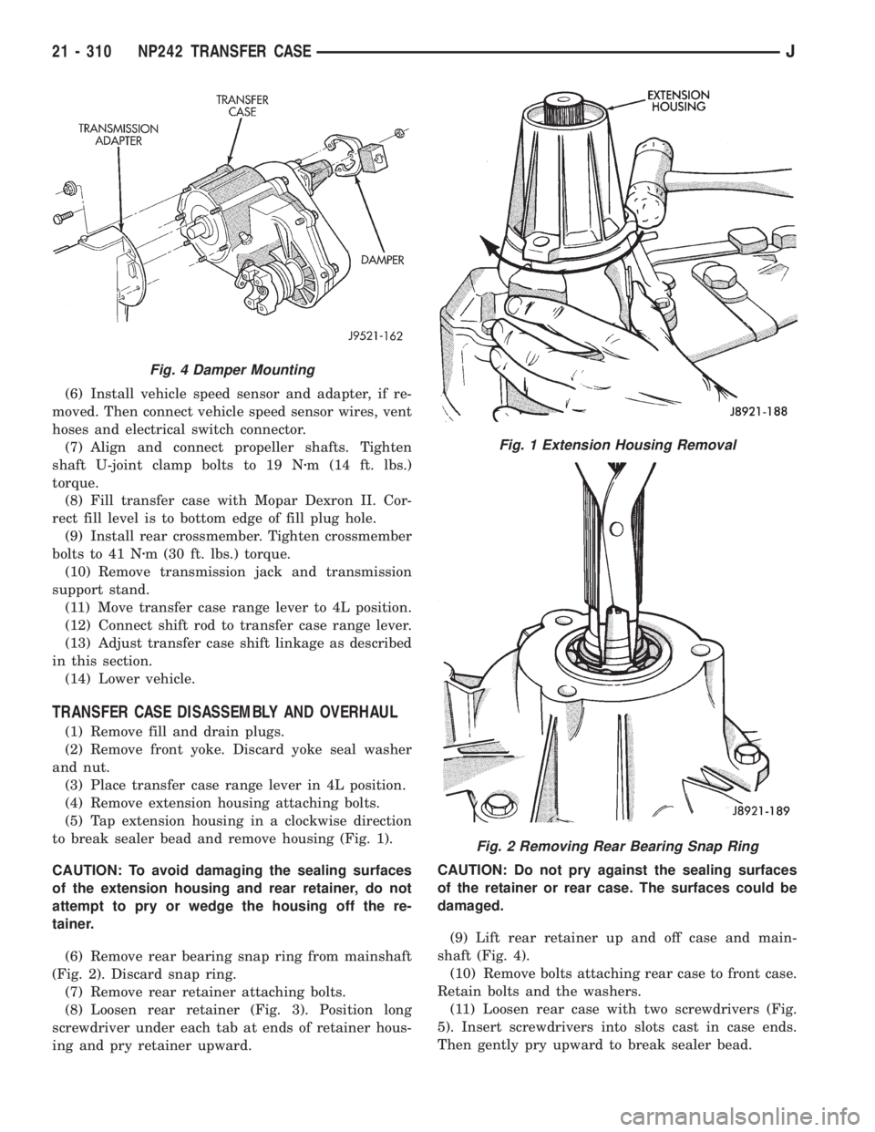
(6) Install vehicle speed sensor and adapter, if re-
moved. Then connect vehicle speed sensor wires, vent
hoses and electrical switch connector.
(7) Align and connect propeller shafts. Tighten
shaft U-joint clamp bolts to 19 Nzm (14 ft. lbs.)
torque.
(8) Fill transfer case with Mopar Dexron II. Cor-
rect fill level is to bottom edge of fill plug hole.
(9) Install rear crossmember. Tighten crossmember
bolts to 41 Nzm (30 ft. lbs.) torque.
(10) Remove transmission jack and transmission
support stand.
(11) Move transfer case range lever to 4L position.
(12) Connect shift rod to transfer case range lever.
(13) Adjust transfer case shift linkage as described
in this section.
(14) Lower vehicle.
TRANSFER CASE DISASSEMBLY AND OVERHAUL
(1) Remove fill and drain plugs.
(2) Remove front yoke. Discard yoke seal washer
and nut.
(3) Place transfer case range lever in 4L position.
(4) Remove extension housing attaching bolts.
(5) Tap extension housing in a clockwise direction
to break sealer bead and remove housing (Fig. 1).
CAUTION: To avoid damaging the sealing surfaces
of the extension housing and rear retainer, do not
attempt to pry or wedge the housing off the re-
tainer.
(6) Remove rear bearing snap ring from mainshaft
(Fig. 2). Discard snap ring.
(7) Remove rear retainer attaching bolts.
(8) Loosen rear retainer (Fig. 3). Position long
screwdriver under each tab at ends of retainer hous-
ing and pry retainer upward.CAUTION: Do not pry against the sealing surfaces
of the retainer or rear case. The surfaces could be
damaged.
(9) Lift rear retainer up and off case and main-
shaft (Fig. 4).
(10) Remove bolts attaching rear case to front case.
Retain bolts and the washers.
(11) Loosen rear case with two screwdrivers (Fig.
5). Insert screwdrivers into slots cast in case ends.
Then gently pry upward to break sealer bead.
Fig. 4 Damper Mounting
Fig. 1 Extension Housing Removal
Fig. 2 Removing Rear Bearing Snap Ring
21 - 310 NP242 TRANSFER CASEJ
Page 2096 of 2158
off switch for battery voltage. If no voltage is present
test pressure cut-off switch. If voltage is present go
to next step.
(5) With ohmmeter test harness connector ground
circuit for continuity to ground. If circuit is open, (no
continuity) repair ground circuit. If circuit test OK
and clutch does not engage refer to Powertrain Diag-
nostic Service Manual for A/C clutch circuit test.
AIR CONDITIONING CONTROLSÐYJ VEHICLES
The air conditioning circuit consists of 3 segments;
battery supply, blower motor and compressor clutch.
The 3 segments have a common connection point at
the blower switch.
The power supply circuit extends from the HTR/
FAN fuse to the blower switch. From the blower
switch, battery feed is routed to the blower motor
and compressor clutch circuit.
Refer to Group 8W Wiring Diagrams for wiring
schematic and terminals. Use volt ohmmeter to test
switches.
COMPRESSOR CLUTCH
The clutch assembly consists of a stationary elec-
tromagnetic coil, hub bearing pulley assembly, and
clutch plate. When the coil is energized the plate is
magnetically engaged with the pulley and turns the
compressor shaft.
COMPRESSOR CLUTCH TEST
(1) Unplug clutch coil connector.
(2) Connect jumper wire from battery positive post
to clutch coil connector. The clutch should engage, if
not leave jumper wire connected and go to next step.
(3) Connect jumper wire from clutch coil frame to
chassis ground. The clutch should engage, if not re-
pair clutch coil ground or replace coil.
A/C COMPRESSOR CLUTCH RELAY
The A/C compressor clutch relay controls the 12-
volt source to the A/C clutch. The relay is activated
when the PCM receives a A/C request signal. The
PCM then sends a ground signal to the relay. The re-
lay is activated and sends 12-volts to the clutch coil
which energizes the clutch. The relay is located in
the power distribution center.
COMPRESSOR CLUTCH RELAY TEST
For test procedure refer to Powertrain Diagnostic
Service Manual for A/C clutch relay circuit test.
LOW-PRESSURE HIGH-PRESSURE CUT-OFF
SWITCH
The pressure cut-off switch is located on the filter
drier and is wired in series with compressor clutch.
The switch interrupts the power to the compressorclutch circuit when the pressure drops to 193 kPa (28
psi) or increases above 3100 to 3375 kPa (450 to 490
psi).
PRESSURE CUT-OFF SWITCH TEST
(1) Turn ignition switch to RUN, A/C blower switch
to ON and control set to MAX.
(2) Unplug pressure cut-off switch connector and
test feed circuit from the thermostatic, should be bat-
tery voltage. If not, proceed to thermostatic control
tests.
(3) Test for continuity between the switch termi-
nals. If continuity is not present recover refrigerant
system, replace switch, evacuate and recharge sys-
tem.
THERMOSTATIC CONTROL
Cycling of the compressor and therefore the tem-
perature of the outlet air is regulated by the thermo-
static control. A thermal sensor extends from the
control to the evaporator housing. When the temper-
ature of the evaporator drops below the set tempera-
ture, the thermostatic control opens the clutch
circuit. The circuit remains open until evaporator
temperature rises above the set temperature.
THERMOSTATIC CONTROL TEST
(1) Turn ignition switch to RUN, A/C blower switch
to ON and thermostatic control set to MAX cool.
(2) Test thermostatic control feed terminal from
blower switch, should be battery voltage. If not re-
pair open from blower switch.
(3) Test thermostatic control output terminal to
pressure cut-out switch, should be battery voltage. If
not, replace thermostatic control.
BLOWER MOTOR SWITCH
The blower switch controls blower motor speed.
The blower motor segment consists of the 3 wires
from the blower switch to the motor. Through the
switch, the 3 wires connect the motor brushes to bat-
tery supply. When connected to battery feed, the sep-
arate brushes provide the 3 blower speeds LO, MED,
and HIGH.
BLOWER MOTOR SWITCH TEST
(1) Turn ignition to RUN position.
(2) Test battery side of fuse for battery voltage. If
not, repair open from ignition switch.
(3) Test A/C blower switch feed circuit from fuse
box should be battery voltage. If not, repair open
from fuse panel.
(4) Test A/C blower switch LO terminal with
blower switch in LO, should be battery voltage. If
not, replace switch.
(5) Test A/C blower switch MED terminal with
blower switch in MED, should be battery voltage. If
not, replace switch.
24 - 16 HEATING AND AIR CONDITIONINGJ