TRANSMISSION CONTROLS
UPSHIFT LAMP
On vehicles equipped with a manual transmission,
the PCM grounds the up-shift lamp on circuit K54.
Circuit K54 connects to cavity 54 of the PCM.
FOUR-WHEEL DRIVE (4WD) SWITCH
When the 4WD switch closes, circuit Z1 provides
ground for the 4WD indicator lamp in the instrument
cluster. Circuit F87 connects to the instrument clus-
ter and supplies battery voltage to the 4WD indicator
lamp. Circuit 107 connects the indicator lamp to the
4WD switch. Circuit 106 connects the lamp to the in-
strument cluster and circuit F87.
TRANSMISSION CONTROL MODULEÐ4.0L
ENGINE ONLY
Vehicles equipped with the 4.0L engine have elec-
tronically controlled solenoids in the automatic trans-
mission valve body.
The Transmission Control Module (TCM) receives
inputs from the Throttle Position Sensor (TPS) on
circuit K22 and the stop lamp switch on circuit K29.
Circuit K4 connects to the TCM to provide ground for
the TPS signal. The TCM receives the transmission
output speed sensor signal on circuit T505. Circuit
A14 from fuse 2 in the Power Distribution Center
supplies battery voltage to the TCM. Circuit Z12 pro-
vides ground for the TCM.
The TCM powers the S1 solenoid on circuit T510,
the S2 solenoid on circuit T509, and the S3 solenoid
on circuit T508. Circuit Z12 provides ground for the
S1, S2, and S3 solenoids.
TORQUE CONVERTER CLUTCH (TCC) SOLENOID
AND RELAYÐ2.5L ENGINE ONLY
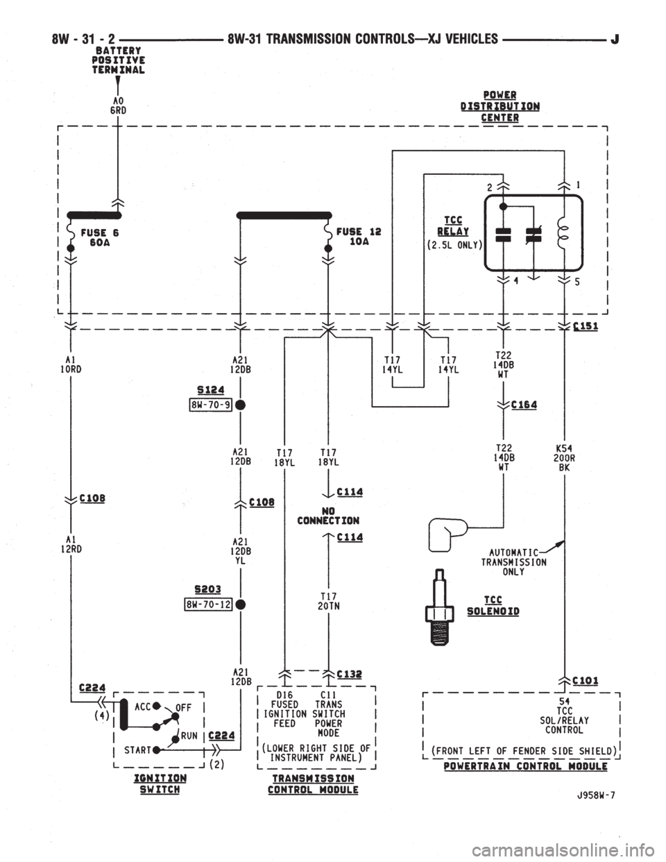
The TCC solenoid is only used on 2.5L engines
with the three-speed automatic transmissions. The
Powertrain Control Module (PCM) operates the TCC
solenoid by energizing the TCC relay.
Circuit T17 from fuse 12 in the Power Distribution
Center (PDC) supplies voltage to the coil and contact
sides of the TCC relay. When the PCM provides a
ground path on circuit K54 for the coil side of the re-
lay, the relay contacts close.
When the relay contacts close, they connect circuit
T17 with circuit T22. Circuit T22 supplies battery
voltage to the case grounded TCC solenoid. Circuit
K54 connects to PCM cavity 54.
HELPFUL INFORMATION
²In the RUN or START position, the ignition switch
connects circuit A1 from fuse 6 in the PDC to circuit
A21.
DIAGRAM INDEX
Component Page
4-WD Indicator Lamp......................8W-31-4
4-WD Indicator Switch.....................8W-31-4
Back-Up Lamp Switch.....................8W-31-3
Fuse 2 (PDC)...........................8W-31-4
Fuse 6 (PDC).........................8W-31-2, 3
Fuse 11 (PDC)..........................8W-31-3
Fuse 12 (PDC)..........................8W-31-2
Ignition Switch........................8W-31-2, 3
Powertrain Control Module..................8W-31-2
Park/Neutral Position Switch.................8W-31-3
TCC Relay.............................8W-31-2
TCC Solenoid...........................8W-31-2
Transmission Control Module.................8W-31-2
J8W-31 TRANSMISSION CONTROLSÐXJ VEHICLES 8W - 31 - 1
