JEEP YJ 1995 Service And Repair Manual
Manufacturer: JEEP, Model Year: 1995, Model line: YJ, Model: JEEP YJ 1995Pages: 2158, PDF Size: 81.9 MB
Page 611 of 2158
Page 612 of 2158
Page 613 of 2158
ANTI-LOCK BRAKES
INDEX
page page
ABS Power Relay.......................... 1
ABS Pump Motor Relay..................... 1
ABS Warning Lamp........................ 2
Acceleration Switch......................... 1
Brake Switch Input......................... 2
Data Link Connector........................ 2Diagram Index............................ 3
General Information........................ 1
Hydraulic Control Unit....................... 2
Pump Motor Speed Sensor................... 2
Wheel Speed Sensors...................... 1
GENERAL INFORMATION
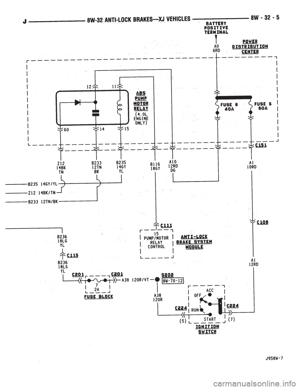
Three fuses supply power for the Anti-Lock Brake
System (ABS); fuses 8 and 10 in the Power Distribu-
tion Center (PDC) and fuse 7 in the fuse block. Fuses
8 and 10 in the PDC are connected directly to battery
voltage and are HOT all times. Fuse 7 in the fuse
block is HOT when the ignition switch is the RUN
Position.
In the RUN position, the ignition switch connects
circuit A1 from fuse 6 in the PDC with circuit A38.
Circuit A38 connects to a bus bar in the fuse block.
The bus bar feeds circuit B236 through fuse 7. Fuse 7
is a 2 amp fuse.
Circuit B236 connects to the coil side of the ABS
power relay and cavity 53 of the ABS control module.
Circuit Z1 provides ground for the ABS control mod-
ule. Circuit Z1 connects to cavities 1 and 19 of the
ABS control module.
Refer to group 5, Brakes for operational descrip-
tions of ABS system components.
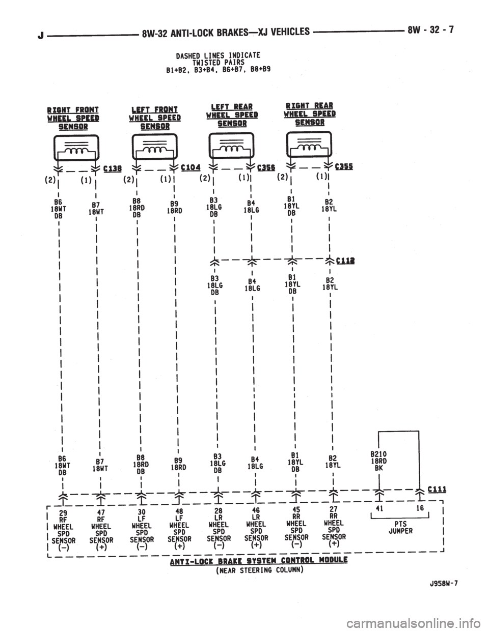
WHEEL SPEED SENSORS
The all wheel anti-lock system uses four wheel
speed sensors; one for each wheel. Each sensor con-
verts wheel speed into an electrical signal that it
transmits to the ABS control module. A pair of
twisted wires connect to each sensor to provide sig-
nals to the ABS control module.
Circuits B6 and B7 provide signals to ABS control
module from right front wheel speed sensor. Circuit
B6 which provides the LOW signal connects to cavity
29 of the ABS control module. Circuit B7 connects to
cavity 47 of the module and provides the HIGH sig-
nal.
Circuits B8 and B9 provide signals to ABS control
module from left front wheel speed sensor. Circuit B8,
which provides the LOW signal, connects to cavity 30
of the ABS control module. Circuit B9 connects to
cavity 48 of the module and provides the HIGH sig-
nal.
Circuits B1 and B2 provide signals to ABS control
module from right rear wheel speed sensor. Circuit
B1 which provides the LOW signal connects to cavity45 of the ABS control module. Circuit B2 connects to
cavity 27 of the module and provides the HIGH sig-
nal.
Circuits B4 and B3 provide signals to ABS control
module from left rear wheel speed sensor. Circuit B3,
which provides the LOW signal, connects to cavity 28
of the ABS control module. Circuit B4 connects to
cavity 46 of the module and provides the HIGH sig-
nal.
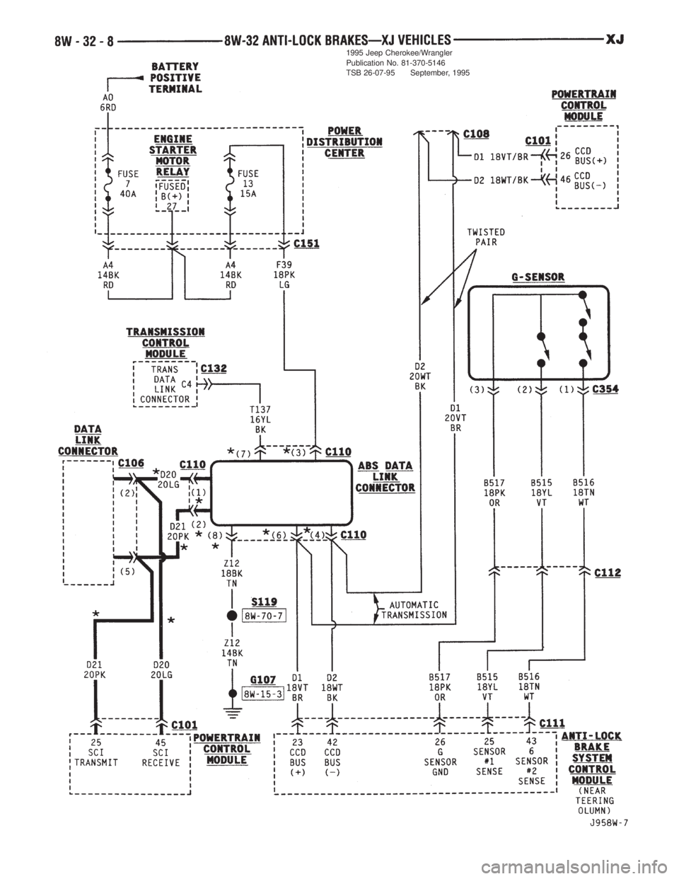
ACCELERATION SWITCH
During four-wheel drive operation, the acceleration
(G) switch provides deceleration data to the ABS con-
trol module. Refer to Group 5, Brakes for additional
information.
Circuits B515, B516, and B517 connect the accel-
eration sensor to the ABS control module. Circuits
B515 and B516 provide switch states while circuit
B517 provides ground. At the ABS control module
circuit B515 connects to cavity 25, circuit B516 con-
nects to cavity 43 and circuit B517 connects to cavity
26.
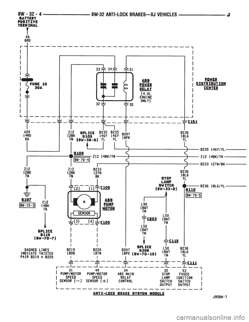
ABS POWER RELAY
The ABS power relay is located in the power distri-
bution center (PDC). When the ABS module grounds
the ABS power relay on circuit B207, the relay
switches to connect circuit A20 from PDC fuse 10 to
circuit B235. Circuit B236 from fuse 7 in the fuse
block splices to feed the coil side of the ABS power
relay. Circuit B207 connects to cavity 34 of the ABS
control module.
Circuit B235 is double crimped at the ABS power
relay. One branch of circuit B235 supplies power to
the coil side of the ABS pump motor relay. The other
branch of circuit B235 splices to cavities 3 and 33 of
the ABS control module and to the hydraulic control
unit.
ABS PUMP MOTOR RELAY
The ABS pump motor relay in the power distribu-
tion center (PDC) supplies voltage to the ABS pump
motor. When the ABS power relay energizes, circuit
B235 supplies battery voltage to the coil side of the
J8W-32 ANTI-LOCK BRAKESÐXJ VEHICLES 8W - 32 - 1
Page 614 of 2158
ABS pump motor relay. The ABS control module pro-
vides ground for the relay on circuit B116. Circuit
B116 connects to cavity 15 of the ABS control mod-
ule.
When the ABS pump motor energizes, it connects
circuit A10 from PDC fuse 8 to circuit B233. Circuit
B233 supplies battery voltage to the pump motor.
Circuit Z12 provides ground for the pump motor.
PUMP MOTOR SPEED SENSOR
The input from the pump motor speed sensor tells
the ABS control module that the pump is operating.
Circuits B219 and B220 from the control module con-
nect to the speed sensor.
BRAKE SWITCH INPUT
Circuit L50 from the stop lamp provides the brake
switch input to the ABS control module. When the
brake pedal is depressed, the stop lamp switch closes
to supply battery voltage from circuit L9 to circuit
L50. Circuit L50 connects to cavity 32 of the ABS
control module. Circuit L9 originates at fuse 4 in the
Power Distribution Center (PDC).
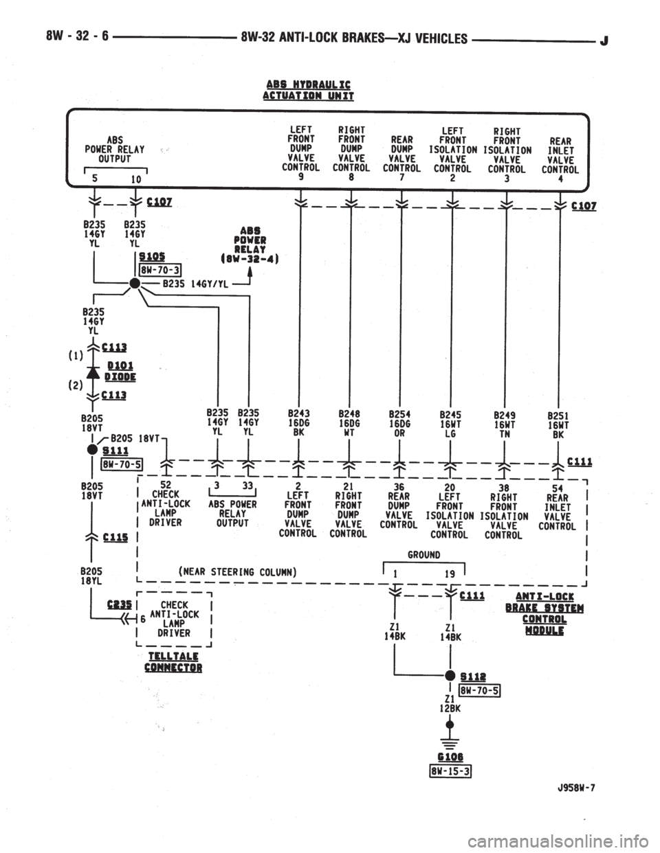
HYDRAULIC CONTROL UNIT
When the ABS power relay energizes, two branches
of circuit B235 splice to supply voltage to the isola-
tion and dump solenoids in the hydraulic control
unit. The hydraulic control unit contains three sepa-
rate isolation solenoids and three separate dump so-
lenoids. The ABS control module activates the decay
and isolation solenoids by providing separate ground
paths for each.
The ABS module provides a ground path for the
rear isolation solenoid on circuit B251. Circuit B251
connects to cavity 54 of the ABS control module.
For the right front isolation solenoid, the ABS mod-
ule provides a ground path on circuit B249. Circuit
B249 connects to cavity 38 of the ABS control mod-
ule.
On circuit B245, the ABS module provides ground
for the left front isolation solenoid. Circuit B245 con-
nects to cavity 20 of the ABS control module.
The ABS module provides a ground path for the
rear decay solenoid on circuit B254. Circuit B254
connects to cavity 36 of the ABS control module.For the right front decay solenoid, the ABS module
provides a ground path on circuit B248. Circuit B248
connects to cavity 21 of the ABS control module.
On circuit B243, the ABS module provides ground
for the left decay solenoid. Circuit B243 connects to
cavity 2 of the ABS control module.
ABS WARNING LAMP
Circuit F87 provides power for the ABS warning
lamp at the instrument cluster. Ground for the ABS
warning lamp is provided by either the ABS control
module or by the ABS power relay when the relay is
not energized. The ABS control module illuminates
the lamp by providing ground on circuit B205.
Circuit B205 splices to connect to circuit B235
through a diode. When the ABS power relay is not
energized, it connects circuit B235 to circuit Z12. The
ground path for the warning lamp is through the di-
ode to circuit B235, through the ABS power relay to
ground on circuit Z12.
The diode between circuit B205 and B235 prevents
voltage from flowing to the ABS control module when
the ABS power relay switches to supply power on cir-
cuit B235.
DATA LINK CONNECTOR
Circuit D1 from cavity 23 of the ABS control mod-
ule receives data from the DRB scan tool through the
data link connector. The ABS control module trans-
mits data to the scan tool through the connector on
circuit D2. Circuit D2 originates at cavity 42 of the
ABS control module.
Through the data link connector, circuit Z12 pro-
vides ground for the DRB scan tool.
Circuit A4 from fuse 10 in the Power Distribution
Center (PDC) supplies power to fuse 5 in the PDC.
Fuse 5 powers circuit F39 which supplies battery
voltage to the scan tool through the diagnostic con-
nector.
HELPFUL INFORMATION
²Check fuses 10 and 5 in the PDC.
²If the vehicle is equipped with an automatic trans-
mission, circuits D1 and D2 are double crimped at
the data link connector and connect to the Power-
train Control Module (PCM).
8W - 32 - 2 8W-32 ANTI-LOCK BRAKESÐXJ VEHICLESJ
Page 615 of 2158
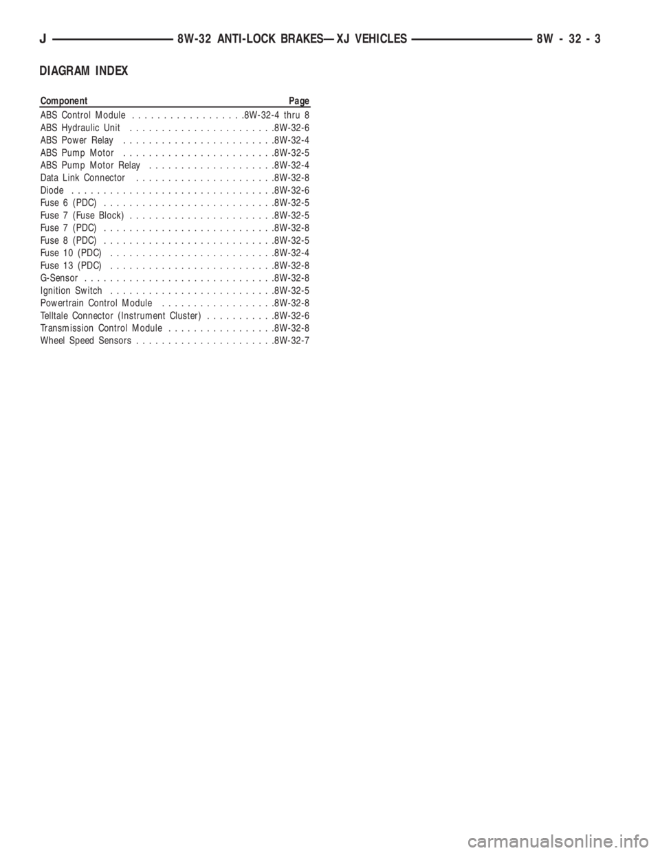
DIAGRAM INDEX
Component Page
ABS Control Module..................8W-32-4 thru 8
ABS Hydraulic Unit.......................8W-32-6
ABS Power Relay........................8W-32-4
ABS Pump Motor........................8W-32-5
ABS Pump Motor Relay....................8W-32-4
Data Link Connector......................8W-32-8
Diode................................8W-32-6
Fuse 6 (PDC)...........................8W-32-5
Fuse 7 (Fuse Block).......................8W-32-5
Fuse 7 (PDC)...........................8W-32-8
Fuse 8 (PDC)...........................8W-32-5
Fuse 10 (PDC)..........................8W-32-4
Fuse 13 (PDC)..........................8W-32-8
G-Sensor..............................8W-32-8
Ignition Switch..........................8W-32-5
Powertrain Control Module..................8W-32-8
Telltale Connector (Instrument Cluster)...........8W-32-6
Transmission Control Module.................8W-32-8
Wheel Speed Sensors......................8W-32-7
J8W-32 ANTI-LOCK BRAKESÐXJ VEHICLES 8W - 32 - 3
Page 616 of 2158
Page 617 of 2158
Page 618 of 2158
Page 619 of 2158
Page 620 of 2158
1995 Jeep Cherokee/Wrangler
Publication No. 81-370-5146
TSB 26-07-95 September, 1995