air bleeding JEEP YJ 1995 Service And Repair Manual
[x] Cancel search | Manufacturer: JEEP, Model Year: 1995, Model line: YJ, Model: JEEP YJ 1995Pages: 2158, PDF Size: 81.9 MB
Page 162 of 2158
BRAKE FLUIDÐBRAKE BLEEDINGÐBRAKELINES AND HOSES
INDEX
page page
Brake Bleeding (With ABS Brakes)............ 11
Brake Bleeding (With Standard Brakes)......... 11
Brake Bleeding Recommendations............ 10
Brake Fluid Contamination.................. 10Brake Fluid Level......................... 10
Brakeline Charts.......................... 12
Brakelines and Hoses...................... 12
Recommended Brake Fluid.................. 10
RECOMMENDED BRAKE FLUID
Recommended brake fluid for Jeep vehicles is Mo-
par brake fluid, or an equivalent fluid meeting SAE
J1703 and DOT 3 standards. The recommendation
applies to models with standard or ABS brakes.
Use new brake fluid to top off the master cyl-
inder or refill the system. Never use reclaimed
fluid, fluid not meeting the SAE/DOT standards
or fluid from an unsealed container. Do not use
fluid from any container that has been left
open for any length of time. Fluid in open con-
tainers can absorb moisture.
BRAKE FLUID LEVEL
Always clean the master cylinder reservoir and
cover or cap before adding fluid. This avoids having
dirt from the cap or reservoir exterior fall into the
fluid.
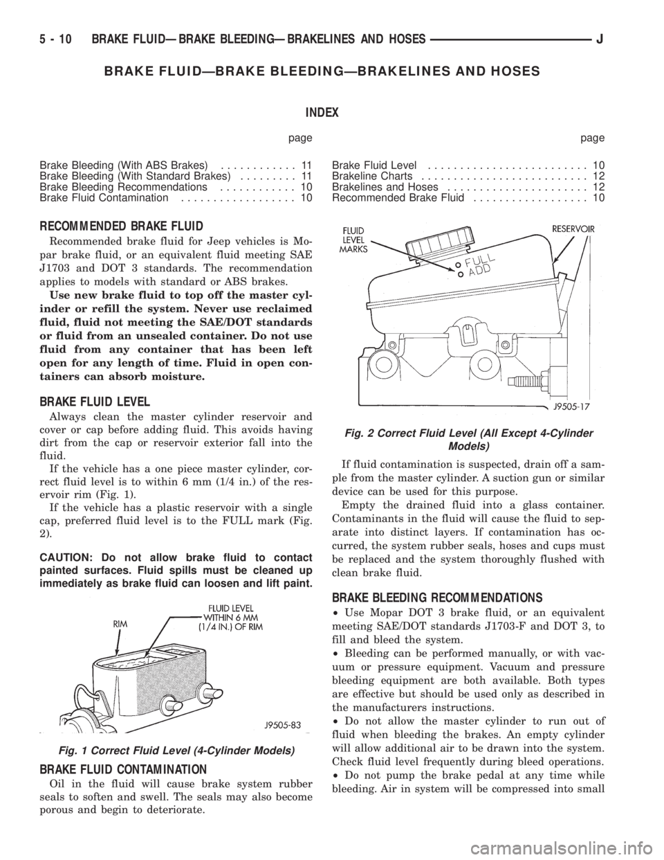
If the vehicle has a one piece master cylinder, cor-
rect fluid level is to within 6 mm (1/4 in.) of the res-
ervoir rim (Fig. 1).
If the vehicle has a plastic reservoir with a single
cap, preferred fluid level is to the FULL mark (Fig.
2).
CAUTION: Do not allow brake fluid to contact
painted surfaces. Fluid spills must be cleaned up
immediately as brake fluid can loosen and lift paint.
BRAKE FLUID CONTAMINATION
Oil in the fluid will cause brake system rubber
seals to soften and swell. The seals may also become
porous and begin to deteriorate.If fluid contamination is suspected, drain off a sam-
ple from the master cylinder. A suction gun or similar
device can be used for this purpose.
Empty the drained fluid into a glass container.
Contaminants in the fluid will cause the fluid to sep-
arate into distinct layers. If contamination has oc-
curred, the system rubber seals, hoses and cups must
be replaced and the system thoroughly flushed with
clean brake fluid.
BRAKE BLEEDING RECOMMENDATIONS
²Use Mopar DOT 3 brake fluid, or an equivalent
meeting SAE/DOT standards J1703-F and DOT 3, to
fill and bleed the system.
²Bleeding can be performed manually, or with vac-
uum or pressure equipment. Vacuum and pressure
bleeding equipment are both available. Both types
are effective but should be used only as described in
the manufacturers instructions.
²Do not allow the master cylinder to run out of
fluid when bleeding the brakes. An empty cylinder
will allow additional air to be drawn into the system.
Check fluid level frequently during bleed operations.
²Do not pump the brake pedal at any time while
bleeding. Air in system will be compressed into small
Fig. 1 Correct Fluid Level (4-Cylinder Models)
Fig. 2 Correct Fluid Level (All Except 4-Cylinder
Models)
5 - 10 BRAKE FLUIDÐBRAKE BLEEDINGÐBRAKELINES AND HOSESJ
Page 163 of 2158
bubbles that are distributed throughout the hydrau-
lic system. This will make extra bleeding operations
necessary.
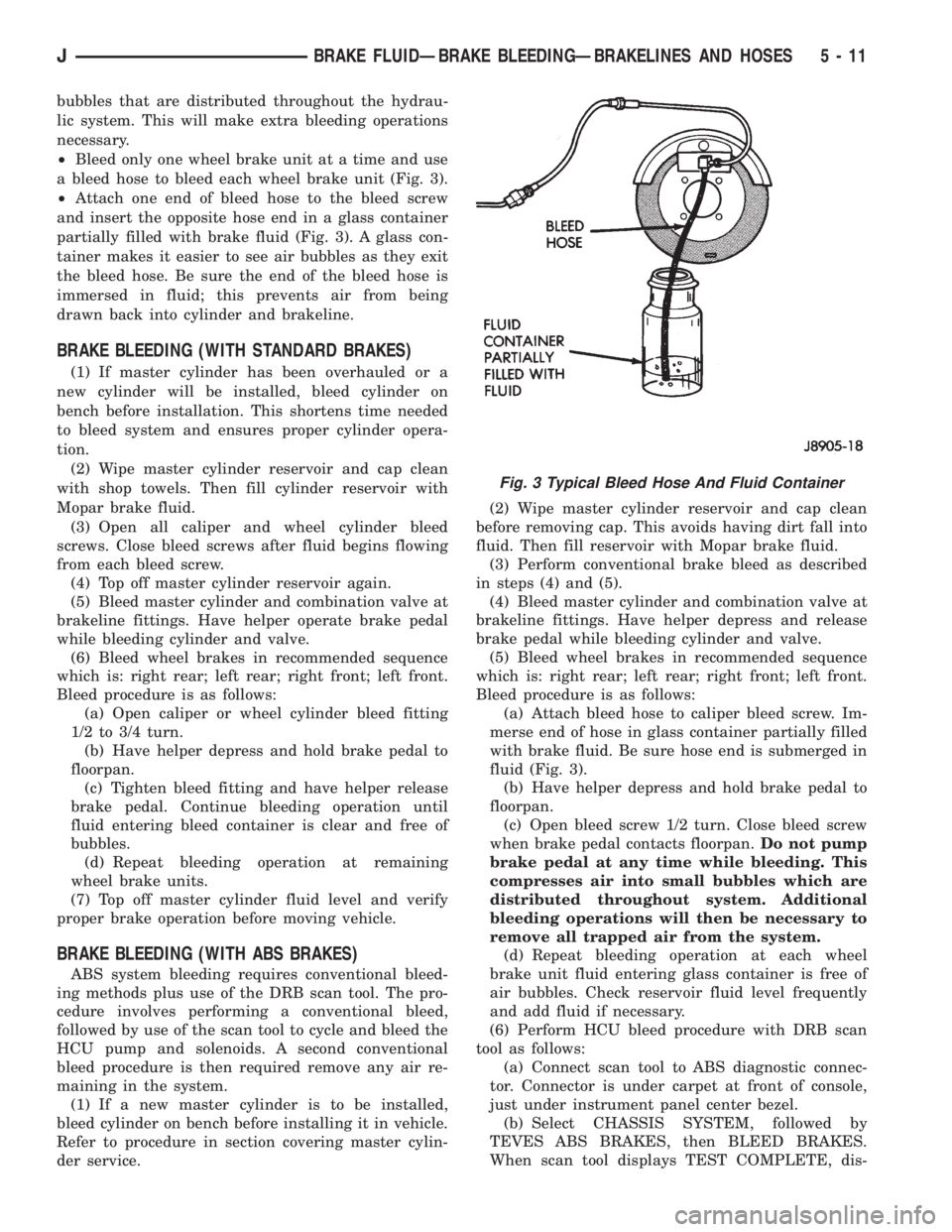
²Bleed only one wheel brake unit at a time and use
a bleed hose to bleed each wheel brake unit (Fig. 3).
²Attach one end of bleed hose to the bleed screw
and insert the opposite hose end in a glass container
partially filled with brake fluid (Fig. 3). A glass con-
tainer makes it easier to see air bubbles as they exit
the bleed hose. Be sure the end of the bleed hose is
immersed in fluid; this prevents air from being
drawn back into cylinder and brakeline.
BRAKE BLEEDING (WITH STANDARD BRAKES)
(1) If master cylinder has been overhauled or a
new cylinder will be installed, bleed cylinder on
bench before installation. This shortens time needed
to bleed system and ensures proper cylinder opera-
tion.
(2) Wipe master cylinder reservoir and cap clean
with shop towels. Then fill cylinder reservoir with
Mopar brake fluid.
(3) Open all caliper and wheel cylinder bleed
screws. Close bleed screws after fluid begins flowing
from each bleed screw.
(4) Top off master cylinder reservoir again.
(5) Bleed master cylinder and combination valve at
brakeline fittings. Have helper operate brake pedal
while bleeding cylinder and valve.
(6) Bleed wheel brakes in recommended sequence
which is: right rear; left rear; right front; left front.
Bleed procedure is as follows:
(a) Open caliper or wheel cylinder bleed fitting
1/2 to 3/4 turn.
(b) Have helper depress and hold brake pedal to
floorpan.
(c) Tighten bleed fitting and have helper release
brake pedal. Continue bleeding operation until
fluid entering bleed container is clear and free of
bubbles.
(d) Repeat bleeding operation at remaining
wheel brake units.
(7) Top off master cylinder fluid level and verify
proper brake operation before moving vehicle.
BRAKE BLEEDING (WITH ABS BRAKES)
ABS system bleeding requires conventional bleed-
ing methods plus use of the DRB scan tool. The pro-
cedure involves performing a conventional bleed,
followed by use of the scan tool to cycle and bleed the
HCU pump and solenoids. A second conventional
bleed procedure is then required remove any air re-
maining in the system.
(1) If a new master cylinder is to be installed,
bleed cylinder on bench before installing it in vehicle.
Refer to procedure in section covering master cylin-
der service.(2) Wipe master cylinder reservoir and cap clean
before removing cap. This avoids having dirt fall into
fluid. Then fill reservoir with Mopar brake fluid.
(3) Perform conventional brake bleed as described
in steps (4) and (5).
(4) Bleed master cylinder and combination valve at
brakeline fittings. Have helper depress and release
brake pedal while bleeding cylinder and valve.
(5) Bleed wheel brakes in recommended sequence
which is: right rear; left rear; right front; left front.
Bleed procedure is as follows:
(a) Attach bleed hose to caliper bleed screw. Im-
merse end of hose in glass container partially filled
with brake fluid. Be sure hose end is submerged in
fluid (Fig. 3).
(b) Have helper depress and hold brake pedal to
floorpan.
(c) Open bleed screw 1/2 turn. Close bleed screw
when brake pedal contacts floorpan.Do not pump
brake pedal at any time while bleeding. This
compresses air into small bubbles which are
distributed throughout system. Additional
bleeding operations will then be necessary to
remove all trapped air from the system.
(d) Repeat bleeding operation at each wheel
brake unit fluid entering glass container is free of
air bubbles. Check reservoir fluid level frequently
and add fluid if necessary.
(6) Perform HCU bleed procedure with DRB scan
tool as follows:
(a) Connect scan tool to ABS diagnostic connec-
tor. Connector is under carpet at front of console,
just under instrument panel center bezel.
(b) Select CHASSIS SYSTEM, followed by
TEVES ABS BRAKES, then BLEED BRAKES.
When scan tool displays TEST COMPLETE, dis-
Fig. 3 Typical Bleed Hose And Fluid Container
JBRAKE FLUIDÐBRAKE BLEEDINGÐBRAKELINES AND HOSES 5 - 11
Page 164 of 2158
connect scan tool and proceed to next step.
(7)Repeatconventional bleed procedure described
in steps (4) and (5).
(8) Top off master cylinder fluid level and verify
proper brake operation before moving vehicle.
BRAKELINES AND HOSES
Metal brakelines and rubber brake hoses should be
inspected periodically and replaced if damaged.
Rubber brake hoses should be replaced if cut,
cracked, swollen, or leaking. Rubber hoses must be
replaced as they are not repairable.
Steel brakelines should be inspected any time the
vehicle is in for normal maintenance. This is impor-
tant on high mileage vehicles. It is especially impor-
tant when the vehicle is operated on roads that are
salted during winter months.
Heavily rusted/corroded brake rotors, drums,
support plates, and brakelines should be
cleaned and carefully inspected. Heavy rust
buildup can hide severe damage to a compo-
nent. Severely rusted parts should be replaced
if condition is suspect.
BRAKELINE CHARTS
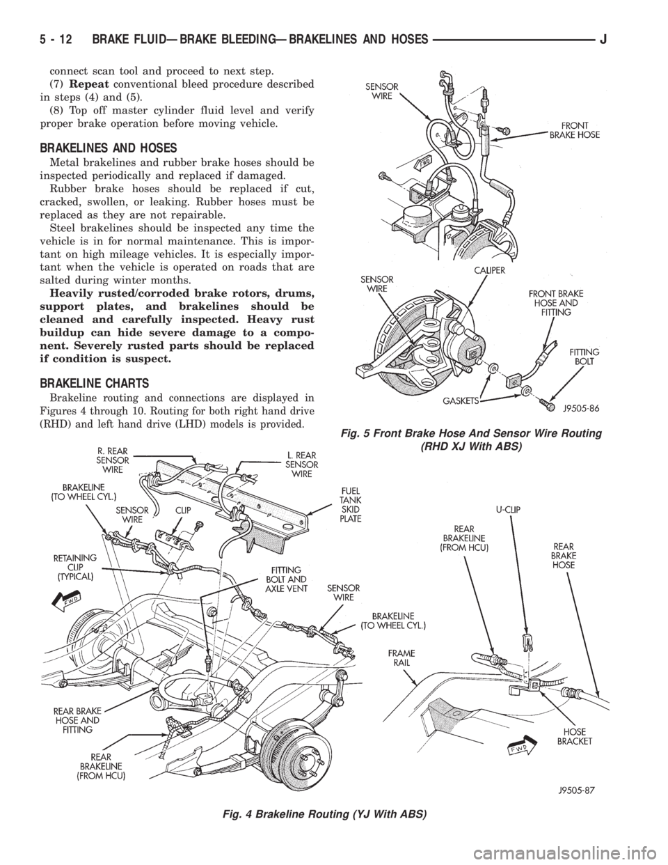
Brakeline routing and connections are displayed in
Figures 4 through 10. Routing for both right hand drive
(RHD) and left hand drive (LHD) models is provided.
Fig. 4 Brakeline Routing (YJ With ABS)
Fig. 5 Front Brake Hose And Sensor Wire Routing
(RHD XJ With ABS)
5 - 12 BRAKE FLUIDÐBRAKE BLEEDINGÐBRAKELINES AND HOSESJ
Page 167 of 2158
MASTER CYLINDERÐCOMBINATION VALVE
INDEX
page page
Combination Valve Replacement (Non-ABS)..... 16
General Service Information................. 15
Master Cylinder and Combination Valve Installation
(With ABS)............................. 20
Master Cylinder and Combination Valve Removal
(With ABS)............................. 17Master Cylinder Bench Bleeding.............. 21
Master Cylinder Installation (Non-ABS)......... 16
Master Cylinder Overhaul (4-Cylinder Models).... 16
Master Cylinder Removal (Non-ABS)........... 15
Reservoir Replacement (2-Piece Master Cylinder) . 19
GENERAL SERVICE INFORMATION
Master Cylinder
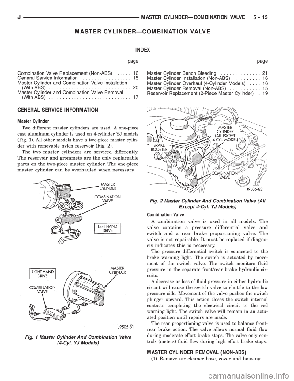
Two different master cylinders are used. A one-piece
cast aluminum cylinder is used on 4-cylinder YJ models
(Fig. 1). All other models have a two-piece master cylin-
der with removable nylon reservoir (Fig. 2).
The two master cylinders are serviced differently.
The reservoir and grommets are the only replaceable
parts on the two-piece master cylinder. The one-piece
master cylinder can be overhauled when necessary.
Combination Valve
A combination valve is used in all models. The
valve contains a pressure differential valve and
switch and a rear brake proportioning valve. The
valve is not repairable. It must be replaced if diagno-
sis indicates this is necessary.
The pressure differential switch is connected to the
brake warning light. The switch is actuated by move-
ment of the switch valve. The switch monitors fluid
pressure in the separate front/rear brake hydraulic cir-
cuits.
A decrease or loss of fluid pressure in either hydraulic
circuit will cause the switch valve to shuttle to the low
pressure side. Movement of the valve pushes the switch
plunger upward. This action closes the switch internal
contacts completing the electrical circuit to the red
warning light. The switch valve will remain in an actu-
ated position until repairs are made.
The rear proportioning valve is used to balance front-
rear brake action. The valve allows normal fluid flow
during moderate effort brake stops. The valve only con-
trols (meters) fluid flow during high effort brake stops.
MASTER CYLINDER REMOVAL (NON-ABS)
(1) Remove air cleaner hose, cover and housing.
Fig. 1 Master Cylinder And Combination Valve
(4-Cyl. YJ Models)
Fig. 2 Master Cylinder And Combination Valve (All
Except 4-Cyl. YJ Models)
JMASTER CYLINDERÐCOMBINATION VALVE 5 - 15
Page 168 of 2158
(2) Disconnect brake lines at master cylinder and
combination valve.
(3) Remove nuts attaching master cylinder to
booster studs.
(4) Remove master cylinder.
(5) Remove cylinder cover and drain fluid.
(6) If two-piece master cylinder reservoir requires
service, refer to reservoir replacement procedure in
this section.
MASTER CYLINDER INSTALLATION (NON-ABS)
(1) Bleed master cylinder on bench before installa-
tion. Refer to procedure in this section.
(2) If new two-piece master cylinder is being in-
stalled, remove plastic protective sleeve from primary
piston shank. Also check condition of seal at rear of
cylinder body. Reposition seal if dislodged. Replace
seal if cut, or torn.
(3) Clean cylinder mounting surface of brake booster.
Use shop towel wetted with brake cleaner for this pur-
pose. Dirt, grease, or similar materials will prevent
proper cylinder seating and could result in vacuum leak.
(4) Slide master cylinder onto brake booster studs.
(5) Install nuts attaching master cylinder to booster
studs. Tighten nuts to 25 Nzm (220 in. lbs.) torque.
(6) Connect brakelines to master cylinder and com-
bination valve (Figs. 1 and 2).
(7) Fill and bleed brake system.
COMBINATION VALVE REPLACEMENT (NON-ABS)
The combination valve is not a repairable compo-
nent. The valve is serviced as an assembly whenever
diagnosis indicates replacement is necessary.
(1) Remove air cleaner cover and hose for access to
valve, if necessary.
(2) Disconnect differential pressure switch wire at
combination valve. Do not pull switch wire to discon-
nect. Unsnap connecter lock tabs to remove.
(3) Disconnect brakelines at combination valve and
remove valve.
(4) Connect brakelines to replacement valve. Start
line fittings by hand to avoid cross threading.
Tighten fittings snug but not to required torque at
this time.
(5) Connect wire to pressure differential switch.
(6) Bleed brakes.
(7) Tighten brakeline fittings to 18-24 Nzm
(160-210 in. lbs.) torque after bleeding.
MASTER CYLINDER OVERHAUL (4-CYLINDER
MODELS)
CYLINDER DISASSEMBLY
(1) Examine cylinder cover seal. Discard seal if
torn or distorted.
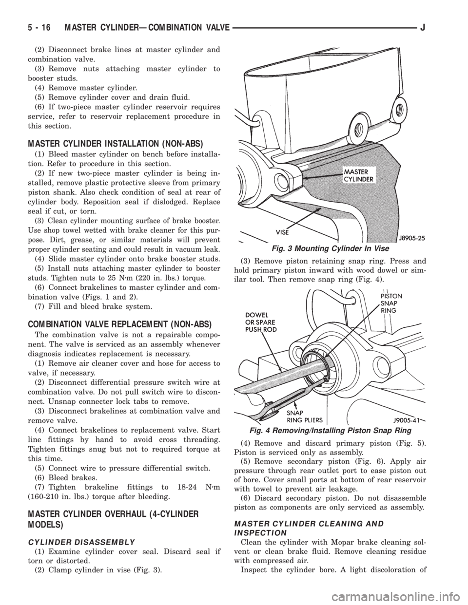
(2) Clamp cylinder in vise (Fig. 3).(3) Remove piston retaining snap ring. Press and
hold primary piston inward with wood dowel or sim-
ilar tool. Then remove snap ring (Fig. 4).
(4) Remove and discard primary piston (Fig. 5).
Piston is serviced only as assembly.
(5) Remove secondary piston (Fig. 6). Apply air
pressure through rear outlet port to ease piston out
of bore. Cover small ports at bottom of rear reservoir
with towel to prevent air leakage.
(6) Discard secondary piston. Do not disassemble
piston as components are only serviced as assembly.
MASTER CYLINDER CLEANING AND
INSPECTION
Clean the cylinder with Mopar brake cleaning sol-
vent or clean brake fluid. Remove cleaning residue
with compressed air.
Inspect the cylinder bore. A light discoloration of
Fig. 3 Mounting Cylinder In Vise
Fig. 4 Removing/Installing Piston Snap Ring
5 - 16 MASTER CYLINDERÐCOMBINATION VALVEJ
Page 173 of 2158
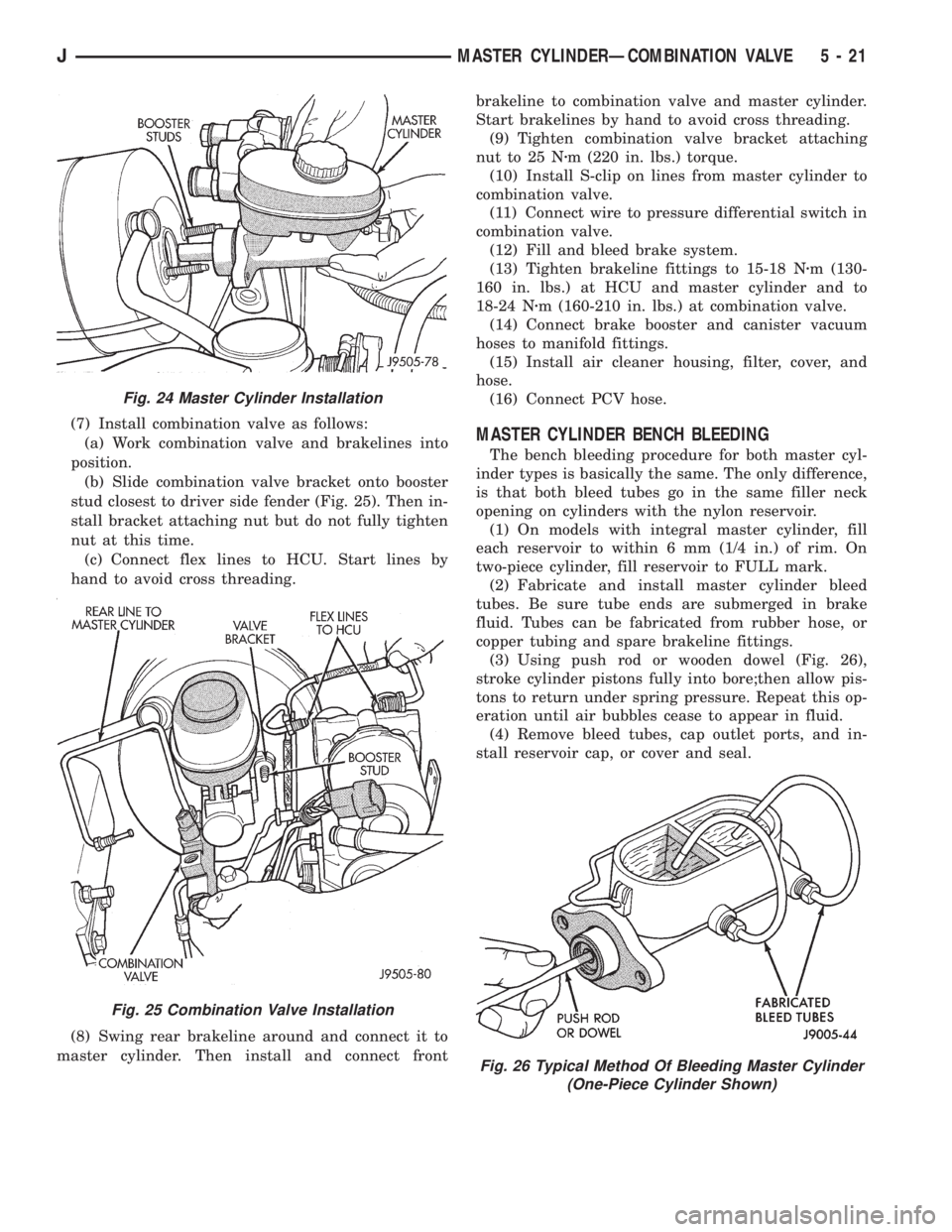
(7) Install combination valve as follows:
(a) Work combination valve and brakelines into
position.
(b) Slide combination valve bracket onto booster
stud closest to driver side fender (Fig. 25). Then in-
stall bracket attaching nut but do not fully tighten
nut at this time.
(c) Connect flex lines to HCU. Start lines by
hand to avoid cross threading.
(8) Swing rear brakeline around and connect it to
master cylinder. Then install and connect frontbrakeline to combination valve and master cylinder.
Start brakelines by hand to avoid cross threading.
(9) Tighten combination valve bracket attaching
nut to 25 Nzm (220 in. lbs.) torque.
(10) Install S-clip on lines from master cylinder to
combination valve.
(11) Connect wire to pressure differential switch in
combination valve.
(12) Fill and bleed brake system.
(13) Tighten brakeline fittings to 15-18 Nzm (130-
160 in. lbs.) at HCU and master cylinder and to
18-24 Nzm (160-210 in. lbs.) at combination valve.
(14) Connect brake booster and canister vacuum
hoses to manifold fittings.
(15) Install air cleaner housing, filter, cover, and
hose.
(16) Connect PCV hose.MASTER CYLINDER BENCH BLEEDING
The bench bleeding procedure for both master cyl-
inder types is basically the same. The only difference,
is that both bleed tubes go in the same filler neck
opening on cylinders with the nylon reservoir.
(1) On models with integral master cylinder, fill
each reservoir to within 6 mm (1/4 in.) of rim. On
two-piece cylinder, fill reservoir to FULL mark.
(2) Fabricate and install master cylinder bleed
tubes. Be sure tube ends are submerged in brake
fluid. Tubes can be fabricated from rubber hose, or
copper tubing and spare brakeline fittings.
(3) Using push rod or wooden dowel (Fig. 26),
stroke cylinder pistons fully into bore;then allow pis-
tons to return under spring pressure. Repeat this op-
eration until air bubbles cease to appear in fluid.
(4) Remove bleed tubes, cap outlet ports, and in-
stall reservoir cap, or cover and seal.
Fig. 24 Master Cylinder Installation
Fig. 25 Combination Valve Installation
Fig. 26 Typical Method Of Bleeding Master Cylinder
(One-Piece Cylinder Shown)
JMASTER CYLINDERÐCOMBINATION VALVE 5 - 21
Page 181 of 2158
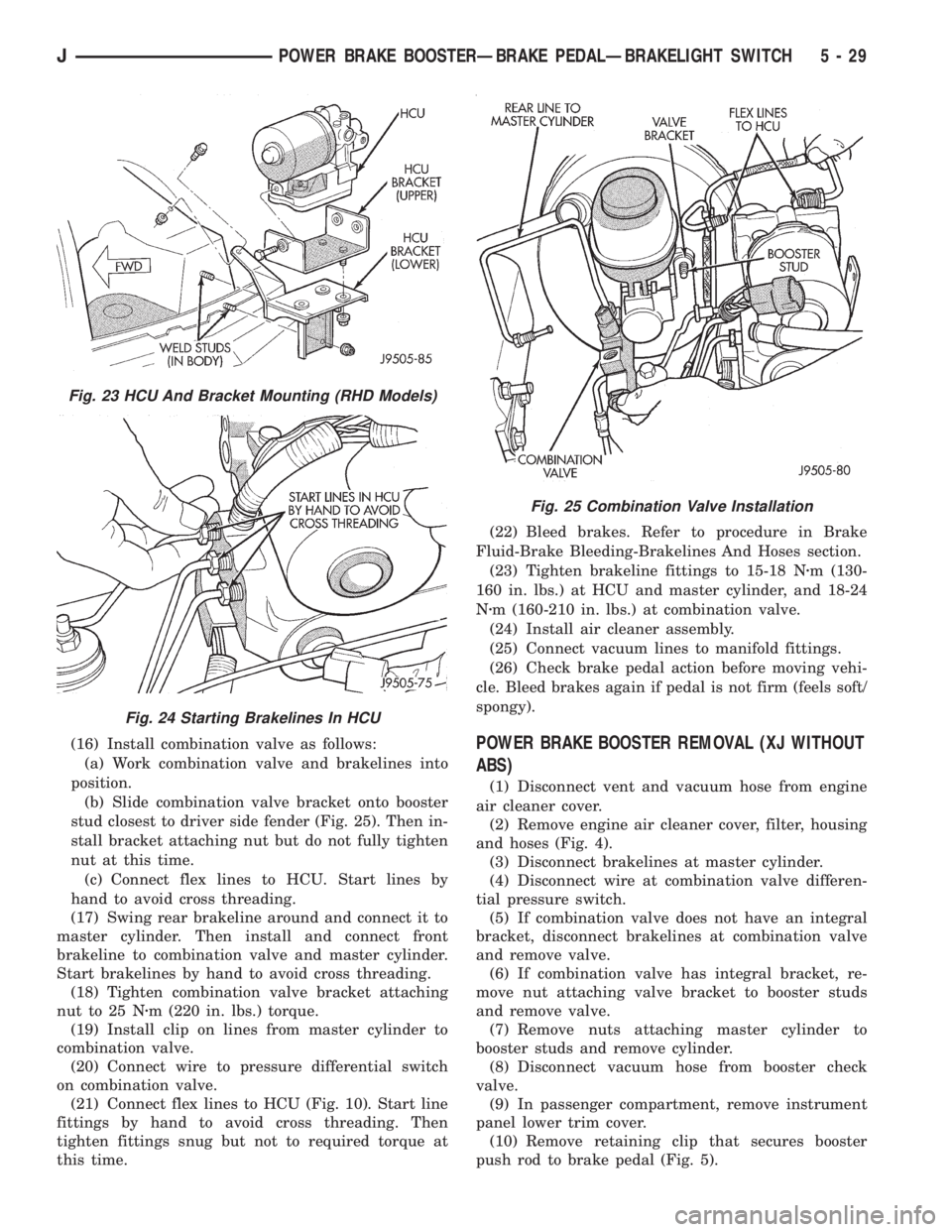
(16) Install combination valve as follows:
(a) Work combination valve and brakelines into
position.
(b) Slide combination valve bracket onto booster
stud closest to driver side fender (Fig. 25). Then in-
stall bracket attaching nut but do not fully tighten
nut at this time.
(c) Connect flex lines to HCU. Start lines by
hand to avoid cross threading.
(17) Swing rear brakeline around and connect it to
master cylinder. Then install and connect front
brakeline to combination valve and master cylinder.
Start brakelines by hand to avoid cross threading.
(18) Tighten combination valve bracket attaching
nut to 25 Nzm (220 in. lbs.) torque.
(19) Install clip on lines from master cylinder to
combination valve.
(20) Connect wire to pressure differential switch
on combination valve.
(21) Connect flex lines to HCU (Fig. 10). Start line
fittings by hand to avoid cross threading. Then
tighten fittings snug but not to required torque at
this time.(22) Bleed brakes. Refer to procedure in Brake
Fluid-Brake Bleeding-Brakelines And Hoses section.
(23) Tighten brakeline fittings to 15-18 Nzm (130-
160 in. lbs.) at HCU and master cylinder, and 18-24
Nzm (160-210 in. lbs.) at combination valve.
(24) Install air cleaner assembly.
(25) Connect vacuum lines to manifold fittings.
(26) Check brake pedal action before moving vehi-
cle. Bleed brakes again if pedal is not firm (feels soft/
spongy).POWER BRAKE BOOSTER REMOVAL (XJ WITHOUT
ABS)
(1) Disconnect vent and vacuum hose from engine
air cleaner cover.
(2) Remove engine air cleaner cover, filter, housing
and hoses (Fig. 4).
(3) Disconnect brakelines at master cylinder.
(4) Disconnect wire at combination valve differen-
tial pressure switch.
(5) If combination valve does not have an integral
bracket, disconnect brakelines at combination valve
and remove valve.
(6) If combination valve has integral bracket, re-
move nut attaching valve bracket to booster studs
and remove valve.
(7) Remove nuts attaching master cylinder to
booster studs and remove cylinder.
(8) Disconnect vacuum hose from booster check
valve.
(9) In passenger compartment, remove instrument
panel lower trim cover.
(10) Remove retaining clip that secures booster
push rod to brake pedal (Fig. 5).
Fig. 23 HCU And Bracket Mounting (RHD Models)
Fig. 24 Starting Brakelines In HCU
Fig. 25 Combination Valve Installation
JPOWER BRAKE BOOSTERÐBRAKE PEDALÐBRAKELIGHT SWITCH 5 - 29
Page 182 of 2158
(11) Remove nuts attaching booster to passenger
compartment side of dash panel.
(12) In engine compartment, slide booster studs
out of dash panel, tilt booster upward, and remove
booster from engine compartment.
(13) Remove dash seal from booster.
(14) If booster is only being removed for access to
other components, cover booster front opening with
clean shop towel.
POWER BRAKE BOOSTER INSTALLATION (XJ
WITHOUT ABS)
(1) If original booster is being installed, test check
valve with vacuum tool before booster installation.
Replace check valve if it will not hold vacuum.
(2) Install dash seal on booster.
(3) Align and position booster on dash panel (Fig.
17).
(4) In passenger compartment, install nuts that at-
tach booster to dash panel. Tighten nuts just enough
to hold booster in place.
(5) Slide booster push rod onto brake pedal. Then
secure push rod to pedal pin with retaining clip.
(6) Tighten booster attaching nuts to 41 Nzm (30 ft.
lbs.) on XJ and 34 Nzm (25 ft. lbs.) on YJ.
(7) Install instrument panel lower trim cover.
(8) If original master cylinder is being installed,
check condition of seal at rear of master cylinder
(Fig. 18). Clean and reposition seal if dislodged. Re-
place seal if cut, or torn.
(9) Clean cylinder mounting surface of brake
booster. Use shop towel wetted with brake cleaner for
this purpose. Dirt, grease, or similar materials will
prevent proper cylinder seating and could result in
vacuum leak.
(10) Align and install master cylinder on booster
studs. Tighten cylinder attaching nuts to 13-25 Nzm
(115-220 in. lbs.) torque.
(11) Connect vacuum hose to booster check valve.
(12) Connect and secure brakelines to combination
valve and master cylinder. Start all brakeline fittings
by hand to avoid cross threading.
(13) If combination valve has integral bracket, po-
sition bracket on booster studs. Then install and
tighten bracket attaching nuts to 13-25 Nzm (115-220
in. lbs.) torque.
(14) Connect wire to combination valve switch.
(15) Top off master cylinder fluid level.
(16) Bleed brakes. Refer to procedures in section
on brake bleeding.
(17) Install engine air cleaner and hoses.
(18) Verify proper brake operation before moving
vehicle.
POWER BRAKE BOOSTER REMOVAL (YJ)
(1) Disconnect brakelines at master cylinder. Then
loosen lines at combination valve and move lines
away from cylinder.
(2) Remove nuts master cylinder to booster studs.
(3) If combination valve has integral bracket, slide
bracket off studs and move valve aside.
(4) Remove master cylinder. Slide cylinder off
studs and remove it from engine compartment.
(5) Working under instrument panel, remove re-
tainer clip that secures booster push rod to brake
pedal.
(6) Disconnect vacuum hose at booster check valve.
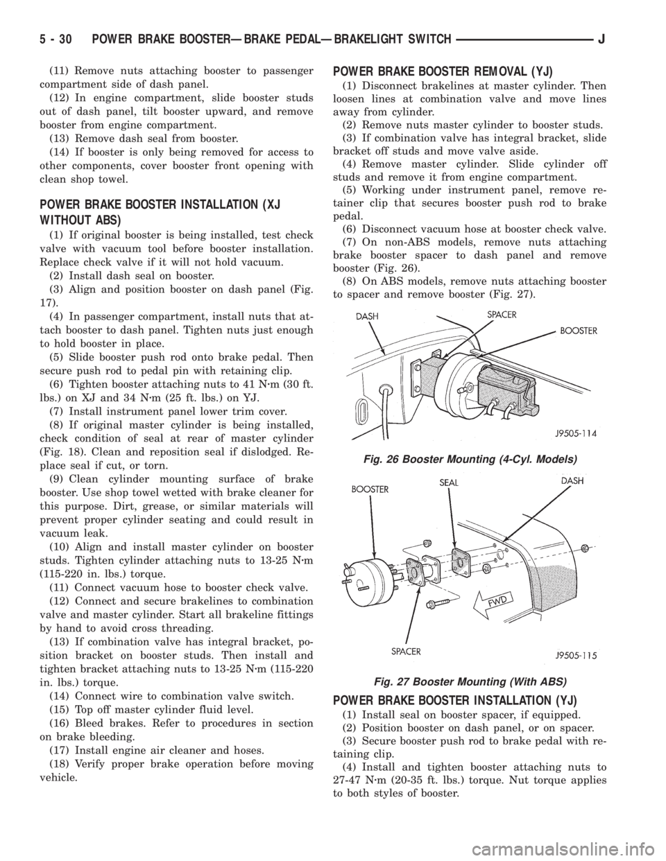
(7) On non-ABS models, remove nuts attaching
brake booster spacer to dash panel and remove
booster (Fig. 26).
(8) On ABS models, remove nuts attaching booster
to spacer and remove booster (Fig. 27).
POWER BRAKE BOOSTER INSTALLATION (YJ)
(1) Install seal on booster spacer, if equipped.
(2) Position booster on dash panel, or on spacer.
(3) Secure booster push rod to brake pedal with re-
taining clip.
(4) Install and tighten booster attaching nuts to
27-47 Nzm (20-35 ft. lbs.) torque. Nut torque applies
to both styles of booster.
Fig. 26 Booster Mounting (4-Cyl. Models)
Fig. 27 Booster Mounting (With ABS)
5 - 30 POWER BRAKE BOOSTERÐBRAKE PEDALÐBRAKELIGHT SWITCHJ
Page 195 of 2158
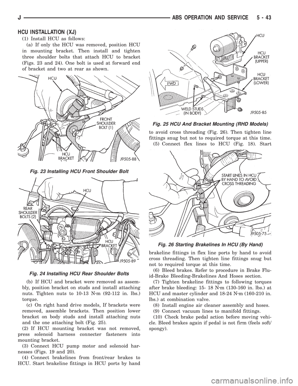
HCU INSTALLATION (XJ)
(1) Install HCU as follows:
(a) If only the HCU was removed, position HCU
in mounting bracket. Then install and tighten
three shoulder bolts that attach HCU to bracket
(Figs. 23 and 24). One bolt is used at forward end
of bracket and two at rear as shown.
(b) If HCU and bracket were removed as assem-
bly, position bracket on studs and install attaching
nuts. Tighten nuts to 10-13 Nzm (92-112 in. lbs.)
torque.
(c) On right hand drive models, If brackets were
removed, assemble brackets. Then position lower
bracket on body studs and install attaching nuts
and the one attaching bolt (Fig. 25).
(2) If HCU mounting bracket was not removed,
press solenoid harness connecter fasteners into
mounting bracket.
(3) Connect HCU pump motor and solenoid har-
nesses (Figs. 19 and 20).
(4) Connect brakelines from front/rear brakes to
HCU. Start brakeline fittings in HCU ports by handto avoid cross threading (Fig. 26). Then tighten line
fittings snug but not to required torque at this time.
(5) Connect flex lines to HCU (Fig. 18). Start
brakeline fittings in flex line ports by hand to avoid
cross threading. Then tighten line fittings snug but
not to required torque at this time.
(6) Bleed brakes. Refer to procedure in Brake Flu-
id-Brake Bleeding-Brakelines And Hoses section.
(7) Tighten brakeline fittings to following torques
after brake bleeding: 15- 18 Nzm (130-160 in. lbs.) at
HCU and master cylinder and 18-24 Nzm (160-210 in.
lbs.) at combination valve.
(8) Install engine air cleaner assembly and hoses.
(9) Connect vacuum lines to manifold fittings.
(10) Check brake pedal action before moving vehi-
cle. Bleed brakes again if pedal is not firm (feels soft/
spongy).
Fig. 23 Installing HCU Front Shoulder Bolt
Fig. 24 Installing HCU Rear Shoulder Bolts
Fig. 25 HCU And Bracket Mounting (RHD Models)
Fig. 26 Starting Brakelines In HCU (By Hand)
JABS OPERATION AND SERVICE 5 - 43
Page 2127 of 2158
BELT TENSIONERÐXJ MODELS WITH
RIGHT HAND DRIVE, AUTOMATIC........7-42
BELT TENSIONÐEXCEPT RIGHT HAND
DRIVE (RHD).........................7-38
BELT TENSIONÐEXCEPT RIGHT HAND
DRIVE (RHD) MODELS.................7-45
BELT TENSIONÐRIGHT HAND DRIVE
(RHD)..............................7-38
BELT/BUCKLEÐXJ, FRONT SHOULDER . . . 23-90
BELT/BUCKLEÐXJ, REAR SHOULDER/
LAP ...............................23-91
BELTLINE SEALÐYJ.................23-142
BELTS, ENGINE ACCESSORY DRIVE.......7-38
BELTSÐYJ, FRONT SHOULDER........23-154
BELTSÐYJ, REAR SHOULDER.........23-154
BENCH BLEEDING, MASTER CYLINDER....5-21
BENCH, GEAR ADJUSTMENTS ON.......19-44
BENCH SEATÐYJ, REAR..............23-153
BEZELÐXJ, INSTRUMENT CLUSTER.....23-80
BEZELÐYJ, INSTRUMENT CLUSTER....23-151
BIN REMOVE/INSTALL, SUNGLASSES
STORAGE...........................8C-7
BLADE REMOVE/INSTALL, WINDSHIELD
WIPER.............................8K-17
BLEEDING, MASTER CYLINDER BENCH....5-21
BLEEDING RECOMMENDATIONS, BRAKE . . . 5-10
BLEEDING (WITH ABS BRAKES), BRAKE . . . 5-11
BLEEDING (WITH STANDARD BRAKES),
BRAKE..............................5-11
BLEEDINGÐBRAKELINES AND HOSES,
BRAKE FLUIDÐBRAKE.................5-10
BLOCK, CYLINDER................9-49,9-91
BLOCK HEATER, ENGINE................7-44
BLOCKSÐTWO-DOOR VEHICLES, FRONT
DOOR SPACER......................23-53
BLOWER MOTOR; AIR CONDITIONING/
HEATER (XJ)......................8W-42-1
BLOWER MOTOR; AIR CONDITIONING/
HEATER (XJ-RHD)..................8W-42-1
BLOWER MOTOR; HEATING AND AIR
CONDITIONING......................24-17
BLOWER MOTOR, A/C.................24-35
BLOWER MOTOR, A/C-HEATER; AIR
CONDITIONING/HEATER (YJ).........8W-42-2
BLOWER MOTOR (HEATING)...........24-33
BLOWER MOTOR RESISTORS
REPLACEMENT......................24-31
BLOWER MOTOR SWITCH.............24-16
BLOWER MOTOR/AIR DOOR MOTOR
SWITCH REPLACEMENT...............24-32
BLOWER MOTOR/FAN REPLACEMENT....24-24
BODY ASSEMBLY AND ADJUSTMENT,
VALVE ............................21-153
BODY CHECK BALL DIMENSIONS, AW-4
VALVE ............................21-341
BODY CODE LETTERS, JEEP..............5-2
BODY LUBRICANT SPECIFICATIONS.......0-33
BODY OVERHAUL, TRANSMISSION
VALVE ............................21-250
BODY REMOVAL, TRANSMISSION VALVE . 21-186
BODY REMOVAL, VALVE..............21-104
BODY SERVICE INFORMATION, GENERAL . . 23-1
BODY SERVICE, VALVE...............21-104
BODY SIDE MOLDING/CLADDINGÐXJ....23-20
BODY SIDE STEP MOLDINGÐYJ.......23-115
BODY SOLENOIDS, TRANSMISSION
VALVE ............................21-184
BODY STRIPES/DECALSÐXJ...........23-21
BODY STRIPES/DECALSÐYJ..........23-116
BODY, THROTTLE...............14-33,14-64
BOLT IDENTIFICATION..............Intro.-14
BOLT STRENGTH..................Intro.-15
BOOSTER CHECK VALVE TEST, POWER.....5-9
BOOSTER INSTALLATION (XJ WITH
ABS), POWER BRAKE..................5-27
BOOSTER INSTALLATION (XJ WITHOUT
ABS), POWER BRAKE..................5-30
BOOSTER INSTALLATION (YJ), POWER
BRAKE..............................5-30
BOOSTER, MASTER CYLINDER/POWER
BRAKE
..............................5-34
BOOSTER OPERATION, POWER BRAKE
....5-23
BOOSTER REMOVAL (XJ WITH ABS),
POWER BRAKE
.......................5-24
BOOSTER REMOVAL (XJ WITHOUT ABS),
POWER BRAKE
.......................5-29
BOOSTER REMOVAL (YJ), POWER
BRAKE
..............................5-30BOOSTER TEST, MASTER CYLINDER/
POWER..............................5-8
BOOSTER VACUUM TEST, POWER.........5-9
BOOSTERÐBRAKE PEDALÐ
BRAKELIGHT SWITCH, POWER BRAKE....5-22
BORES, HONING CYLINDER..............9-2
BOX LAMP, GLOVE; INTERIOR LIGHTING
(XJ).............................8W-44-1
BOX LAMP, GLOVE; INTERIOR LIGHTING
(XJ-RHD).........................8W-44-1
BOXÐYJ, GLOVE...................23-152
BRACKET REPLACEMENTÐXJ, INTERIOR
REARVIEW MIRROR SUPPORT..........23-68
BRACKETÐYJ, REARVIEW MIRROR
RETAINING........................23-144
BRACKETSÐXJ, SPARE TIRE/WHEEL
HOLDDOWN AND FLOOR..............23-98
BRAKE ADJUSTMENT, DRUM............5-57
BRAKE BLEEDING RECOMMENDATIONS....5-10
BRAKE BLEEDING (WITH ABS BRAKES)....5-11
BRAKE BLEEDING (WITH STANDARD
BRAKES)............................5-11
BRAKE BOOSTER INSTALLATION (XJ
WITH ABS), POWER...................5-27
BRAKE BOOSTER INSTALLATION (XJ
WITHOUT ABS), POWER................5-30
BRAKE BOOSTER INSTALLATION (YJ),
POWER.............................5-30
BRAKE BOOSTER, MASTER CYLINDER/
POWER.............................5-34
BRAKE BOOSTER OPERATION, POWER....5-23
BRAKE BOOSTER REMOVAL (XJ WITH
ABS), POWER........................5-24
BRAKE BOOSTER REMOVAL (XJ
WITHOUT ABS), POWER................5-29
BRAKE BOOSTER REMOVAL (YJ),
POWER.............................5-30
BRAKE BOOSTERÐBRAKE PEDALÐ
BRAKELIGHT SWITCH, POWER...........5-22
BRAKE CABLE TENSIONER ADJUSTMENT
(XJ/YJ), PARKING.....................5-69
BRAKE CABLE TENSIONER
REPLACEMENT (XJ), PARKING...........5-66
BRAKE CHECK, PRELIMINARY............5-4
BRAKE COMPONENTS...................5-1
BRAKE DIAGNOSIS, ABS.................5-3
BRAKE DIAGNOSIS, SERVICE.............5-4
BRAKE DRUM REFINISHING.............5-58
BRAKE FLUID CONTAMINATION.......5-10,5-7
BRAKE FLUID LEVEL...................5-10
BRAKE FLUID, RECOMMENDED..........5-10
BRAKE FLUID/LUBRICANTS/CLEANING
SOLVENTS............................5-2
BRAKE FLUIDÐBRAKE BLEEDINGÐ
BRAKELINES AND HOSES...............5-10
BRAKE FRONT CABLE REPLACEMENT
(YJ), PARKING........................5-67
BRAKE HANDLE COVERÐXJ, PARKING . . . 23-94
BRAKE LEVER INSTALLATION (XJ WITH
FULL CONSOLE), PARKING..............5-64
BRAKE LEVER INSTALLATION (XJ WITH
MINI CONSOLE), PARKING..............5-63
BRAKE LEVER INSTALLATION (XJ
WITHOUT CONSOLE), PARKING..........5-65
BRAKE LEVER REMOVAL (XJ WITH FULL
CONSOLE), PARKING..................5-63
BRAKE LEVER REMOVAL (XJ WITH MINI
CONSOLE), PARKING..................5-62
BRAKE LEVER REMOVAL (XJ WITHOUT
CONSOLE), PARKING
..................5-64
BRAKE MALFUNCTIONS, DIAGNOSING
PARKING
.............................5-8
BRAKE NOISE
.........................5-7
BRAKE OPERATION, PARKING
...........5-60
BRAKE OVERHAUL, SECOND
..........21-241
BRAKE PACK REQUIREMENTS, AW-4
CLUTCH
...........................21-341
BRAKE PEDAL BUSHINGS, CLUTCH
.......0-22
BRAKE PEDAL INSTALLATION
............5-31
BRAKE PEDAL INSTALLATION (YJ),
PARKING
............................5-66
BRAKE PEDAL REMOVAL
...............5-31
BRAKE PEDAL REMOVAL (YJ), PARKING
. . . 5-66
BRAKE PEDAL TRAVEL SENSOR;
ANTI-LOCK BRAKES (YJ)
............8W-32-1
BRAKE PISTON AND TRANSMISSION
CASE OVERHAUL, FIRST-REVERSE
......21-247BRAKE REAR CABLE REPLACEMENT
(XJ), PARKING........................5-67
BRAKE REAR CABLE REPLACEMENT
(YJ), PARKING........................5-68
BRAKE ROTOR REFINISHING, DISC.......5-53
BRAKE ROTOR RUNOUT, DISC...........5-52
BRAKE ROTOR THICKNESS, DISC........5-52
BRAKE SAFETY PRECAUTIONS............5-2
BRAKE SWITCH......................14-59
BRAKE SWITCH INPUT; ANTI-LOCK
BRAKES (XJ)......................8W-32-2
BRAKE SWITCH INPUT; ANTI-LOCK
BRAKES (XJ-RHD).................8W-32-2
BRAKE SWITCH INPUT; ANTI-LOCK
BRAKES (YJ)......................8W-32-2
BRAKE SWITCH INPUT; FUEL/IGNITION
(XJ).............................8W-30-5
BRAKE SWITCH INPUT; FUEL/IGNITION
(YJ).............................8W-30-5
BRAKE SWITCH INPUT; FUEL/IGNITION
(XJ-RHD).........................8W-30-5
BRAKE SWITCH, PARKING..............5-68
BRAKE SWITCHÐPCM INPUT..........14-22
BRAKE SYSTEM, POWER...............0-30
BRAKE TORQUE SPECIFICATIONS.........5-70
BRAKE WARNING LAMP; INSTRUMENT
CLUSTER (XJ).....................8W-40-2
BRAKE WARNING LAMP; INSTRUMENT
CLUSTER (XJ-RHD)................8W-40-2
BRAKE WARNING LAMP; INSTRUMENT
CLUSTER (YJ)......................8W-40-2
BRAKE WARNING LIGHTS................5-1
BRAKELIGHT SWITCH ADJUSTMENT......5-32
BRAKELIGHT SWITCH INSTALLATION......5-32
BRAKELIGHT SWITCH REMOVAL.........5-32
BRAKELINE CHARTS...................5-12
BRAKELINES AND HOSES...............5-12
BRAKELINING, CONTAMINATED...........5-7
BRAKELINING MATERIAL................5-1
BRAKES (ABS), ANTILOCK...............5-1
BRAKES, DISC........................5-45
BRAKES DO NOT HOLD AFTER DRIVING
THROUGH DEEP WATER PUDDLES........5-7
BRAKES, DRUM......................5-55
BRAKES, PARKING....................5-60
BRAKESHOE INSTALLATION, DISC........5-47
BRAKESHOE INSTALLATION, DRUM.......5-55
BRAKESHOE REMOVAL, DISC............5-46
BRAKESHOE REMOVAL, DRUM...........5-55
BRAKING MODE, ABS OPERATION IN
ANTILOCK...........................5-36
BRAKING MODE, ABS OPERATION IN
NORMAL............................5-35
BREAK-IN, ENGINE....................0-15
BRUSH GUARDÐXJ...................23-3
BUCKET SEAT CUSHION AND COVERÐ
XJ ................................23-81
BUCKET SEAT PLATFORMÐXJ..........23-82
BUCKET SEATBACK COVER AND
FRAMEÐXJ.........................23-81
BUCKET SEATSÐXJ, FRONT............23-81
BUCKET SEATSÐYJ.................23-153
BULB APPLICATIONÐXJ VEHICLES......8L-18
BULB APPLICATIONÐYJ VEHICLES......8L-32
BULB REMOVE/INSTALL, READING/
COURTESY LAMP.....................8C-8
BULB REPLACEMENTÐXJ, BACK-UP/
REAR TURN SIGNAL/TAIL LAMP.........8L-12
BULB REPLACEMENTÐXJ, FRONT
PARK/TURN SIGNAL LAMP..............8L-9
BULB REPLACEMENTÐXJ, HEADLAMP....8L-7
BULB REPLACEMENTÐXJ, SIDE
MARKER LAMP......................8L-10
BULB REPLACEMENTÐXJ, UNDERHOOD
LAMP..............................8L-13
BULB REPLACEMENTÐYJ, BACK-UP/
REAR TURN SIGNAL/TAIL LAMP.........8L-28
BULB REPLACEMENTÐYJ, FRONT
PARK/TURN SIGNAL LAMP.............8L-25
BULB REPLACEMENTÐYJ, HEADLAMP . . . 8L-23
BULB REPLACEMENTÐYJ, SIDE
MARKER LAMP
......................8L-25
BULB REPLACEMENTÐYJ, UNDERHOOD
LAMP
..............................8L-29
BULB REPLACEMENTÐYJ VEHICLES,
HARDTOP DOME/CARGO LAMP
.........8L-31
BUMPER, FRONT
.................13-16,13-5
BUMPER, REAR
..................13-16,13-8
JINDEX 3
Description Group-Page Description Group-Page Description Group-Page