ignition KIA Borrego 2010 1.G Owners Manual
[x] Cancel search | Manufacturer: KIA, Model Year: 2010, Model line: Borrego, Model: KIA Borrego 2010 1.GPages: 461, PDF Size: 12.25 MB
Page 370 of 461
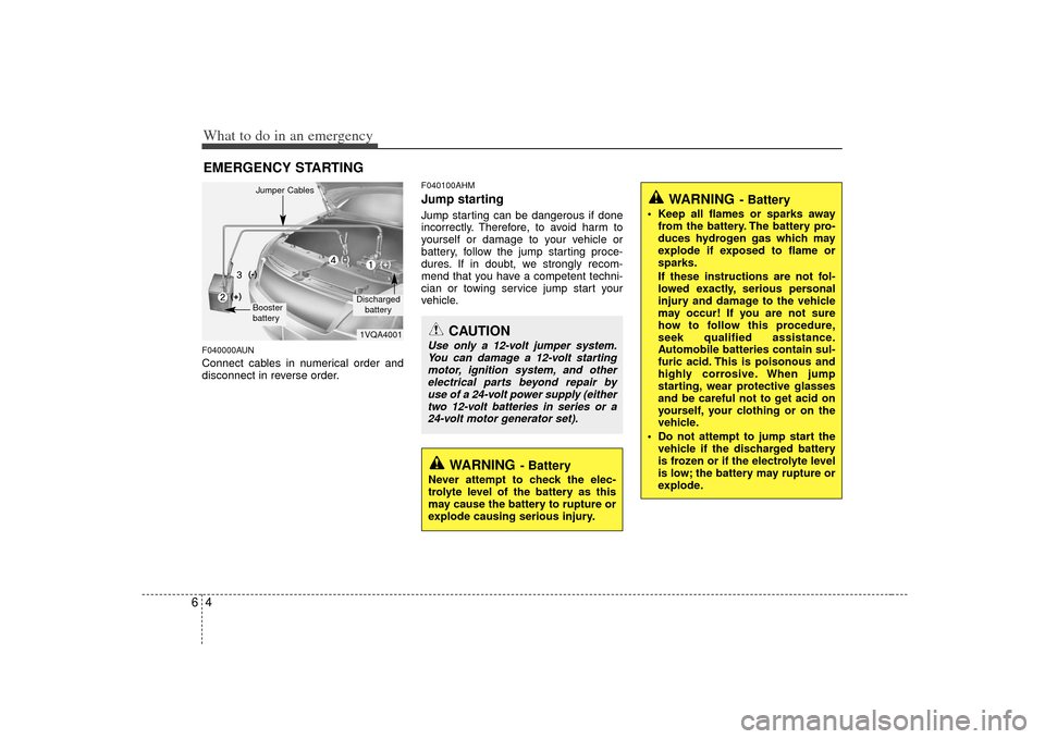
What to do in an emergency46EMERGENCY STARTINGF040000AUNConnect cables in numerical order and
disconnect in reverse order.
F040100AHMJump starting Jump starting can be dangerous if done
incorrectly. Therefore, to avoid harm to
yourself or damage to your vehicle or
battery, follow the jump starting proce-
dures. If in doubt, we strongly recom-
mend that you have a competent techni-
cian or towing service jump start your
vehicle.
CAUTION
Use only a 12-volt jumper system.You can damage a 12-volt startingmotor, ignition system, and other electrical parts beyond repair byuse of a 24-volt power supply (either two 12-volt batteries in series or a24-volt motor generator set).
WARNING
- Battery
• Keep all flames or sparks away from the battery. The battery pro-
duces hydrogen gas which may
explode if exposed to flame or
sparks.
If these instructions are not fol-
lowed exactly, serious personal
injury and damage to the vehicle
may occur! If you are not sure
how to follow this procedure,
seek qualified assistance.
Automobile batteries contain sul-
furic acid. This is poisonous and
highly corrosive. When jump
starting, wear protective glasses
and be careful not to get acid on
yourself, your clothing or on the
vehicle.
Do not attempt to jump start the vehicle if the discharged battery
is frozen or if the electrolyte level
is low; the battery may rupture or
explode.
WARNING
- Battery
Never attempt to check the elec-
trolyte level of the battery as this
may cause the battery to rupture or
explode causing serious injury.
1VQA4001Discharged
battery
Jumper CablesBooster
battery(-)
(+)
(+)
(-)
Page 387 of 461
621
What to do in an emergency
When towing your vehicle in an emer-
gency without wheel dollies :
1. Set the ignition switch in the ACC posi-tion.
2. Place the transmission shift lever in N (Neutral).
3. For part-time 4WD vehicle, set the transfer shift knob to 2H.
4. Release the parking brake.
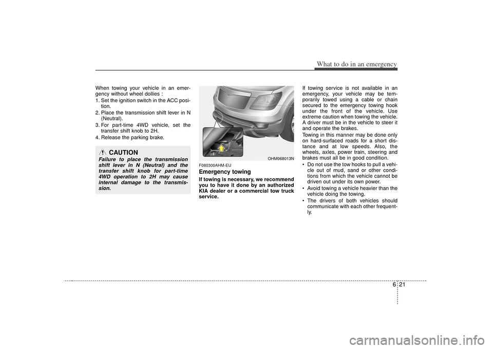
F080300AHM-EUEmergency towingIf towing is necessary, we recommend
you to have it done by an authorized
KIA dealer or a commercial tow truck
service. If towing service is not available in an
emergency, your vehicle may be tem-
porarily towed using a cable or chain
secured to the emergency towing hook
under the front of the vehicle. Use
extreme caution when towing the vehicle.
A driver must be in the vehicle to steer it
and operate the brakes.
Towing in this manner may be done only
on hard-surfaced roads for a short dis-
tance and at low speeds. Also, the
wheels, axles, power train, steering and
brakes must all be in good condition.
Do not use the tow hooks to pull a vehi-
cle out of mud, sand or other condi-
tions from which the vehicle cannot be
driven out under its own power.
Avoid towing a vehicle heavier than the vehicle doing the towing.
The drivers of both vehicles should communicate with each other frequent-
ly.
OHM068013N
CAUTION
Failure to place the transmissionshift lever in N (Neutral) and thetransfer shift knob for part-time 4WD operation to 2H may causeinternal damage to the transmis-sion.
Page 389 of 461
623
What to do in an emergency
F080301AHM-EUEmergency towing precautions Turn the ignition switch to ACC so thesteering wheel isn’t locked.
Place the transmission shift lever in N (Neutral).
Release the parking bake.
Press the brake pedal with more force than usual since you will have reduced
brake performance.
More steering effort will be required because the power steering system
will be disabled.
If you are driving down a long hill, the brakes may overheat and brake per-
formance will be reduced. Stop often
and let the brakes cool off.
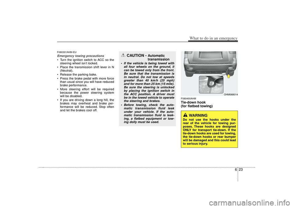
F080400AHMTie-down hook
(for flatbed towing)
OHM068014
CAUTION -
Automatic
transmission
If the vehicle is being towed with
all four wheels on the ground, itcan be towed only from the front. Be sure that the transmission isin neutral. Do not tow at speeds greater than 40 km/h (25 mph)and for more than 25 km (15 mile). Be sure the steering is unlockedby placing the ignition switch in the ACC position. A driver mustbe in the towed vehicle to operate the steering and brakes.
Before towing, check the auto- matic transmission fluid leakunder your vehicle. If the auto- matic transmission fluid is leak-ing, a flatbed equipment or tow- ing dolly must be used.
WARNING
Do not use the hooks under the
rear of the vehicle for towing pur-
poses. These hooks are designed
ONLY for transport tie-down. If the
tie-down hooks are used for towing,
the tie-down hooks or rear bumper
will be damaged and this could lead
to serious injury.
Page 396 of 461
77
Maintenance
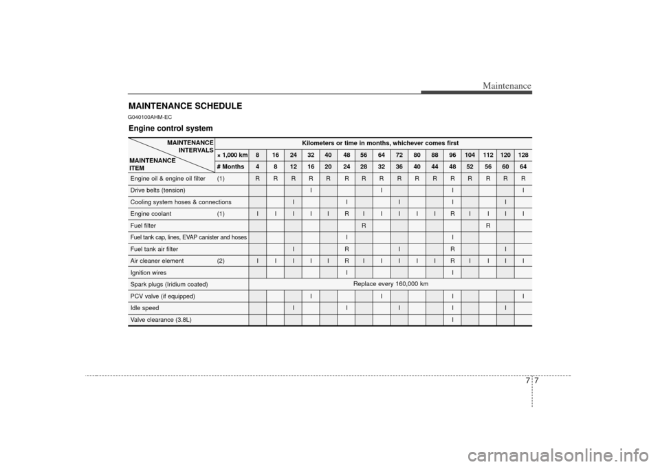
MAINTENANCE SCHEDULEG040100AHM-EC
MAINTENANCEINTERVALS
MAINTENANCE
ITEM
Engine control system
Kilometers or time in months, whichever comes first
× 1,000 km 8 16 24 32 40 48 56 64 72 80 88 96 104 112 120 128
# Months 4 8 12 16 20 24 28 32 36 40 44 48 52 56 60 64
Engine oil & engine oil filter (1) R R R R R R RRRRRRR RRR
Drive belts (tension) I I I I
Cooling system hoses & connections I I I I I
Engine coolant (1) I I I I I R IIIIIRI III
Fuel filter RR
Fuel tank cap, lines, EVAP canister and hoses
II
Fuel tank air filter I R I R I
Air cleaner element (2) I I I I I R IIIIIRI III
Ignition wires I I
Spark plugs (Iridium coated)
PCV valve (if equipped) I I I I
Idle speed I I I I I
Valve clearance (3.8L) IReplace every 160,000 km
Page 415 of 461
Maintenance26
7
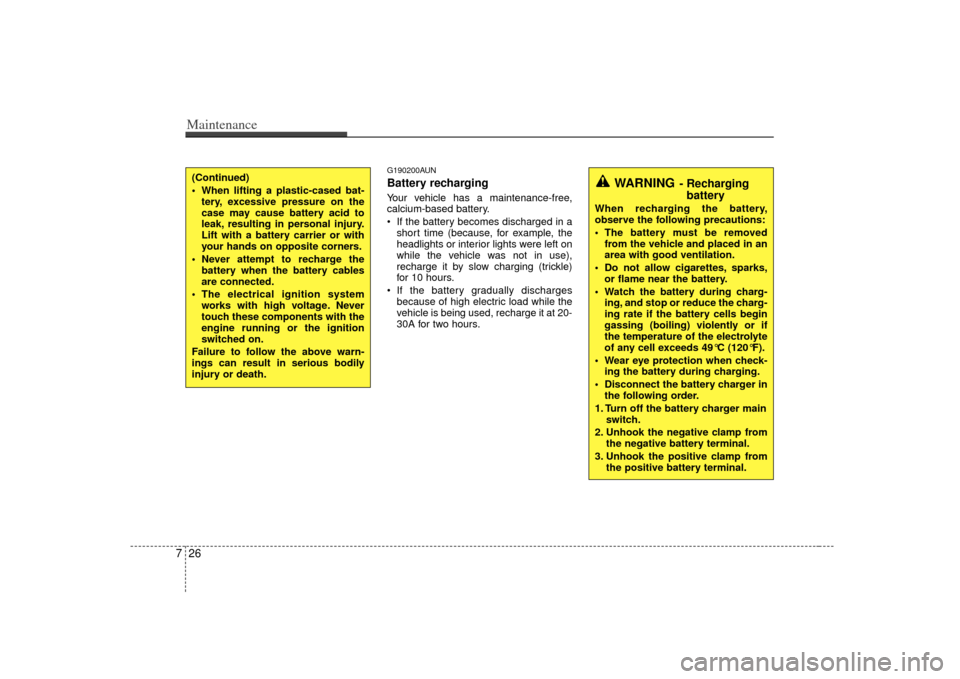
G190200AUNBattery recharging Your vehicle has a maintenance-free,
calcium-based battery.
If the battery becomes discharged in a
short time (because, for example, the
headlights or interior lights were left on
while the vehicle was not in use),
recharge it by slow charging (trickle)
for 10 hours.
If the battery gradually discharges because of high electric load while the
vehicle is being used, recharge it at 20-
30A for two hours.
(Continued)
When lifting a plastic-cased bat-tery, excessive pressure on the
case may cause battery acid to
leak, resulting in personal injury.
Lift with a battery carrier or with
your hands on opposite corners.
Never attempt to recharge the battery when the battery cables
are connected.
The electrical ignition system works with high voltage. Never
touch these components with the
engine running or the ignition
switched on.
Failure to follow the above warn-
ings can result in serious bodily
injury or death.
WARNING
- Recharging battery
When recharging the battery,
observe the following precautions:
The battery must be removed
from the vehicle and placed in an
area with good ventilation.
Do not allow cigarettes, sparks, or flame near the battery.
Watch the battery during charg- ing, and stop or reduce the charg-
ing rate if the battery cells begin
gassing (boiling) violently or if
the temperature of the electrolyte
of any cell exceeds 49°C (120°F).
Wear eye protection when check- ing the battery during charging.
Disconnect the battery charger in the following order.
1. Turn off the battery charger main switch.
2. Unhook the negative clamp from the negative battery terminal.
3. Unhook the positive clamp from the positive battery terminal.
Page 432 of 461
743
Maintenance
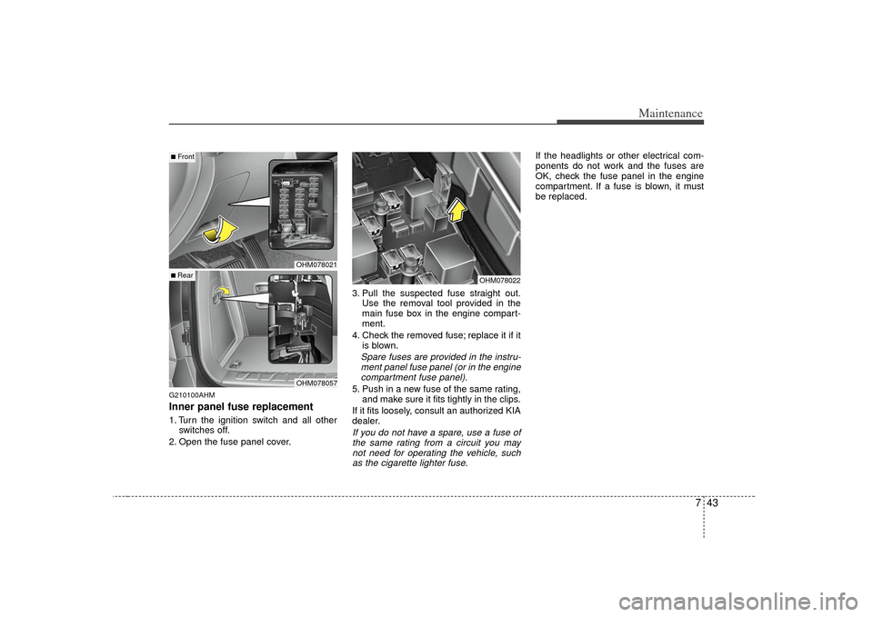
G210100AHMInner panel fuse replacement1. Turn the ignition switch and all otherswitches off.
2. Open the fuse panel cover. 3. Pull the suspected fuse straight out.
Use the removal tool provided in the
main fuse box in the engine compart-
ment.
4. Check the removed fuse; replace it if it is blown.
Spare fuses are provided in the instru-ment panel fuse panel (or in the enginecompartment fuse panel).5. Push in a new fuse of the same rating, and make sure it fits tightly in the clips.
If it fits loosely, consult an authorized KIA
dealer.If you do not have a spare, use a fuse of the same rating from a circuit you maynot need for operating the vehicle, such as the cigarette lighter fuse.
If the headlights or other electrical com-
ponents do not work and the fuses are
OK, check the fuse panel in the engine
compartment. If a fuse is blown, it must
be replaced.
OHM078022
OHM078021OHM078057
■Front■ Rear
Page 433 of 461
Maintenance44
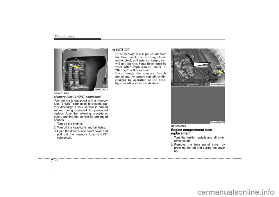
7G210101AHMMemory fuse (SHUNT connector)Your vehicle is equipped with a memory
fuse (SHUNT connector) to prevent bat-
tery discharge if your vehicle is parked
without being operated for prolonged
periods. Use the following procedures
before parking the vehicle for prolonged
periods.
1. Turn off the engine.
2. Turn off the headlights and tail lights.
3. Open the driver’s side panel cover and
pull out the memory fuse (SHUNT
connector).
✽ ✽NOTICE• If the memory fuse is pulled out from
the fuse panel, the warning chime,
audio, clock and interior lamps, etc.,
will not operate. Some items must be
reset after replacement. Refer to
“Battery” in this section.
• Even though the memory fuse is pulled out, the battery can still be dis-
charged by operation of the head-
lights or other electrical devices.
G210200AHMEngine compartment fuse
replacement1. Turn the ignition switch and all other
switches off.
2. Remove the fuse panel cover by pressing the tab and pulling the cover
up.
OHM078023
OHM078024NOHM078025N
Page 436 of 461
747
Maintenance
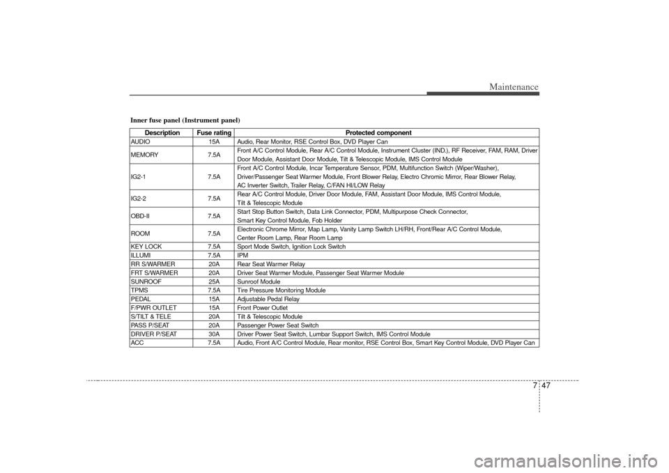
Inner fuse panel (Instrument panel)
Description Fuse ratingProtected component
AUDIO15A Audio, Rear Monitor, RSE Control Box, DVD Player Can
MEMORY 7.5AFront A/C Control Module, Rear A/C Control Module, Instrument Cluster (IND.), RF Receiver, FAM, RAM, Driver
Door Module, Assistant Door Module, Tilt & Telescopic Module, IMS Control Module
Front A/C Control Module, Incar Temperature Sensor, PDM, Multifunction Switch (Wiper/Washer),
IG2-1 7.5A Driver/Passenger Seat Warmer Module, Front Blower Relay, Electro Chromic Mirror, Rear Blower Relay,
AC Inverter Switch, Trailer Relay, C/FAN HI/LOW Relay
IG2-2 7.5ARear A/C Control Module, Driver Door Module, FAM, Assistant Door Module, IMS Control Module,
Tilt & Telescopic Module
OBD-II 7.5AStart Stop Button Switch, Data Link Connector, PDM, Multipurpose Check Connector,
Smart Key Control Module, Fob Holder
ROOM 7.5AElectronic Chrome Mirror, Map Lamp, Vanity Lamp Switch LH/RH, Front/Rear A/C Control Module,
Center Room Lamp, Rear Room Lamp
KEY LOCK 7.5A Sport Mode Switch, Ignition Lock Switch
ILLUMI 7.5A IPM
RR S/WARMER 20A Rear Seat Warmer Relay
FRT S/WARMER 20A Driver Seat Warmer Module, Passenger Seat Warmer Module
SUNROOF 25A Sunroof Module
TPMS 7.5A Tire Pressure Monitoring Module
PEDAL 15A Adjustable Pedal Relay
F/PWR OUTLET 15A Front Power Outlet
S/TILT & TELE 20A Tilt & Telescopic Module
PASS P/SEAT 20A Passenger Power Seat Switch
DRIVER P/SEAT 30A Driver Power Seat Switch, Lumbar Support Switch, IMS Control Module
ACC 7.5A Audio, Front A/C Control Module, Rear monitor, RSE Control Box, Smart Key Control Module, DVD Player Can
Page 439 of 461
Maintenance50
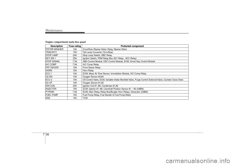
7Engine compartment main fuse panel
Description Fuse rating Protected component
FRT/RR WASHER 10A Front/Rear Washer Motor Relay, Washer Motor
TRAILER 5 15A Tail Lamp Converter (Turn/Stop)
STOP LAMP 20A Stop Lamp Switch, DBC Relay
KEY SW 1 25A Ignition Switch, PDM Relay Box (IG1 Relay , ACC Relay)
STOP SIGNAL 7.5A ABS Control Module, ESC Control Module, ECM, Smart Key Control Module
A/C COMP 7.5A A/C Comp Relay
FRT DEICER 15A Front Deicer Relay
HORN 15A Horn Relay
ECU 1 10A ECM, Mass Air Flow Sensor, Immobilizer Module, A/C Comp Relay
O2 DN 10A Oxygen Sensor #3,#4
ECU 2 15A Oil Control Valve, ECM, Variable Intake Manifold Valve, Purge Control Solenoid Valve, Canister Close Valve
O2 UP 10A Oxygen Sensor #1,#2
IGN COIL 20A Ignition Coil #1~#8, Condenser #1,#2
INJECTOR 15A ECM, Injector #1~#8, Camshaft Position Sensor #1 ~ #3 (G8BA)
P/TRAIN 7.5A ECM, Main Relay, Relay Box(Burglar Horn Relay), Generator (G8BA)
FUEL PUMP 15A Fuel Pump Relay, Fuel Sender & Fuel Pump Motor
ATM 15A TCM
Page 440 of 461
751
Maintenance
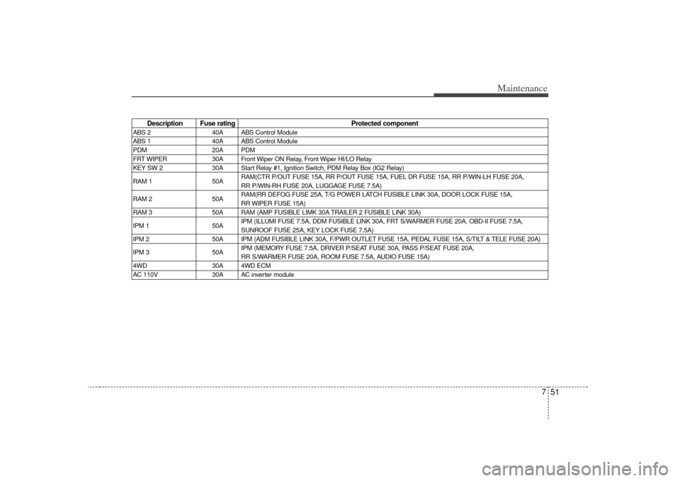
Description Fuse ratingProtected component
ABS 240A ABS Control Module
ABS 1 40A ABS Control Module
PDM 20A PDM
FRT WIPER 30A Front Wiper ON Relay, Front Wiper HI/LO Relay
KEY SW 2 30A Start Relay #1, Ignition Switch, PDM Relay Box (IG2 Relay)
RAM 1 50ARAM(CTR P/OUT FUSE 15A, RR P/OUT FUSE 15A, FUEL DR FUSE 15A, RR P/WIN-L\
H FUSE 20A,
RR P/WIN-RH FUSE 20A, LUGGAGE FUSE 7.5A)
RAM 2 50ARAM(RR DEFOG FUSE 25A, T/G POWER LATCH FUSIBLE LINK 30A, DOOR LOCK FUSE 15A,
RR WIPER FUSE 15A)
RAM 3 50A RAM (AMP FUSIBLE LIMK 30A TRAILER 2 FUSIBLE LINK 30A)
IPM 1 50AIPM (ILLUMI FUSE 7.5A, DDM FUSIBLE LINK 30A, FRT S/WARMER FUSE 20A, OBD-II FUSE 7.5A,
SUNROOF FUSE 25A, KEY LOCK FUSE 7.5A)
IPM 2 50A IPM (ADM FUSIBLE LINK 30A, F/PWR OUTLET FUSE 15A, PEDAL FUSE 15A, S/TILT & TELE FUSE 20A)
IPM 3 50AIPM (MEMORY FUSE 7.5A, DRIVER P/SEAT FUSE 30A, PASS P/SEAT FUSE 20A,
RR S/WARMER FUSE 20A, ROOM FUSE 7.5A, AUDIO FUSE 15A)
4WD 30A 4WD ECM
AC 110V 30A AC inverter module