KIA CARNIVAL 2007 Workshop Manual
CARNIVAL 2007
KIA
KIA
https://www.carmanualsonline.info/img/2/57045/w960_57045-0.png
KIA CARNIVAL 2007 Workshop Manual
Page 646 of 1575

2007 > 2.7L V6 GASOLINE >
TROUBLESHOOTING
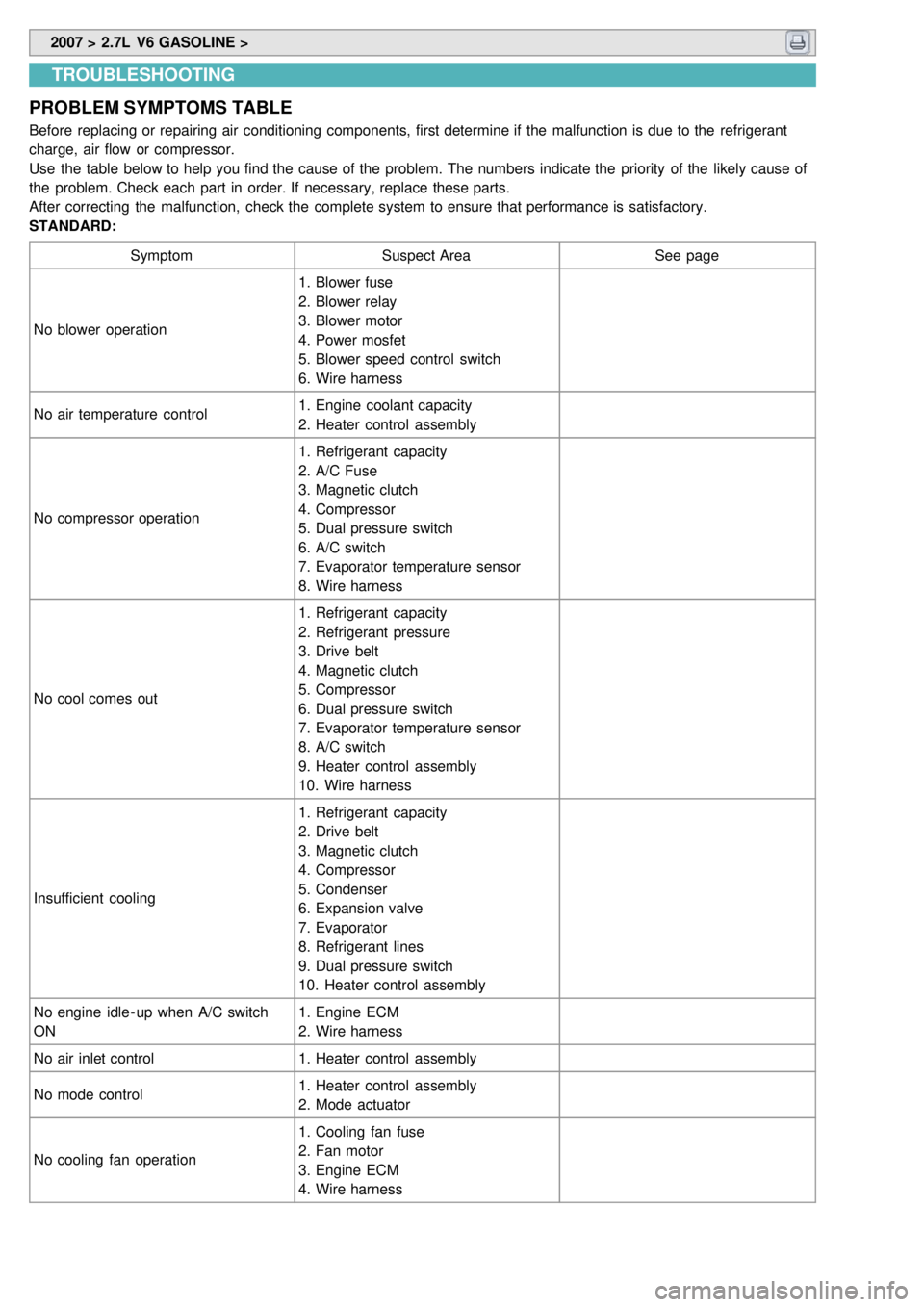
PROBLEM SYMPTOMS TABLE
Before replacing or repairing air conditioning components, first determine if the malfunction is due to the refrigerant
charge, air flow or compressor.
Use the table below to help you find the cause of the problem. The numbers indicate the priority of the likely cause of
the problem. Check each part in order. If necessary, replace these parts.
After correcting the malfunction, check the complete system to ensure that performance is satisfactory.
STANDARD:
Symptom Suspect Area See page
No blower operation 1. Blower fuse
2. Blower relay
3. Blower motor
4. Power mosfet
5. Blower speed control switch
6. Wire harness
No air temperature control 1. Engine coolant capacity
2. Heater control assembly
No compressor operation 1. Refrigerant capacity
2. A/C Fuse
3. Magnetic clutch
4. Compressor
5. Dual pressure switch
6. A/C switch
7. Evaporator temperature sensor
8. Wire harness
No cool comes out 1. Refrigerant capacity
2. Refrigerant pressure
3. Drive belt
4. Magnetic clutch
5. Compressor
6. Dual pressure switch
7. Evaporator temperature sensor
8. A/C switch
9. Heater control assembly
10. Wire harness
Insufficient cooling 1. Refrigerant capacity
2. Drive belt
3. Magnetic clutch
4. Compressor
5. Condenser
6. Expansion valve
7. Evaporator
8. Refrigerant lines
9. Dual pressure switch
10. Heater control assembly
No engine idle - up when A/C switch
ON 1. Engine ECM
2. Wire harness
No air inlet control 1. Heater control assembly
No mode control 1. Heater control assembly
2. Mode actuator
No cooling fan operation 1. Cooling fan fuse
2. Fan motor
3. Engine ECM
4. Wire harness
Page 647 of 1575

2007 > 2.7L V6 GASOLINE >
SPECIFICATION
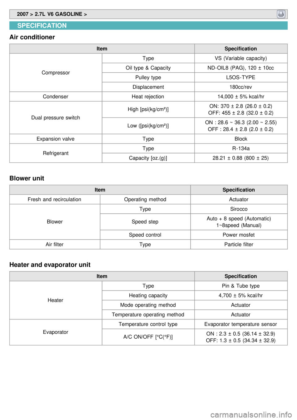
Air conditioner
Item Specification
Compressor Type
VS (Variable capacity)
Oil type & Capacity ND- OIL8 (PAG), 120 ± 10cc
Pulley type L5OS - TYPE
Displacement 180cc/rev
Condenser Heat rejection14,000 ± 5% kcal/hr
Dual pressure switch High [psi(kg/cm²)]
ON: 370 ± 2.8 (26.0 ± 0.2)
OFF: 455 ± 2.8 (32.0 ± 0.2)
Low ([psi(kg/cm²)] ON : 28.6 ~ 36.3 (2.00 ~ 2.55)
OFF : 28.4 ± 2.8 (2.0 ± 0.2)
Expansion valve TypeBlock
Refrigerant Type
R- 134a
Capacity [oz.(g)] 28.21 ± 0.88 (800 ± 25)
Blower unit
Item Specification
Fresh and recirculation Operating method Actuator
Blower Type
Sirocco
Speed step Auto + 8 speed (Automatic)
1~8speed (Manual)
Speed control Power mosfet
Air filter TypeParticle filter
Heater and evaporator unit
Item Specification
Heater Type
Pin & Tube type
Heating capacity 4,700 ± 5% kcal/hr
Mode operating method Actuator
Temperature operating method Actuator
Evaporator Temperature control type
Evaporator temperature sensor
A/C ON/OFF [°C(°F)] ON : 2.3 ± 0.5 (36.14 ± 32.9)
OFF: 1.3 ± 0.5 (34.34 ± 32.9)
Page 677 of 1575
Evaporator Temperature Sensor
Page 679 of 1575
2007 > 2.7L V6 GASOLINE >
DESCRIPTION
The evaporator temperature sensor will detect the evaporator core temperature and interrupt compressor relay power
in order to prevent evaporator freezing by excessive cooling.
Page 680 of 1575
2007 > 2.7L V6 GASOLINE >
INSPECTION
1.Ignition "OFF"
2. Disconnect evaporator temperature sensor.
3. Using the multi- tester, Measure resistance between terminal "1" and "2" of evaporator temperature sensor.
Specification
Evaporator core temperature [°C(°F)] Resistance [kΩ]
- 10(14) 13.6
0(32) 8
10(50) 4.9
15(59) 3.9
30(86) 2
40(104) 1.3
50(122) 0.9
4. If the measured resistance is not specification, substitute with a known- good evaporator temperature sensor and
check for proper operation.
5. If the problem is corrected, replace the evaporator temperature sensor.
REPLACEMENT
1.Disconnect the negative ( - ) battery terminal.
2. Remove the center lower side cover(B).
Page 681 of 1575
3.Disconnect the evaporator sensor connector (A).
4. Loosen 2 screws and then remove the evaporator sensor cover(B).
5. Remove the evaporator sensor.
Take care that evaporator core pins are not bent.
6. Installation is the reverse order of removal.
Page 682 of 1575
Page 684 of 1575
2007 > 2.7L V6 GASOLINE >
DESCRIPTION
1.In- car air temperature sensor is located at the center facia lower panel.
2. The sensor contains a thermistor which measures the temperature of the inside. The signal decided by the
resistance value which changes in accordance with perceived inside temperature, is delivered to heater control unit
and according to this signal the control unit regulates incar temperature to intended value.
3. It perceives the inside temperature, changes the resistance value, and enters the corresponding voltage into the
automatic temperature control module.
4. It will used for discharge temperature control, sensor failsafe, temperature door control, blower motor level control,
and A/C auto control.
Page 685 of 1575
2007 > 2.7L V6 GASOLINE >
INSPECTION
1.Ignition "ON"
2. Blow air with changing temperature to the in car sensor air inlet. Measure sensor resistance between 2 and 4
terminals.
Specification
Temperature [°C(°F)] Resistance between terminals 2and 4 (kΩ)
0 (32) 97.83 ± 2.61%
15 (59) 47.12 ± 1.45%
25 (77) 30.00 ± 1.20%
35 (95) 19.60 ± 1.44%
50 (122) 10.82 ± 2.26%
In car sensor is negative type thermistor that resistance will rise with lower temperature, and reduce with
higher temperature.
REPLACEMENT
1.Disconnect the negative ( - ) battery terminal.
2. Remove the A/C control pannel. (Refer to BD group).
3. Disconnect the connector of in - car sensor (A).Loosen the mounting 2 screws and then remove the in - car sensor
(B).
4.Installation is the reverse order of removal.
Page 686 of 1575


