clock KIA CARNIVAL 2007 User Guide
[x] Cancel search | Manufacturer: KIA, Model Year: 2007, Model line: CARNIVAL, Model: KIA CARNIVAL 2007Pages: 1575, PDF Size: 44.86 MB
Page 591 of 1575

Tightening torque Nm (kgf.m, lb - ft):
40 ~ 50 (4.0 ~ 5.0, 29 ~ 36)
4. After making the marks on the steering wheel and shaft for reinstallation, remove the steering wheel using a SST
(09561- 11002).
Do not hammer on the steering wheel to remove it ; it may damage the steering column.
5.Loosen the screws, and then remove the lower crash pad (A).
6.Loosen the screws, and then remove the steering column upper (B) and lower shrouds (A).
7.Disconnect the connectors (A) and then remove the clock sprig (B).
Page 606 of 1575

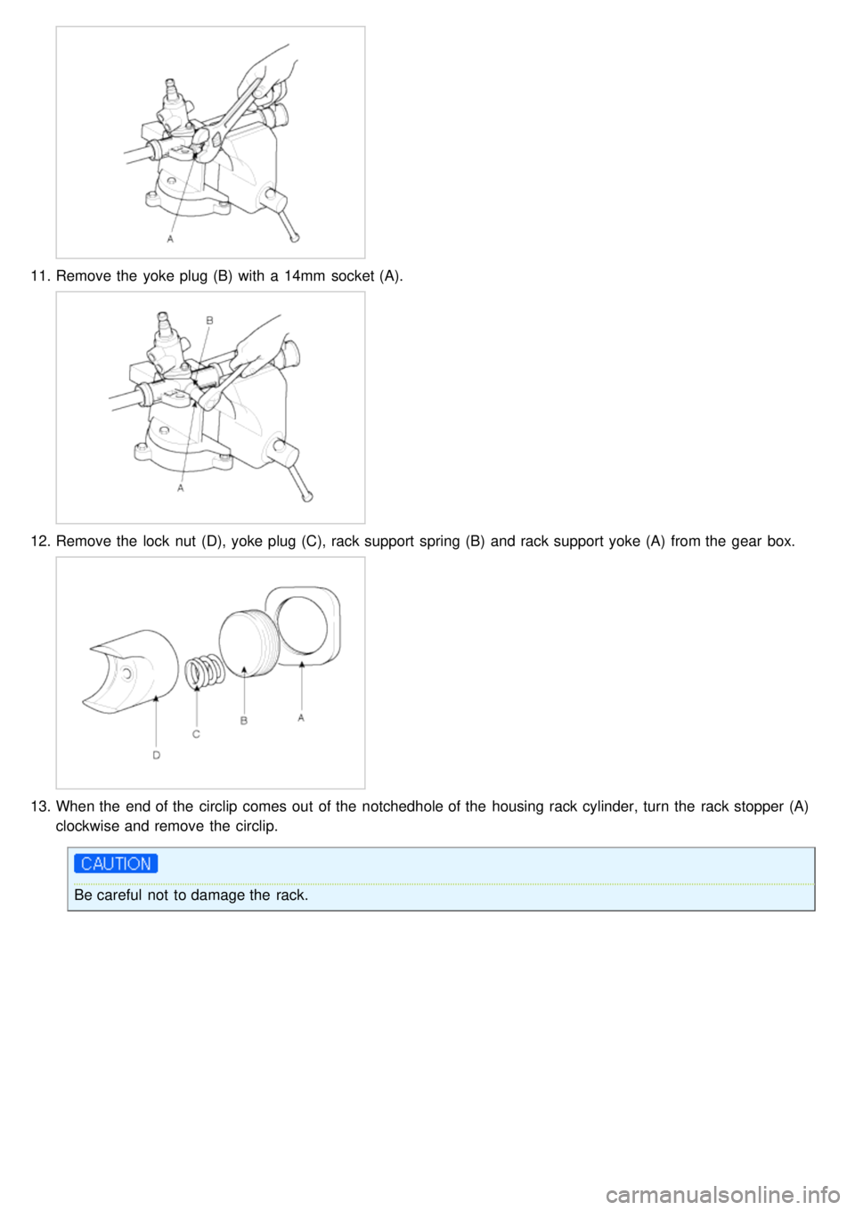
11.Remove the yoke plug (B) with a 14mm socket (A).
12.Remove the lock nut (D), yoke plug (C), rack support spring (B) and rack support yoke (A) from the gear box.
13.When the end of the circlip comes out of the notchedhole of the housing rack cylinder, turn the rack stopper (A)
clockwise and remove the circlip.
Be careful not to damage the rack.
Page 607 of 1575

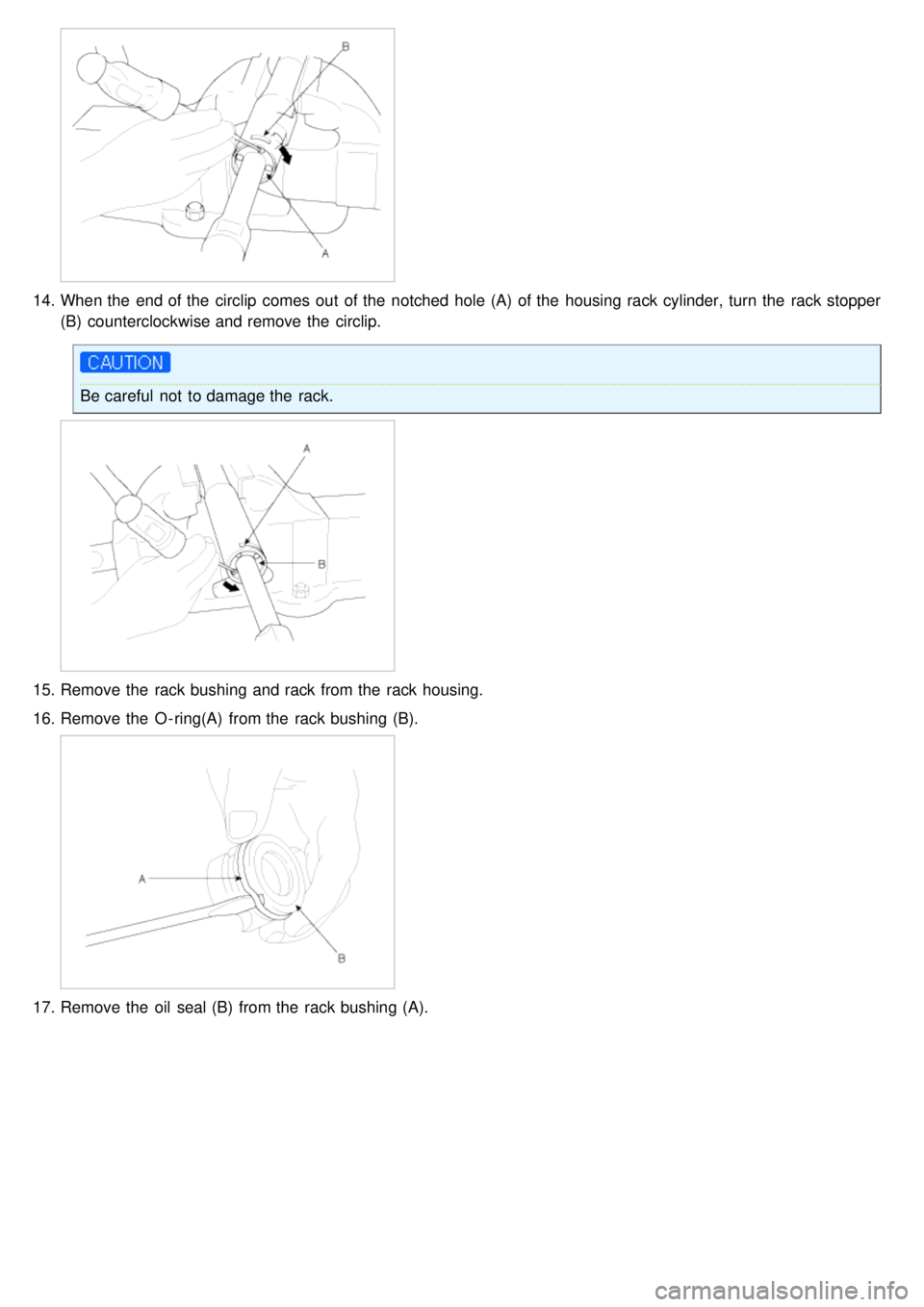
14.When the end of the circlip comes out of the notched hole (A) of the housing rack cylinder, turn the rack stopper
(B) counterclockwise and remove the circlip.
Be careful not to damage the rack.
15.Remove the rack bushing and rack from the rack housing.
16. Remove the O - ring(A) from the rack bushing (B).
17.Remove the oil seal (B) from the rack bushing (A).
Page 804 of 1575

2007 > 2.7L V6 GASOLINE >
COMPONENT REPLACEMENT AFTER DEPLOYMENT
Before doing any SRS repairs, use the Hi - Scan Pro to check for DTCs. Refer to the Diagnostic Trouble Code list
for repairing of the related DTCs.
When the front airbag(s) deployed after a collision, replace the following items. a. SRSCM
b. Deployed airbag(s)
c. Seat belt pretensioner(s)
d. Front impact sensors
e. SRS wiring harnesses
f. Inspect the clock spring for heat damage.
If any damage found, replace the clock spring.
When the seat belt pretensioner(s) deployed after a collision, replace the following items. a. Seat belt pretensioner(s)
b. SRSCM (if B1658 detected)
c. Front impact sensors
d. SRS wiring harnesses
When the side/curtain airbag(s) deployed after a collision, replace the following items. a. SRSCM
b. Deployed airbag(s)
c. Side impact sensor(s) for the deployed side(s)
d. SRS wiring harnesses
After the vehicle is completely repaired, confirm the SRS airbag system is OK. a. Turn the ignition switch ON, the SRS indicator should come on for about 6 seconds and then go off.
Page 832 of 1575

Drive Airbag (DAB) Module and
Clock Spring
Page 833 of 1575

2007 > 2.7L V6 GASOLINE >
DESCRIPTION
Driver Airbag (DAB) is installed in steering wheel and electrically connected to SRSCM via clockspring. It protects the
driver from danger by deploying a bag when frontal crash occurs. The SRSCM determines deployment of Driver Airbag
(DAB).
Never attempt to measure the circuit resistance of the airbag module (squib) even if you are using the specified
tester. If the circuit resistance is measured with a tester, accidental airbag deployment will result in serious
personal injury.
Page 835 of 1575

2007 > 2.7L V6 GASOLINE >
REMOVAL
1.Disconnect the battery negative cable and wait at least three minutes before beginning work.
2. Remove the airbag module mounting bolts.
3.Disconnect the horn connector(A).
4.Release the connector locking pin(B), then disconnect the driver airbag module connector(C).
The removed airbag module should be stored in a clean, dry place with the pad cover face up.
5. Remove the steering wheel and steering wheel column cover(Refer to ST group in the Workshop Manual).
6. Disconnect the clock spring and horn connector, then remove the clock spring.
INSTALLATION
1.Disconnect the negative ( - ) cable from battery and wait for at least three minutes.
Page 836 of 1575

2.Remove ignition key from the vehicle.
3. Connect the clock spring harness connetor and horn harness connector to the clock spring.
4. Set the clock spring on neutral position and after turning the front wheels to the straight- ahead position, install the
clock spring.
5. Install the steering wheel column cover and the steering wheel. (Refer to ST group)
6. Connect the Driver Airbag (DAB) module connector and horn connector, then install the Driver Airbag (DAB)
module on the steering wheel.
7. Secure the Driver Airbag (DAB) with the new mounting bolts.
Tightening Torque (DAB Mounting Bolt)
: 0.8 ~ 1.1 kgf.m (7.9 ~ 10.8 Nm, 5.8 ~ 8.0 lb.ft)
8.Connect the battery negative cable.
9. After installing the airbag, confirm proper system operation:
a. Turn the ignition switch ON; the SRS indicator light should be turned on for about six seconds and then go off.
b. Make sure horn button works.
INSPECTION
Driver Airbag (DAB)
If any improper parts are found during the following inspection, replace the airbag module with a new one.
Never attempt to measure the circuit resistance of the airbag module (squib) even if you are using the specified
tester. If the circuit resistance is measured with a tester, accidental airbag deployment will result in serious
personal injury.
1. Check pad cover for dents, cracks or deformities.
2. Check the airbag module for denting, cracking or deformation.
3. Check hooks and connectors for damage, terminals for deformities, and harness for binds.
Page 837 of 1575

4.Check airbag inflator case for dents, cracks or deformities.
5.Install the airbag module to the steering wheel to check for fit or alignment with the wheel.
Clockspring
1.If, as a result of the following checks, even one abnormal point is discovered, replace the clock spring with a new
one.
2. Check connectors and protective tube for damage, and terminals for deformities.
Page 950 of 1575

2007 > 2.7L V6 GASOLINE >
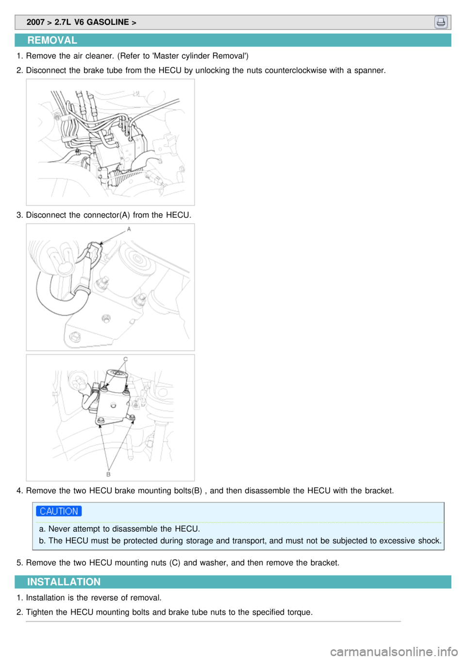
REMOVAL
1.Remove the air cleaner. (Refer to 'Master cylinder Removal')
2. Disconnect the brake tube from the HECU by unlocking the nuts counterclockwise with a spanner.
3.Disconnect the connector(A) from the HECU.
4.Remove the two HECU brake mounting bolts(B) , and then disassemble the HECU with the bracket.
a.Never attempt to disassemble the HECU.
b. The HECU must be protected during storage and transport, and must not be subjected to excessive shock.
5. Remove the two HECU mounting nuts (C) and washer, and then remove the bracket.
INSTALLATION
1.Installation is the reverse of removal.
2. Tighten the HECU mounting bolts and brake tube nuts to the specified torque.