ignition KIA CARNIVAL 2007 Workshop Manual
[x] Cancel search | Manufacturer: KIA, Model Year: 2007, Model line: CARNIVAL, Model: KIA CARNIVAL 2007Pages: 1575, PDF Size: 44.86 MB
Page 12 of 1575

2007 > 2.7L V6 GASOLINE >
Compression pressure inspection
If the there is lack of power, excessive oil consumption or poor fuel economy, measure the compression
pressure.
1. Warm up the engine until the normal operating temperature becoming 80~95°C(176~203°F).
2. Remove the surge tank.
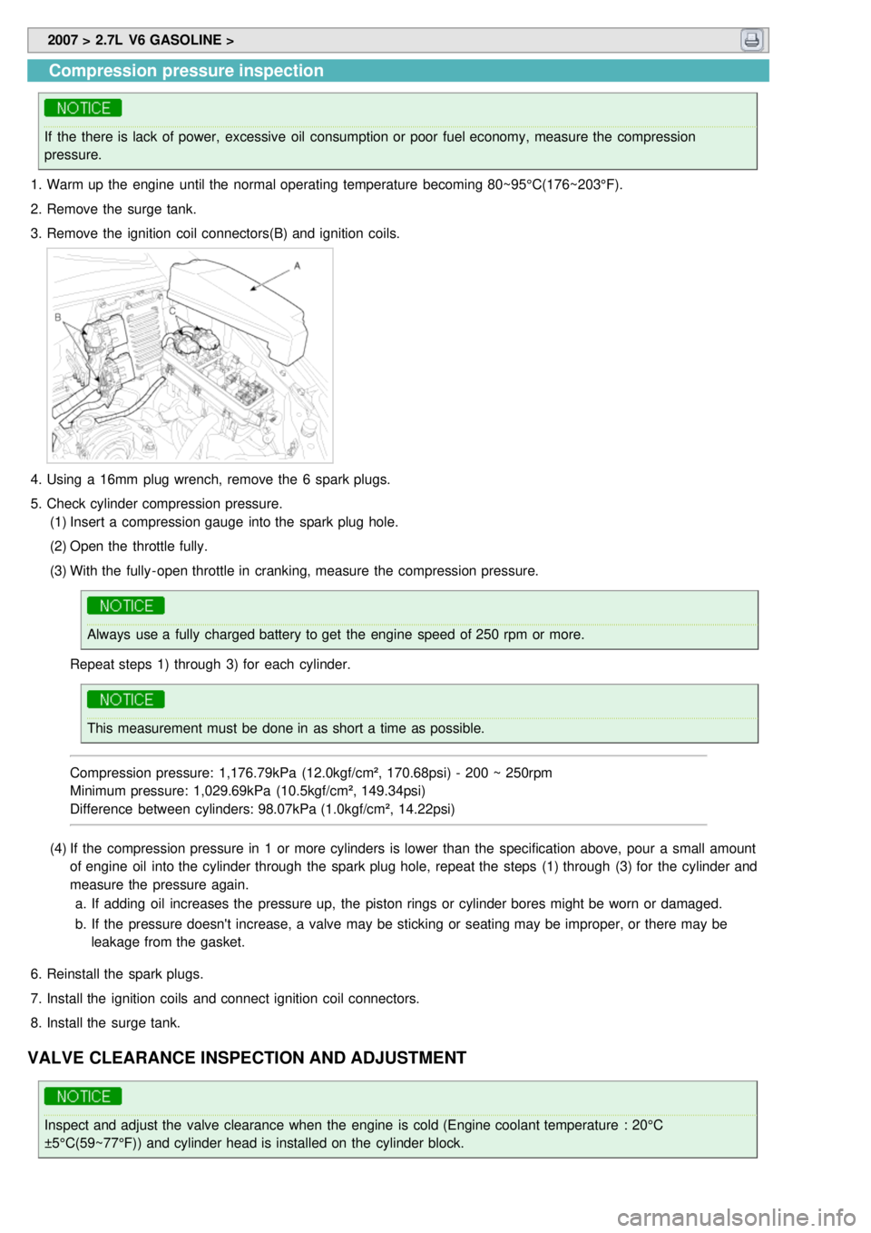
3. Remove the ignition coil connectors(B) and ignition coils.
4.Using a 16mm plug wrench, remove the 6 spark plugs.
5. Check cylinder compression pressure.
(1) Insert a compression gauge into the spark plug hole.
(2) Open the throttle fully.
(3) With the fully - open throttle in cranking, measure the compression pressure.
Always use a fully charged battery to get the engine speed of 250 rpm or more.
Repeat steps 1) through 3) for each cylinder.
This measurement must be done in as short a time as possible.
Compression pressure: 1,176.79kPa (12.0kgf/cm², 170.68psi) - 200 ~ 250rpm
Minimum pressure: 1,029.69kPa (10.5kgf/cm², 149.34psi)
Difference between cylinders: 98.07kPa (1.0kgf/cm², 14.22psi)
(4) If the compression pressure in 1 or more cylinders is lower than the specification above, pour a small amount
of engine oil into the cylinder through the spark plug hole, repeat the steps (1) through (3) for the cylinder and
measure the pressure again.
a. If adding oil increases the pressure up, the piston rings or cylinder bores might be worn or damaged.
b. If the pressure doesn't increase, a valve may be sticking or seating may be improper, or there may be
leakage from the gasket.
6. Reinstall the spark plugs.
7. Install the ignition coils and connect ignition coil connectors.
8. Install the surge tank.
VALVE CLEARANCE INSPECTION AND ADJUSTMENT
Inspect and adjust the valve clearance when the engine is cold (Engine coolant temperature : 20°C
±5°C(59~77°F)) and cylinder head is installed on the cylinder block.
Page 13 of 1575

1.Remove the engine cover.
2. Remove air cleaner assembly.
3. Remove the surge tank.
4. Remove the cylinder head cover.
(1) Disconnect the ignition coil connector and remove the ignition coil.
(2) Remove the cylinder head cover.
5.Set the piston of the No.1 cylinder to TDC(Top Dead Center) position.
(1) Turn the crankshaft pulley clockwise and align its groove with the timing mark "T" of the timing chain cover.
(2) Check that the timing marks of the camshaft sprocket are in straight line on that of the cylinder head cover
surface as shwn in the illustration. It makes the piston of the No.1 cylinder position at TDC.
If not, turn the crankshaft one revolution clockwise.
6. Inspect the intake and the exhaust valve clearance.
(1) With the piston of the No.1 cylinder positioning at TDC, the valves which can be measured its clearance are as
shown below.
Measurement method.
a. Using a thickness gauge, measure the clearance between the tappet and the base circle of camshaft.
b. Record the out - of- specification valve clearance measurements. They will be used later to determine the
required adjusting tappet for replacement.
Page 36 of 1575

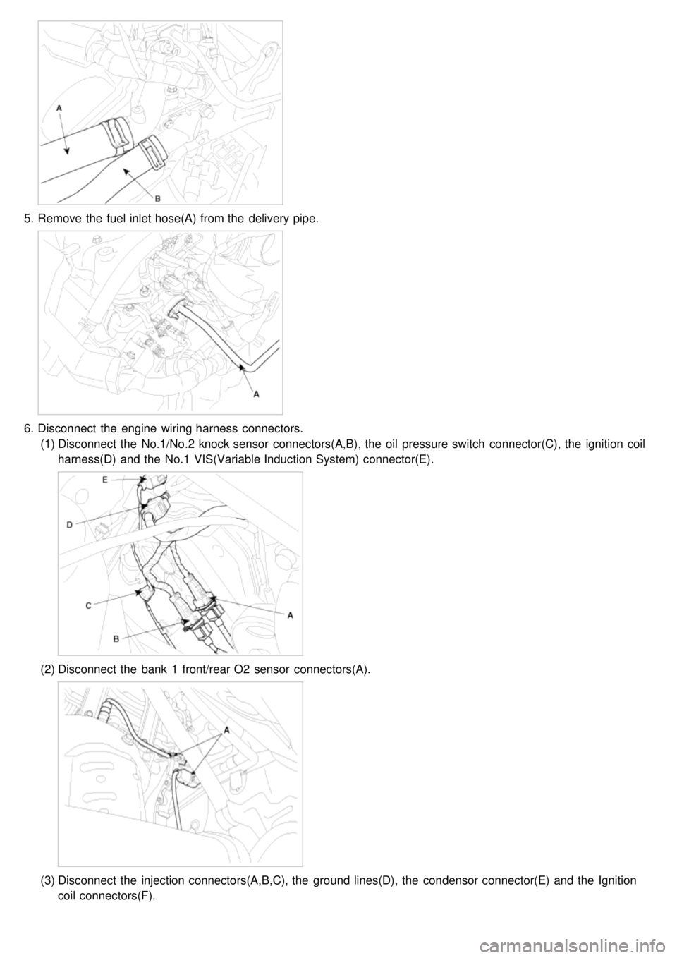
5.Remove the fuel inlet hose(A) from the delivery pipe.
6.Disconnect the engine wiring harness connectors.
(1) Disconnect the No.1/No.2 knock sensor connectors(A,B), the oil pressure switch connector(C), the ignition coil
harness(D) and the No.1 VIS(Variable Induction System) connector(E).
(2)Disconnect the bank 1 front/rear O2 sensor connectors(A).
(3)Disconnect the injection connectors(A,B,C), the ground lines(D), the condensor connector(E) and the Ignition
coil connectors(F).
Page 39 of 1575

8.Disconnect the brake vaccume hose(A).
9.Remove the heater hoses.
10. Remove the drive belt(A).
11.Remove the power steering pump.(Refer to 'ST' group).
12. Remove the exhaust manifold assembly.(Refer to 'Intake and exhause system').
13. Remove the intake manifold assembly.(Refer to 'Intake and exhause system').
14. Remove the timing belt.(Refer to 'Timing system').
15. Remove the ignition coils.
16. Remove the water temp. control assembly.
17. Remove the cylinder head cover(A).
Page 50 of 1575

(6)Connect the injection harness connector(A), the No.2 VIS(Variable Induction System) connector(B), the
No.1/No.2 OCV(Oil Control Valve) connectors(C,D) and the OTS(Oil Temperature Sensor) connector(E).
(7)Connect the injection connectors(A,B,C), the ground lines(D), the condensor connector(E) and the Ignition coil
connectors(F).
(8)Connect the bank 1 front/rear O2 sensor connectors(A).
Page 51 of 1575

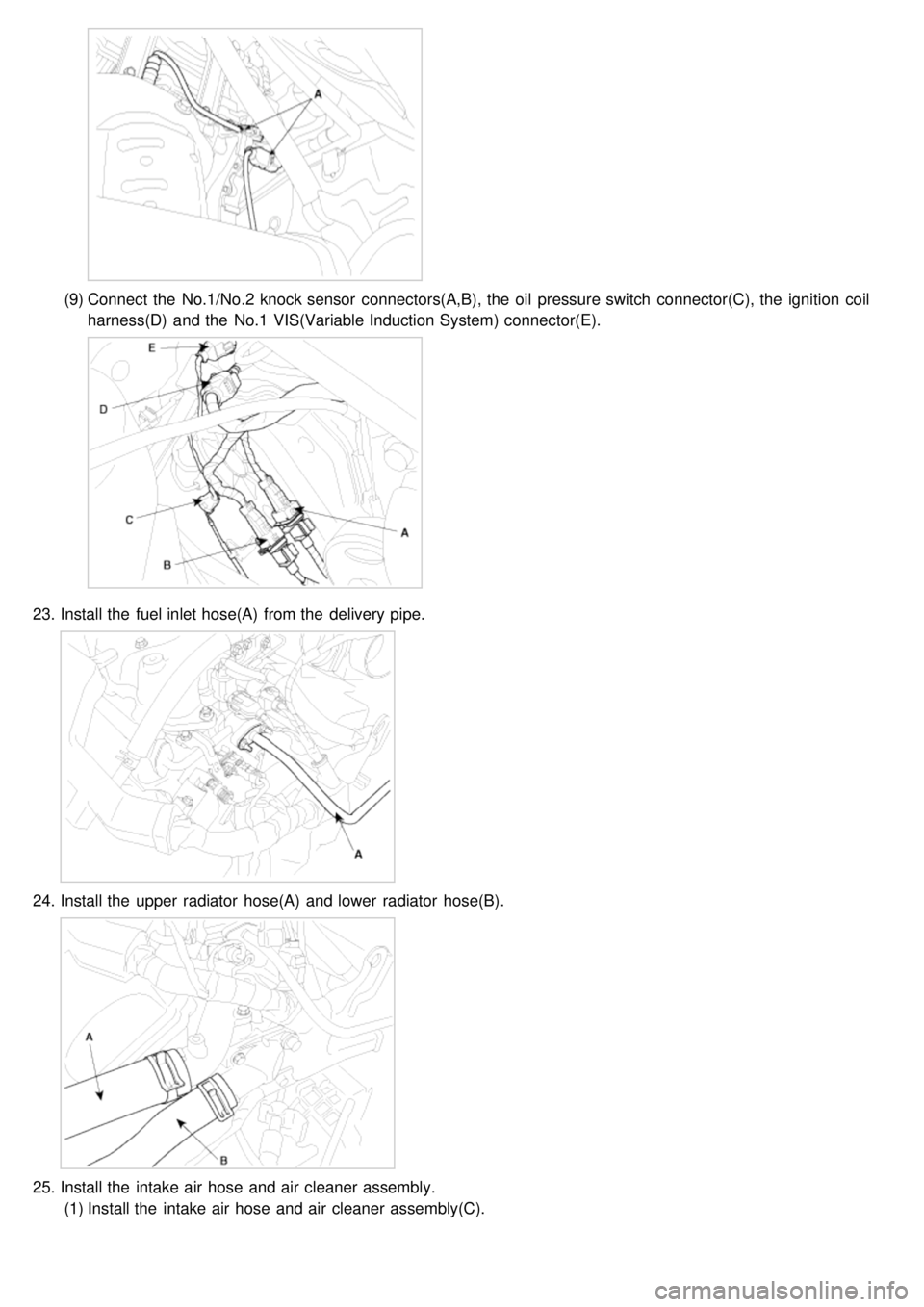
(9)Connect the No.1/No.2 knock sensor connectors(A,B), the oil pressure switch connector(C), the ignition coil
harness(D) and the No.1 VIS(Variable Induction System) connector(E).
23. Install the fuel inlet hose(A) from the delivery pipe.
24.Install the upper radiator hose(A) and lower radiator hose(B).
25.Install the intake air hose and air cleaner assembly.
(1) Install the intake air hose and air cleaner assembly(C).
Page 65 of 1575

(1)Disconnect the No.1/No.2 knock sensor connectors(A,B), the oil pressure switch connector(C), the ignition coil
harness(D) and the No.1 VIS(Variable Induction System) connector(E).
(2)Disconnect the bank 1 front/rear O2 sensor connectors(A).
(3)Disconnect the injection connectors(A,B,C), the ground lines(D), the condenser connector(E) and the Ignition
coil connectors(F).
(4)Disconnect the injection harness connector(A), the No.2 VIS(Variable Induction System) connector(B), the
No.1/No.2 OCV(Oil Control Valve) connectors(C,D) and the OTS(Oil Temperature Sensor) connector(E).
Page 71 of 1575

INSTALLATION
Installation is in the reverse order of removal.
Perform the following :a. Adjust the shift cable.
b. Refill the engine with engine oil.
c. Refill the transaxle with fluid.
d. Refill the radiator with engine coolant.
e. Bleed air from the cooling system with the heater valve open.
f. Clean the battery posts and cable terminals with sandpaper assemble them, then apply grease to prevent
corrosion.
g. Inspect for fuel leakage.
After assembling the fuel line, turn on the ignition switch (do not operate the starter) so that the fuel pump runs for
approximately two seconds and fuel line pressurizes.
Repeat this operation two or three times, then check for fuel leakage at any point in the fuel line.
Page 131 of 1575

2007 > 2.7L V6 GASOLINE >
REMOVAL
INTAKE MANIFOLD ASSEMBLY
1. Remove the engine cover.
2. Remove the intake air hose and air cleaner assembly.
(1) Disconnect the MAF connector(A).
(2) Disconnect the breather hose(B) from air cleaner hose.
(3) Remove the intake air hose and air cleaner assembly(C).
3.Disconnect the engine wiring harness connectors.
(1) Disconnect the No.1/No.2 knock sensor connectors(A,B), the oil pressure switch connector(C), the ignition coil
harness(D) and the No.1 VIS(Variable Induction System) connector(E).
(2)Disconnect the bank 1 front/rear O2 sensor connectors(A).
(3)Disconnect the injection connectors(A,B,C), the ground lines(D), the condensor connector(E) and the Ignition
coil connectors(F).
Page 149 of 1575

2007 > 2.7L V6 GASOLINE >
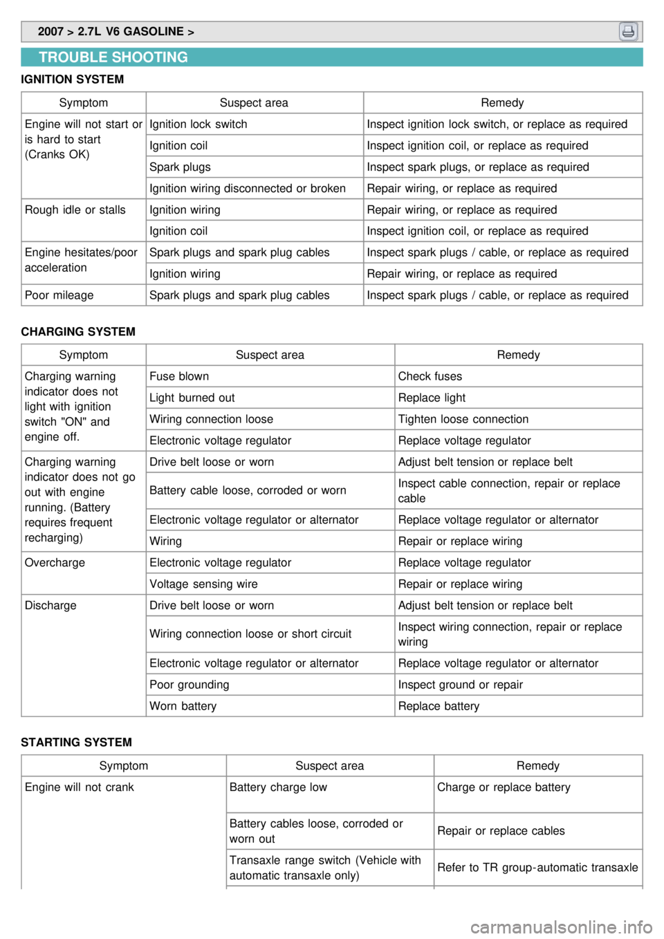
TROUBLE SHOOTING
IGNITION SYSTEM
Symptom Suspect area Remedy
Engine will not start or
is hard to start
(Cranks OK) Ignition lock switch
Inspect ignition lock switch, or replace as required
Ignition coil Inspect ignition coil, or replace as required
Spark plugs Inspect spark plugs, or replace as required
Ignition wiring disconnected or broken Repair wiring, or replace as required
Rough idle or stalls Ignition wiring Repair wiring, or replace as required
Ignition coil Inspect ignition coil, or replace as required
Engine hesitates/poor
acceleration Spark plugs and spark plug cables
Inspect spark plugs / cable, or replace as required
Ignition wiring Repair wiring, or replace as required
Poor mileage Spark plugs and spark plug cables Inspect spark plugs / cable, or replace as required
CHARGING SYSTEM Symptom Suspect area Remedy
Charging warning
indicator does not
light with ignition
switch "ON" and
engine off. Fuse blown
Check fuses
Light burned out Replace light
Wiring connection loose Tighten loose connection
Electronic voltage regulator Replace voltage regulator
Charging warning
indicator does not go
out with engine
running. (Battery
requires frequent
recharging) Drive belt loose or worn
Adjust belt tension or replace belt
Battery cable loose, corroded or worn Inspect cable connection, repair or replace
cable
Electronic voltage regulator or alternator Replace voltage regulator or alternator
Wiring Repair or replace wiring
Overcharge Electronic voltage regulator Replace voltage regulator
Voltage sensing wire Repair or replace wiring
Discharge Drive belt loose or worn Adjust belt tension or replace belt
Wiring connection loose or short circuit Inspect wiring connection, repair or replace
wiring
Electronic voltage regulator or alternator Replace voltage regulator or alternator
Poor grounding Inspect ground or repair
Worn battery Replace battery
STARTING SYSTEM Symptom Suspect area Remedy
Engine will not crank Battery charge low Charge or replace battery
Battery cables loose, corroded or
worn out Repair or replace cables
Transaxle range switch (Vehicle with
automatic transaxle only) Refer to TR group - automatic transaxle