clock KIA CARNIVAL 2007 Workshop Manual
[x] Cancel search | Manufacturer: KIA, Model Year: 2007, Model line: CARNIVAL, Model: KIA CARNIVAL 2007Pages: 1575, PDF Size: 44.86 MB
Page 13 of 1575

1.Remove the engine cover.
2. Remove air cleaner assembly.
3. Remove the surge tank.
4. Remove the cylinder head cover.
(1) Disconnect the ignition coil connector and remove the ignition coil.
(2) Remove the cylinder head cover.
5.Set the piston of the No.1 cylinder to TDC(Top Dead Center) position.
(1) Turn the crankshaft pulley clockwise and align its groove with the timing mark "T" of the timing chain cover.
(2) Check that the timing marks of the camshaft sprocket are in straight line on that of the cylinder head cover
surface as shwn in the illustration. It makes the piston of the No.1 cylinder position at TDC.
If not, turn the crankshaft one revolution clockwise.
6. Inspect the intake and the exhaust valve clearance.
(1) With the piston of the No.1 cylinder positioning at TDC, the valves which can be measured its clearance are as
shown below.
Measurement method.
a. Using a thickness gauge, measure the clearance between the tappet and the base circle of camshaft.
b. Record the out - of- specification valve clearance measurements. They will be used later to determine the
required adjusting tappet for replacement.
Page 14 of 1575
![KIA CARNIVAL 2007 Workshop Manual Specification
Limit (Engine coolant temperature : 20°C [68°F])
Intake : 0.10 ~ 0.30mm (0.0039 ~ 0.0118in.)
Exhaust : 0.20 ~ 0.40mm (0.0079 ~ 0.0157in.)
(2) Turn the crankshaft pulley one revo KIA CARNIVAL 2007 Workshop Manual Specification
Limit (Engine coolant temperature : 20°C [68°F])
Intake : 0.10 ~ 0.30mm (0.0039 ~ 0.0118in.)
Exhaust : 0.20 ~ 0.40mm (0.0079 ~ 0.0157in.)
(2) Turn the crankshaft pulley one revo](/img/2/57045/w960_57045-13.png)
Specification
Limit (Engine coolant temperature : 20°C [68°F])
Intake : 0.10 ~ 0.30mm (0.0039 ~ 0.0118in.)
Exhaust : 0.20 ~ 0.40mm (0.0079 ~ 0.0157in.)
(2) Turn the crankshaft pulley one revolution (360°) clockwise and align the groove with the timing mark "T" of the
timing chain cover.
(3) With the piston of the No.4 cylinder positioning at TDC, the valves which can be measured its clearance are as
shown below.
7.Adjust the intake and the exhaust valve clearances.
(1) Set the piston of the No.1 cylinder to the TDC/position.
(2) Remove the timing belt.
(3) Remove the camshaft bearing caps(A, B).
(4)Remove the camshaft assembly.
(5) Remove MLA(Mechanical Lash Adjuster)s.
(6) Measure the thickness of the removed tappet using a micrometer.
(7)Calculate the thickness of a new tappet so that the valve clearance comes within the specified value.
T : Thickness of removed tappet
A : Measured valve clearance
Page 15 of 1575
![KIA CARNIVAL 2007 Workshop Manual N : Thickness of new tappet
Intake : N = T + [A - 0.20mm(0.0079in.)]
Exhaust : N = T + [A - 0.30mm (0.0118in.)]
(8) Select a new tappet with a thickness as close as possible to the calculat KIA CARNIVAL 2007 Workshop Manual N : Thickness of new tappet
Intake : N = T + [A - 0.20mm(0.0079in.)]
Exhaust : N = T + [A - 0.30mm (0.0118in.)]
(8) Select a new tappet with a thickness as close as possible to the calculat](/img/2/57045/w960_57045-14.png)
N : Thickness of new tappet
Intake : N = T + [A - 0.20mm(0.0079in.)]
Exhaust : N = T + [A - 0.30mm (0.0118in.)]
(8) Select a new tappet with a thickness as close as possible to the calculated value.
Tappets are available with 41different size increments of 0.015mm (0.0006in.) from 3.00mm (0.118in.) to
3.600mm (0.1417in.)
(9) Place a new tappet on the cylinder head.
Apply engine oil on the periphery surface of the selected tappet.
(10) Install the intake and exhaust camshafts.
(11) Install the bearing caps.
(12) Install the timing belt.
(13) Turn the crankshaft two revolutions in the operating direction(clockwise) and realign crankshaft sprocket and
camshaft sprocket timing marks(A).
(14) Recheck the valve clearance.
Specification (Engine coolant temperature: 20°C[68°F])
Intake : 0.17 ~ 0.23mm (0.0067 ~ 0.0090in.)
Exhaust : 0.27 ~ 0.33mm (0.0106 ~ 0.0129in.)
Page 23 of 1575

2007 > 2.7L V6 GASOLINE >
REMOVAL
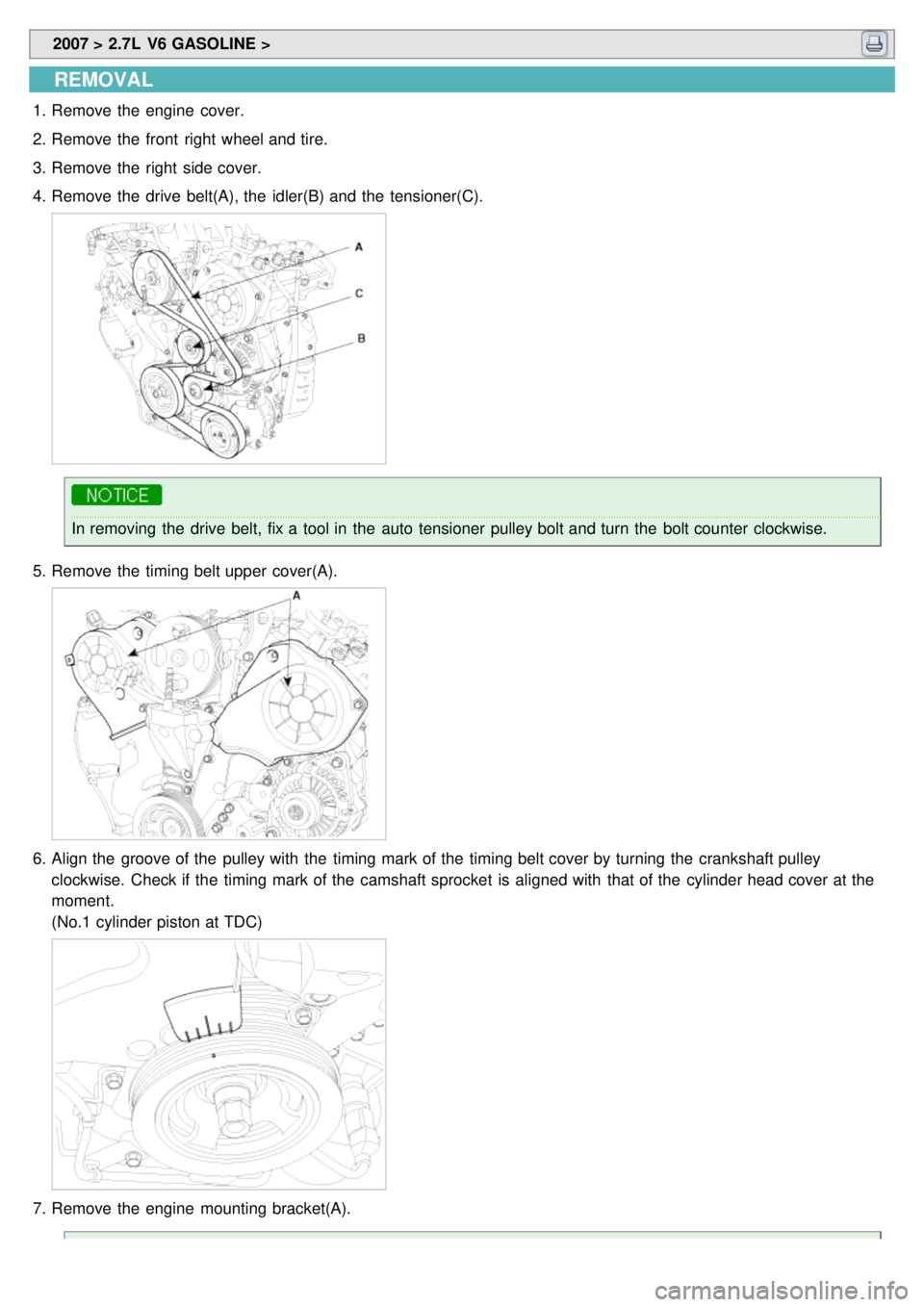
1.Remove the engine cover.
2. Remove the front right wheel and tire.
3. Remove the right side cover.
4. Remove the drive belt(A), the idler(B) and the tensioner(C).
In removing the drive belt, fix a tool in the auto tensioner pulley bolt and turn the bolt counter clockwise.
5. Remove the timing belt upper cover(A).
6.Align the groove of the pulley with the timing mark of the timing belt cover by turning the crankshaft pulley
clockwise. Check if the timing mark of the camshaft sprocket is aligned with that of the cylinder head cover at the
moment.
(No.1 cylinder piston at TDC)
7.Remove the engine mounting bracket(A).
Page 28 of 1575

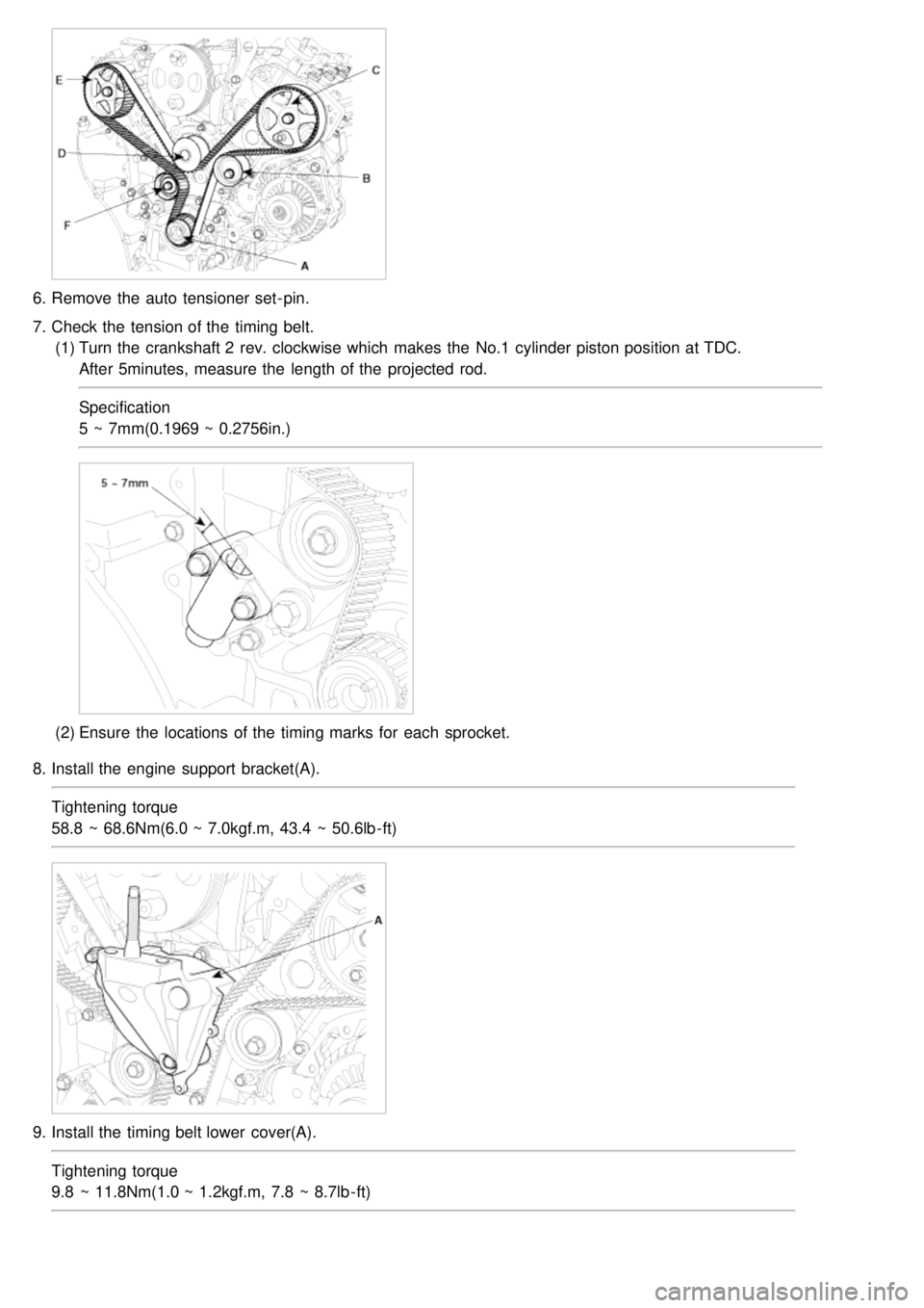
6.Remove the auto tensioner set- pin.
7. Check the tension of the timing belt.
(1) Turn the crankshaft 2 rev. clockwise which makes the No.1 cylinder piston position at TDC.
After 5minutes, measure the length of the projected rod.
Specification
5 ~ 7mm(0.1969 ~ 0.2756in.)
(2)Ensure the locations of the timing marks for each sprocket.
8. Install the engine support bracket(A).
Tightening torque
58.8 ~ 68.6Nm(6.0 ~ 7.0kgf.m, 43.4 ~ 50.6lb- ft)
9.Install the timing belt lower cover(A).
Tightening torque
9.8 ~ 11.8Nm(1.0 ~ 1.2kgf.m, 7.8 ~ 8.7lb - ft)
Page 44 of 1575

camshaft. Ensure that the pin will not be installed in the hole for oil feeding.
Tightening torque
66.7~78.5Nm(6.8~8.0kgf.m, 49.2~57.9lb - ft)
After tightening the CVVT bolts, rotate the CVVT assembly housing counterclockwise by hand to seat the lock
pin in the CVVT assembly in good position.
Fix the hexagonal part of the camshaft in a vice when tightening the CVVT bolts. Do not fix the CVVT housing
or sprocket in a vice.
4. Install the camshaft in the cylinder head assembly.
(1) Align the timing mark of the camshaft timinig chain.
LH camshaft chain timing mark
RH camshaft chain timing mark
Both timing marks should face upward in reassemby.
5. Install the timing chain tensioner.
(1) Insert the set pin by pressing the timing chain tensioner.
(2) Install the chain tensioner(A) in the cylinder head assembly.
Page 339 of 1575

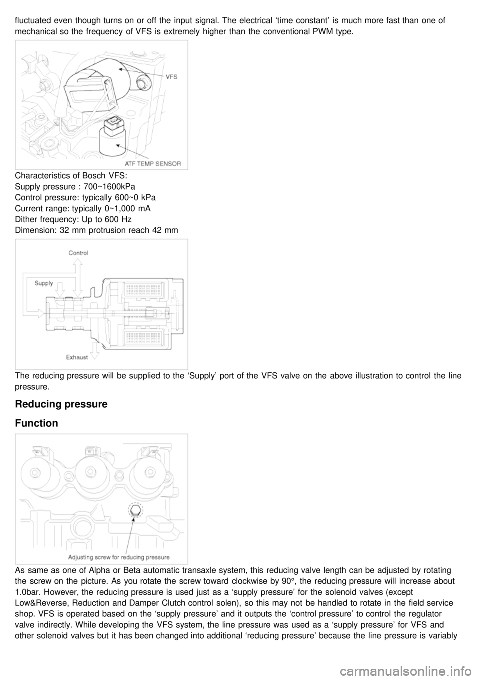
fluctuated even though turns on or off the input signal. The electrical ‘time constant’ is much more fast than one of
mechanical so the frequency of VFS is extremely higher than the conventional PWM type.
Characteristics of Bosch VFS:
Supply pressure : 700~1600kPa
Control pressure: typically 600~0 kPa
Current range: typically 0~1,000 mA
Dither frequency: Up to 600 Hz
Dimension: 32 mm protrusion reach 42 mm
The reducing pressure will be supplied to the ‘Supply’ port of the VFS valve on the above illustration to control the line
pressure.
Reducing pressure
Function
As same as one of Alpha or Beta automatic transaxle system, this reducing valve length can be adjusted by rotating
the screw on the picture. As you rotate the screw toward clockwise by 90°, the reducing pressure will increase about
1.0bar. However, the reducing pressure is used just as a ‘supply pressure’ for the solenoid valves (except
Low&Reverse, Reduction and Damper Clutch control solen), so this may not be handled to rotate in the field service
shop. VFS is operated based on the ‘supply pressure’ and it outputs the ‘control pressure’ to control the regulator
valve indirectly. While developing the VFS system, the line pressure was used as a ‘supply pressure’ for VFS and
other solenoid valves but it has been changed into additional ‘reducing pressure’ because the line pressure is variably
changed by VFS so the control pressure becomes unstable and some hydraulic pressure oscillation occurred. That is
Page 573 of 1575
![KIA CARNIVAL 2007 Workshop Manual [REAR]
Standard value :
Toe- in (B- A) mm (in) : 2.6 ± 2 (0.1024 ± 0.0787)
Adjust the toe - in by turning the cambolt of the assist arm.
Left cambolt : Clockwise → toe - in
Right camb KIA CARNIVAL 2007 Workshop Manual [REAR]
Standard value :
Toe- in (B- A) mm (in) : 2.6 ± 2 (0.1024 ± 0.0787)
Adjust the toe - in by turning the cambolt of the assist arm.
Left cambolt : Clockwise → toe - in
Right camb](/img/2/57045/w960_57045-572.png)
[REAR]
Standard value :
Toe- in (B- A) mm (in) : 2.6 ± 2 (0.1024 ± 0.0787)
Adjust the toe - in by turning the cambolt of the assist arm.
Left cambolt : Clockwise → toe - in
Right cambolt : Clockwise → toe - out
The variation of toe by a rotation of the cambolt :
About 3.2 mm (0.126 in)
a. Each toe should be within ±1 mm (± 0.039 in).
If the difference between right and left is not within +2mm (0.079 in), repeat adjustment.
b. After adjusting the cambolt, tighten the nut to the specified torque.
Specified torque
90 ~ 120 Nm (9 ~ 12 kgf.m, 65.1 ~ 86.8 lb - ft)
CAMBER
[FRONT]
Camber is the inward or outward tilting of the wheels at the top.
Page 574 of 1575

ItemDescription
A Positive camber angle
B True vertical
When the wheel tilts out at the top, then the camber is positive (+).
When the wheel tilts in at the top, then the camber is negative(- ).
Standard value : 0° ± 30´
Difference between right and left angle is within 0° 30´
Camber is pre- set at the factory and doesn't need to be adjusted. If the camber is not within the standard value,
replace the bent or damaged parts.
[REAR]
Standard value : - 6´ ± 30´
Difference between right and left angle is within 0° 30´
Adjust the camber by turning the cambolt of the rear upper arm.
Left cambolt : Clockwise → camber(- )
Right cambolt : Clockwise →camber(+)
The variation of camber by a rotation of the cambolt :
About 0°8´35´´
CASTER
Caster is the tilting of the strut axis either forward or backward from vertical. A backward tilt is positive (+) and a
forward tilt is negative ( - ).
Caster is pre- set at the factory and doesn't need to be adjusted. If the caster is not within the standard value, replace
the bent or damaged parts.
Page 584 of 1575

CHECKING POWER STEERING BELT TENSION
Refer to EM group(Timing system).
CHECKING POWER STEERING FLUID LEVEL
1.Position the vehicle on a level surface.
2. Start the engine. With the vehicle kept stationary, turn the steering wheel several times continuously to raise the
fluid temperature to 50- 60°C (122 - 140°F).
3. With the engine at idle, turn the steering wheel fully clockwise and counter- clockwise several times.
4. Make sure that there is no foaming or cloudiness in the reservoir fluid.
5. Stop the engine and check for any difference in fluid level between a stationary and a running engine.
a.If the fluid level varies 5 mm (0.2 in) or more, bleed the system again.
b. If the fluid level suddenly rises after stopping the engine, further bleeding is required.
c. Incomplete bleeding will produce a chattering sound in the pump and noise in the flow control valve, and
lead to decreased durability of the pump.
REPLACING POWER STEERING FLUID
1.Jack up the front wheels and support them with jackstands.
2. Disconnect the return hose from the oil reservoir and plug the oil reservoir.
3. Connect a vinyl hose to the disconnected return hose, and drain the oil into a container.
4. Remove the fuel pump fuse, then start the engine and wait for the engine to stall. Next, while operating the starting
motor intermittently, turn the steering wheel all the way to the left and then to the right several times to drain the
fluid.
5. Connect the return hoses, then fill the oil reservoir with the specified fluid.
6. Reinstall the fuel pump fuse.
7. Start the engine. Check for oil leakage.
8. Stop the engine.
9. Bleed the system.
Power steering fluid type : PSF - 3
Total quantity : Approx 1.1 liter
AIR BLEEDING
1.Remove the fuel pump fuse, then start the engine and wait for the engine to stall. Next, while operating the starting
motor intermittently (for 15 ~ 20 seconds), turn the steering wheel all the way to the left and then to the right five or
six times.