ESP KIA CARNIVAL 2007 Owner's Guide
[x] Cancel search | Manufacturer: KIA, Model Year: 2007, Model line: CARNIVAL, Model: KIA CARNIVAL 2007Pages: 1575, PDF Size: 44.86 MB
Page 975 of 1575

The active EBD warning lamp module indicates the self - test and failure status of the EBD. However, in case the
Parking Brake Switch is turned on, the EBD warning lamp is always turned on regardless of EBD functions. The EBD
warning lamp shall be on:a. During the initialization phase after IGN ON. (continuously 3 seconds).
b. When the Parking Brake Switch is ON or brake fluid level is low.
c. When the EBD function is out of order .
d. During diagnostic mode.
e. When the ECU Connector is seperated from ECU.
ESP Warning Lamp (ESP system)
The ESP warning lamp indicates the self - test and failure status of the ESP.
The ESP warning lamp is turned on under the following conditions :
a. During the initialization phase after IGN ON. (continuously 3 seconds).
b. In the event of inhibition of ESP functions by failure.
c. When driver turn off the ESP function by on/off switch.
d. During diagnostic mode.
ESC Function Lamp (ESC system)
The ESP function lamp indicates the self - test and operating status of the ESP.
The ESP Function lamp operates under the following conditions :
a. During the initialization phase after IGN ON. (continuously 3 seconds).
b. When the ESP control is operating. (Blinking - 2Hz)
ESP On/Off Switch (ESP system)
The ESP On/Off Switch shall be used to toggle the ESP function between On/Off states based upon driver input.
The On/Off switch shall be a normally open, momentary contact switch.
Initial status of the ESP function is on and the switch is used to request an ESC status change.
Page 977 of 1575

2007 > 2.7L V6 GASOLINE >
FAILURE DIAGNOSIS
1.In principle, ESP and TCS controls are prohibited in case of ABS failure.
2. When ESP or TCS fails, only the failed system control is prohibited.
3. However, when the solenoid valve relay should be turned off in case of ESP failure, refer to the ABS fail- safe.
4. Information on ABS fail- safe is identical to the fail- safe in systems where ESP is not installed.
MEMORY OF FAIL CODE
1.It keeps the code as far as the backup lamp power is connected. (O)
2. It keeps the code as long as the HCU power is on. (X)
FAILURE CHECKUP
1.Initial checkup is performed immediately after the HECU power on.
2. Valve relay checkup is performed immediately after the IG2 ON.
3. It executes the checkup all the time while the IG2 power is on.
4. Initial checkup is made in the following cases.
(1) When no failure is detected
(2) When ABS and ESP are not in control.
(3) Initial checkup is not made after ECU power on.
(4) If the vehicle speed is over 5 mph(8 km/h) when the brake lamp switch is off.
(5) When the vehicle speed is over 24.8 mph(40 km/h).
5. Though, it keeps on checkup even if the brake lamp switch is on.
6. When performing ABS or ESP control before the initial checkup, stop the initial checkup and wait for the HECU
power input again.
7. Judge failure in the following cases.
(1) When the power is normal.
(2) From the point in which the vehicle speed reaches 4.9 mph(8 km/h) after HECU power on.
COUNTERMEASURES IN FAIL
1.Shut the system down and perform the following actions and wait for HECU power OFF.
2. Turn the valve relay off.
3. Do not perform any ABS/TCS/ESC functions until normal operating condition is restored.
WARNING LAMP ON
1.ABS warning lamp turns on when ABS is malfunctioning.
2. ESP operation lamp turns on when ESP is malfunctioning.
When power voltage and valve relay voltage are abnormal, input/output related failure judgment is not made.
Page 979 of 1575

2007 > 2.7L V6 GASOLINE >
DESCRIPTION
1.The yaw - rate & lateral G sensor is applied for the ESP system.
2. The yaw - rate is the angular velocity, when a vehicle turns a corner, and the lateral G is the acceleration to move a
vehicle out of the way when cornering.
3. The sensor is located in the crash pad lower floor on vehicle.
SPECIFICATION
Description SpecificationRemark
Nominal supply voltage 11.5 ~ 12.5 V
Supply voltage range 8 ~ 16 V
Supply current Max. 120 mATyp. 75 mA
Reference Voltage Output 2.464 ~ 2.536 VTyp. 2.5 V
Operating temperature range - 40 ~ 85°C
Yaw - late sensor Measurement range+w direction, left turn
Min.100 °/sTyp. 111 °/S
- w direction, right turn Min.100 °/sTyp. 111 °/S
Non- linearity - 1 ~ 1 %
Offset (within life,within operating temperature) 3.75 °/S
Upper cut- off frequency Min. 45 HzTyp. 60 Hz
Lateral G sensor Measurement range+y direction, left turn
Min.1.8 gTyp. 2 g
- y direction, right turn Min. - 1.8 gTyp. 2 g
Non- linearity - 4 ~ 4 %
Offset (within life,within operating temperature) - 0.09 ~ 0.09 g
Upper cut- off frequency Min. 20 HzTyp. 40 Hz
OUTPUT CHARACTERISTIC
Page 981 of 1575

ESP OFF Switch
Page 982 of 1575

2007 > 2.7L V6 GASOLINE >
DESCRIPTION
1.The ESP OFF switch is for the user to turn off the ESP system.
2. The ESP OFF lamp is on when ESP OFF switch is engaged.
Page 984 of 1575

2007 > 2.7L V6 GASOLINE >
INSPECTION
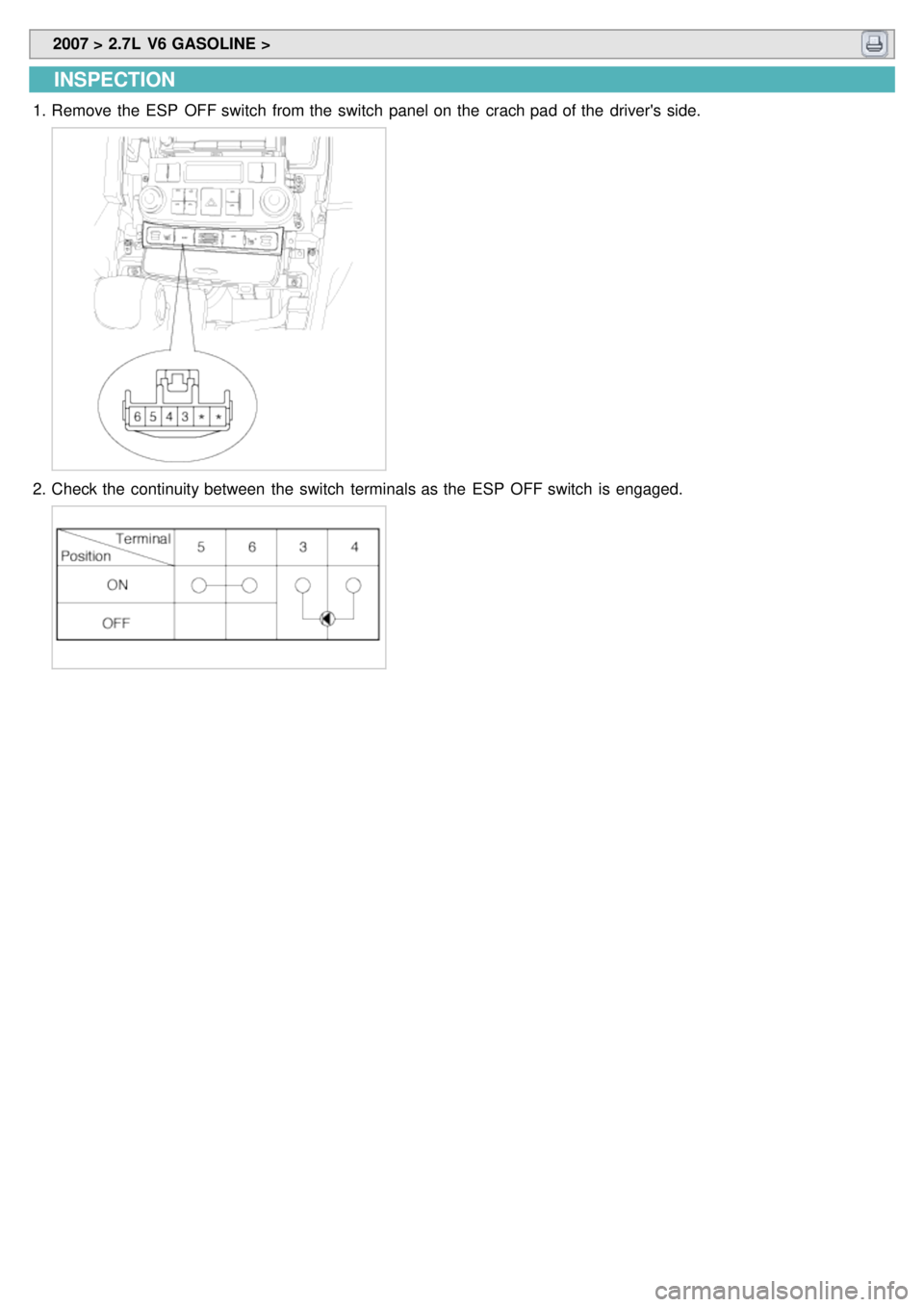
1.Remove the ESP OFF switch from the switch panel on the crach pad of the driver's side.
2.Check the continuity between the switch terminals as the ESP OFF switch is engaged.
Page 986 of 1575

2007 > 2.7L V6 GASOLINE >
DESCRIPTION
GENERAL DATA
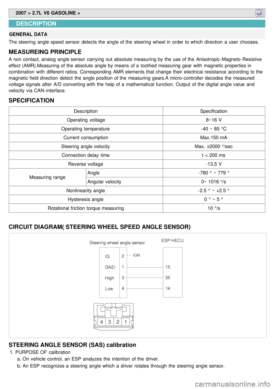
The steering angle speed sensor detects the angle of the steering wheel in order to which direction a user chooses.
MEASUREING PRINCIPLE
A non contact, analog angle sensor carrying out absolute measuring by the use of the Anisotropic - Magneto- Resistive
effect (AMR).Measuring of the absolute angle by means of a toothed measuring gear with magnetic properties in
combination with different ratios. Corresponding AMR elements that change their electrical resistance according to the
magnetic field direction detect the angle position of the measuring gears.A micro- controller decodes the measured
voltage signals after A/D converting with the help of a mathematical function. Output of the digital angle value and
velocity via CAN- interface.
SPECIFICATION
Description Specification
Operating voltage 8~16 V
Operating temperature - 40 ~ 85 °C
Current consumption Max.150 mA
Steering angle velocity Max. ±2000 °/sec
Connection delay time t < 200 ms
Reverse voltage - 13.5 V
Measuring range Angle
- 780 ° ~ 779 °
Angular velocity 0~ 1016 °/s
Nonlinearity angle - 2.5 ° ~ +2.5 °
Hysteresis angle 0 ° ~ 5 °
Rotational friction torque measuring 10 °/s
CIRCUIT DIAGRAM( STEERING WHEEL SPEED ANGLE SENSOR)
STEERING ANGLE SENSOR (SAS) calibration
1.PURPOSE OF calibration
a. On vehicle control, an ESP analyzes the intention of the driver.
b. An ESP recognizes a steering angle which a driver rotates through the steering angle sensor.
Page 987 of 1575

c.A steering angle sensor used in ESP adjusts 0° setting of steering wheel through K- line or CAN
communication.
2. STEERING ANGLE SENSOR (SAS) CALIBRATION METHOD
(1) Align the wheel to the straight line. (steering wheel < ± 5° )
ex) Perform the wheel alignment first.
Align the wheel to the straight line.
A driver moves the vehicle to the front and back about 5 meters twice or three times.
(2) Connect Scan tool to the vehicle.
(3) Select Brake system.
(4) Select Steering angle sensor(SAS) calibration.
(5)Perform the Steering angle sensor(SAS) calibration.
(6)Perform the procedure continuously.
Page 1154 of 1575

HANDLING WIRES AND HARNESSES
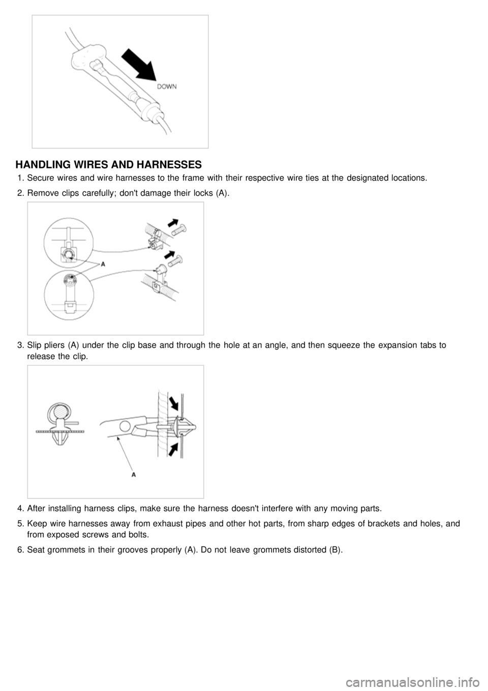
1.Secure wires and wire harnesses to the frame with their respective wire ties at the designated locations.
2. Remove clips carefully; don't damage their locks (A).
3.Slip pliers (A) under the clip base and through the hole at an angle, and then squeeze the expansion tabs to
release the clip.
4.After installing harness clips, make sure the harness doesn't interfere with any moving parts.
5. Keep wire harnesses away from exhaust pipes and other hot parts, from sharp edges of brackets and holes, and
from exposed screws and bolts.
6. Seat grommets in their grooves properly (A). Do not leave grommets distorted (B).
Page 1216 of 1575

Stop Lamps Function
1.Necessary conditions to switch ON the stop lamps:
a. Pushing on the brake pedal.
2. Necessary conditions to switch OFF the stop lamps:
a. Releasing the brake pedal.
3. Functional diagram
Auto Light Function
1.The Auto light function is active when the Head lamp switch is positioned to 'Auto' and the Key is in RUN position.
The auto light sensor is powered on the status ACC, START and RUN of the key position. Based on the Auto light
sensor values corresponding to the exterior brightness level, it controls automatically the lighting of the Park and tail
lamps or / and the Head lamps Low Beam depending on the country.
2. Auto light Sensor detection table
Mode Tail Lamps
Head Lamps Low Beam
Lux (Lux) Voltage(V) Lux (Lux)Voltage(V)
ON < 24 ± 5.2 <1.77 ± 0.08V Same as Tail lamps
OFF > 48 ± 10.5 > 3.47 ± 0.1V Same as Tail lamps
Drl Function
1.The Auto DRL function operates the Head lamps High Beam at 50% of full illumination.
The park and tail are managed by the auto light sensor.
The Auto DRL function is active if:
a. The ignition switch is on RUN position
b. The engine is running.
c. The Park brake switch is OFF.
2. The DRL function is inactive when one of above conditions is released.
When the DRL function is active, the Head lamps High Beam can't be turned ON, except for the Flash To Pass
activation.