IPM KIA CARNIVAL 2007 Owner's Guide
[x] Cancel search | Manufacturer: KIA, Model Year: 2007, Model line: CARNIVAL, Model: KIA CARNIVAL 2007Pages: 1575, PDF Size: 44.86 MB
Page 1261 of 1575

MEMORY STORAGE OPERATION BY KEYLESS
1.If "ID1" or "ID2" is received during keyless lock operation, record seat and pedal position in keyless code. (there is
no buzzer output during memory storage operation by keyless)
2. Memory storage operation is allowed for a single ID after a change of IG from "on" →"off".
3. Any one of the following conditions will prevent keyless Memory storage operation.
a. When "P" position switch is not on.
b. When Vehicle Speed in CAN BUS data transmitted from CLUSTER is "3km/h" or faster.
c. When seat and pedal is manipulated by CAN BUS and manual switch.
d. When IG transmitted from IPM is other than off.
PRESET RECALL OPERATION BY KEYLESS
1.When IG is off (CAN BUS data IG transmitted from IPM is "off") and a key is removed (CAN BUS data Key
Reminder Switch transmitted from IPM is "off"), and if "ID1" or "ID2" is received during keyless unlock operation, it
automatically adjusts seat and pedal positions as memorized in keyless code (there is no buzzer output during
preset recall operation by keyless). However, seat slide adjustment position is determined as follows, depending on
Auto switch.
a. When auto switch is on ("IMS Auto Switch" is "on") , the position is automatically adjusted to 50 mm farther
back than target position, and if a key is inserted ("Key Reminder Switch" changes from "off" to "on"), it
conducts Get- on gearing operation to a target preset recall position.
b. If auto switch is off ("IMS Auto Switch" is "off"), it moves to the target memory play position.
2. Any one of the following conditions will prevent preset recall operation.
a. When "P" position switch is not on.
b. When Vehicle Speed in CAN BUS data transmitted from cluster is "3km/h" or faster.
c. When seat and pedal is manipulated by CAN BUS and manual switch.
d. When IG Switch transmitted from IPM is other than off.
e. When a key is inserted.
3. Playing will be halted during preset recall operation if any of the following conditions is met.
a. When "P" position switch is not on.
b. When vehicle speed in CAN BUS data transmitted from cluster is "3km/h" or faster.
c. When seat and pedal is manipulated by CAN BUS and manual switch.
SETTING LIMIT
1.A limit switch is installed to prevent the seat from traveling beyond the maximum forward/reward positions.
2. No limit switch is installed for the recline, height, or pedal adjustments. Arbitrary limit positions are used for these
functions.
DETECTING ERRORS FOR SEAT
Take countermeasure against error if the following conditions occur during manual switch operation.
a. Error when pulse is not fed.
SlideReclineFront height Rear height
Page 1294 of 1575
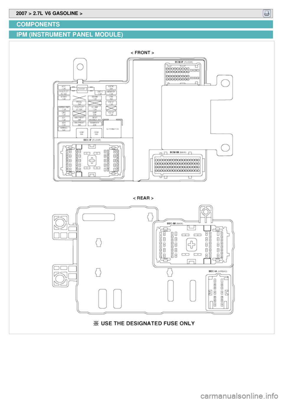
2007 > 2.7L V6 GASOLINE >
COMPONENTS
IPM (INSTRUMENT PANEL MODULE)
Page 1298 of 1575
2007 > 2.7L V6 GASOLINE >
INSPECTION
FUSE
1. Be sure there is no play in the fuse holders, and that the fuses are held securely.
2. Are the fuse capacities for each circuit correct?
3. Are there any blown fuses ?
If a fuse is to be replaced, be sure to use a new fuse of the same capacity. Always determine why the fuse blew
first and completely eliminate the problem before installing a new fuse.
RELAY
1.Be sure that the relays are held the each module securely.
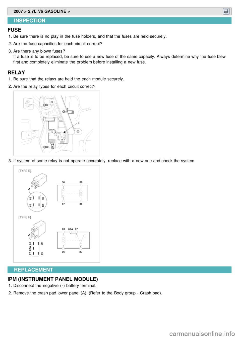
2. Are the relay types for each circuit correct?
3.If system of some relay is not operate accurately, replace with a new one and check the system.
REPLACEMENT
IPM (INSTRUMENT PANEL MODULE)
1. Disconnect the negative ( - ) battery terminal.
2. Remove the crash pad lower panel (A). (Refer to the Body group - Crash pad).
Page 1299 of 1575
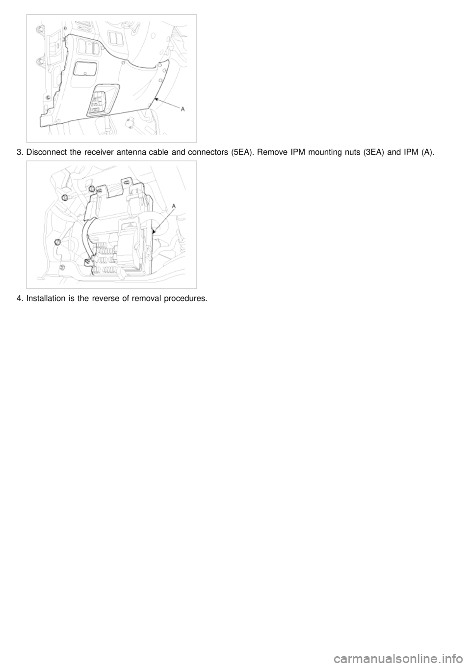
3.Disconnect the receiver antenna cable and connectors (5EA). Remove IPM mounting nuts (3EA) and IPM (A).
4.Installation is the reverse of removal procedures.
Page 1354 of 1575
2007 > 2.7L V6 GASOLINE >
INSPECTION
OVERHEAD CONSOLE DOOR SWITCH INSPECTION
1. Check the overhead console door switch input/output value by using the diagnostic tool. If the operation of
overhead console door switch is abnormal, check the IPM and replace.
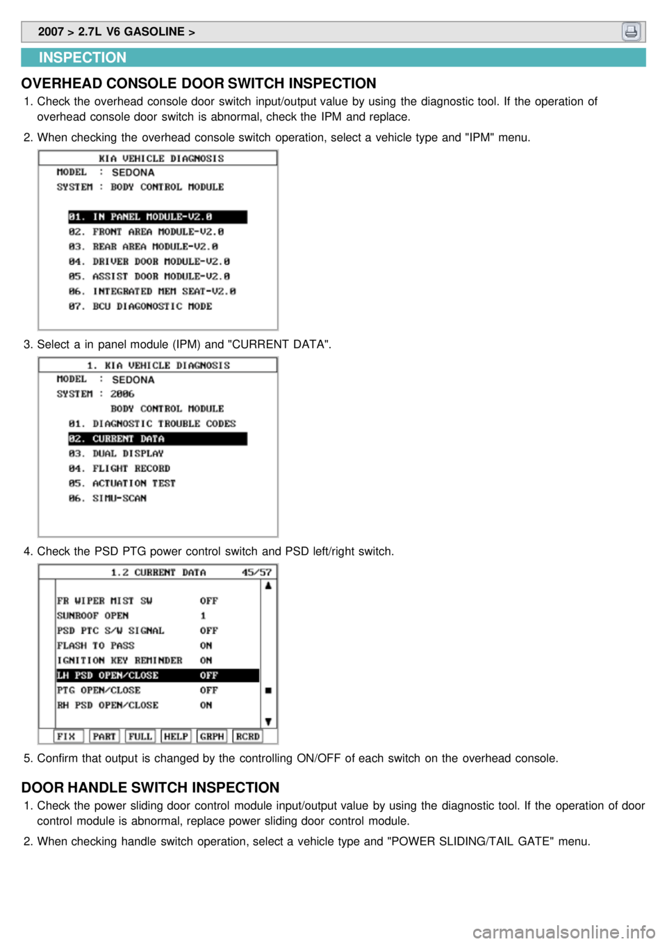
2. When checking the overhead console switch operation, select a vehicle type and "IPM" menu.
3.Select a in panel module (IPM) and "CURRENT DATA".
4.Check the PSD PTG power control switch and PSD left/right switch.
5.Confirm that output is changed by the controlling ON/OFF of each switch on the overhead console.
DOOR HANDLE SWITCH INSPECTION
1.Check the power sliding door control module input/output value by using the diagnostic tool. If the operation of door
control module is abnormal, replace power sliding door control module.
2. When checking handle switch operation, select a vehicle type and "POWER SLIDING/TAIL GATE" menu.
Page 1355 of 1575
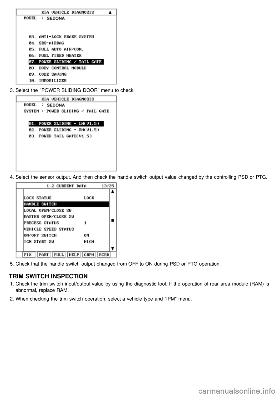
3.Select the "POWER SLIDING DOOR" menu to check.
4.Select the sensor output. And then check the handle switch output value changed by the controlling PSD or PTG.
5.Check that the handle switch output changed from OFF to ON during PSD or PTG operation.
TRIM SWITCH INSPECTION
1.Check the trim switch input/output value by using the diagnostic tool. If the operation of rear area module (RAM) is
abnormal, replace RAM.
2. When checking the trim switch operation, select a vehicle type and "IPM" menu.
Page 1390 of 1575
2007 > 2.7L V6 GASOLINE >
INSPECTION
OVERHEAD CONSOLE DOOR SWITCH INSPECTION
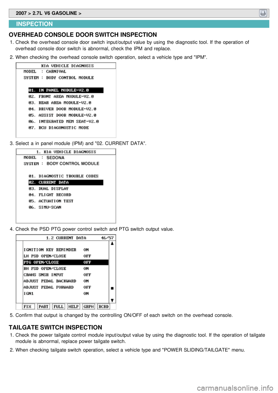
1. Check the overhead console door switch input/output value by using the diagnostic tool. If the operation of
overhead console door switch is abnormal, check the IPM and replace.
2. When checking the overhead console switch operation, select a vehicle type and "IPM".
3.Select a in panel module (IPM) and "02. CURRENT DATA".
4.Check the PSD PTG power control switch and PTG switch output value.
5.Confirm that output is changed by the controlling ON/OFF of each switch on the overhead console.
TAILGATE SWITCH INSPECTION
1.Check the power tailgate control module input/output value by using the diagnostic tool. If the operation of tailgate
module is abnormal, replace power tailgate switch.
2. When checking tailgate switch operation, select a vehicle type and "POWER SLIDING/TAILGATE" menu.
Page 1405 of 1575

2007 > 2.7L V6 GASOLINE >
DESCRIPTION
Windshield deicer system prevent windshield wiper from freezing in the winter season. It consists of deicer in the
lower part of windshield, switch and relay. FAM receives an input signal from the deicer switch of IPM through CAN
communication line and then controls relay. Operating condition is the same that of rear window defogger system.
With the engine running and the charging system operating, if the deicer switch is ON, then deicer output is ON for 20
minutes.
Page 1420 of 1575

2007 > 2.7L V6 GASOLINE >
INSPECTION
While operating the components, check whether the operations are normal as shown in the timing chart.
1. The defog function can be activated only when engine is running and ignition key is in RUN position.
If the defogger is switched ON, the defogger will stay ON for 20 minutes duration.
While Windshield Defog is on, the windshield defog button is illuminated
If the switch is pushed again while defog is already active, defog stops.
If the engine stops while defog is on, defog stops and it is not automatically turned on when the engine is started
again.
Rear defog works exactly in the same way as windshield defog using the Rear Defog Switch button as input.
2.Rear Defog Pause
When IPM receives tailgate flasher control CAN message transition to tailgate flash value, rear defog is inhibited for
30s.
The 20 min rear defog timer is frozen during this pause.
If the user turns on rear defog function while this pause is going on, rear defog is set to ON only at the end of the
pause.
This pause has no impact on Rear Defog Switch illumination.
When IPM receives tail gate open CAN message transition to OPEN value, this 30 s rear defog pause is also
started, it works the same way as described above.
Page 1469 of 1575

2007 > 2.7L V6 GASOLINE >
REPLACEMENT
1.Disconnect the negative ( - ) battery terminal.
2. Loose the mounting bolts (2EA).
3.Remove the head lamp assembly after disconnecting the lamp connectors.
Take care that holding clip (A) is not to be damaged.
4.Remove the head lamp rear cover and pulling up head lamp bulb fixing wire clip.
5.Replace the bulb.
6. Installation is the reverse of removal.
HEAD LAMP AIMING INSTRUCTIONS
Alternately turn the adjusting gear to adjust the head lamp aiming. If beam- setting equipment is not available, proceed
as follows :
1. Inflate the tires to the specified pressure and remove any loads from the vehicle except the driver, spare tire, and
tools.