FAM KIA CARNIVAL 2007 Workshop Manual
[x] Cancel search | Manufacturer: KIA, Model Year: 2007, Model line: CARNIVAL, Model: KIA CARNIVAL 2007Pages: 1575, PDF Size: 44.86 MB
Page 67 of 1575

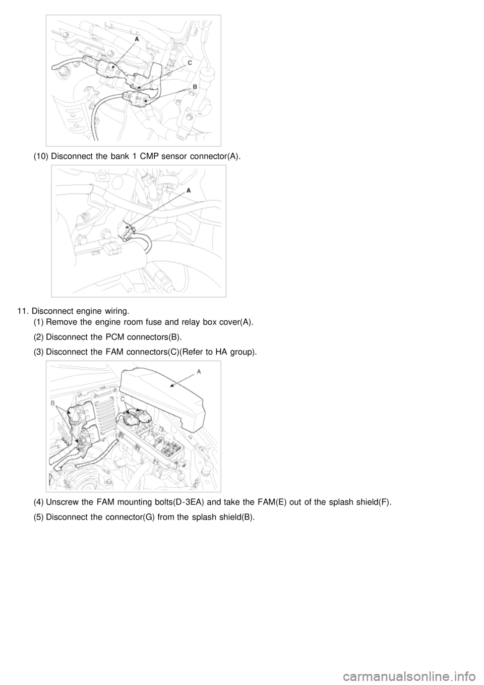
(10)Disconnect the bank 1 CMP sensor connector(A).
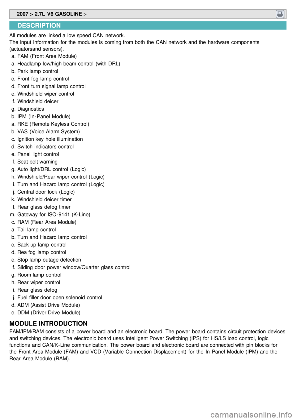
11.Disconnect engine wiring.
(1) Remove the engine room fuse and relay box cover(A).
(2) Disconnect the PCM connectors(B).
(3) Disconnect the FAM connectors(C)(Refer to HA group).
(4)Unscrew the FAM mounting bolts(D - 3EA) and take the FAM(E) out of the splash shield(F).
(5) Disconnect the connector(G) from the splash shield(B).
Page 1211 of 1575

2007 > 2.7L V6 GASOLINE >
DESCRIPTION
All modules are linked a low speed CAN network.
The input information for the modules is coming from both the CAN network and the hardware components
(actuatorsand sensors).
a. FAM (Front Area Module)
a. Headlamp low/high beam control (with DRL)
b. Park lamp control
c. Front fog lamp control
d. Front turn signal lamp control
e. Windshield wiper control
f. Windshield deicer
g. Diagnostics
b. IPM (In - Panel Module)
a. RKE (Remote Keyless Control)
b. VAS (Voice Alarm System)
c. Ignition key hole illumination
d. Switch indicators control
e. Panel light control
f. Seat belt warning
g. Auto light/DRL control (Logic)
h. Windshield/Rear wiper control (Logic)
i. Turn and Hazard lamp control (Logic)
j. Central door lock (Logic)
k. Windshield deicer timer
l. Rear glass defog timer
m. Gateway for ISO- 9141 (K- Line)
c. RAM (Rear Area Module)
a. Tail lamp control
b. Turn and Hazard lamp control
c. Back up lamp control
d. Rea fog lamp control
e. Stop lamp outage detection
f. Sliding door power window/Quarter glass control
g. Room lamp control
h. Rear wiper control
i. Rear glass defog
j. Fuel filler door open solenoid control
d. ADM (Assist Drive Module)
e. DDM (Driver Drive Module)
MODULE INTRODUCTION
FAM/IPM/RAM consists of a power board and an electronic board. The power board contains circuit protection devices
and switching devices. The electronic board uses Intelligent Power Switching (IPS) for HS/LS load control, logic
functions and CAN/K- Line communication. The power board and electronic board are connected with pin blocks for
the Front Area Module (FAM) and VCD (Variable Connection Displacement) for the In- Panel Module (IPM) and the
Rear Area Module (RAM).
Page 1215 of 1575

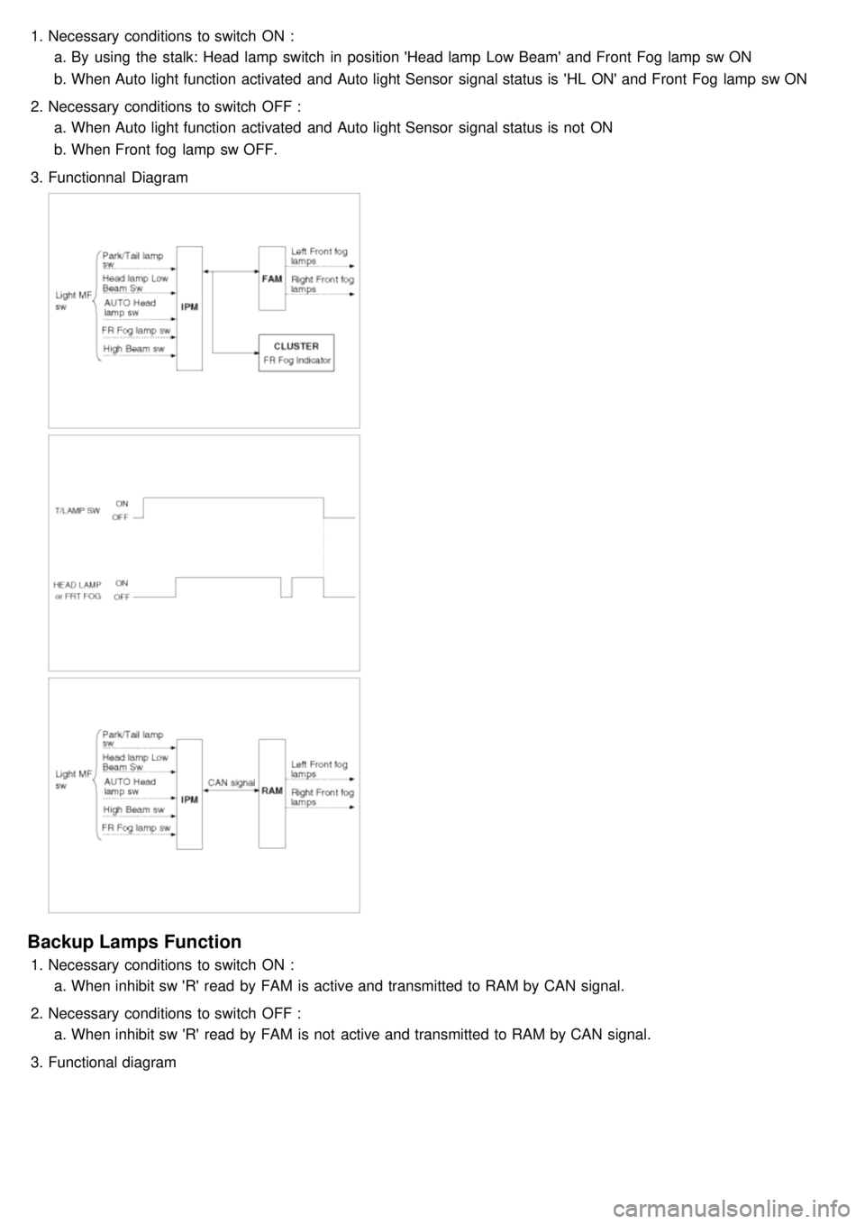
1.Necessary conditions to switch ON :
a. By using the stalk: Head lamp switch in position 'Head lamp Low Beam' and Front Fog lamp sw ON
b. When Auto light function activated and Auto light Sensor signal status is 'HL ON' and Front Fog lamp sw ON
2. Necessary conditions to switch OFF :
a. When Auto light function activated and Auto light Sensor signal status is not ON
b. When Front fog lamp sw OFF.
3. Functionnal Diagram
Backup Lamps Function
1.Necessary conditions to switch ON :
a. When inhibit sw 'R' read by FAM is active and transmitted to RAM by CAN signal.
2. Necessary conditions to switch OFF :
a. When inhibit sw 'R' read by FAM is not active and transmitted to RAM by CAN signal.
3. Functional diagram
Page 1227 of 1575

Easy Access
1.Description
The easy access function permits automatic rearward movement of the driver seat when the key is removed from
the cylinder. Automatic forward movement of the driver seat will take place when the key is inserted into the
cylinder. This function will be enabled on IMS equipped vehicles when the AUTO button is pressed.
Inhibit Switch should be in P- Position for the Easy Access operation.
2. Functional Diagram
Driver Information
Cluster Indicators
1.The instument cluster indicators listed below are controlled by the In- Panel Module (IPM), Front Area Module
(FAM), or Rear Area Module (RAM) as applicable.
These indicators are:
a. Gearbox status
b. Oil pressure
c. Sediment fuel filter
d. Vacuum
e. Brake fluid
f. Washer fluid
g. Seat belt
h. Park brake
i. Charging voltage
j. Turn indicators
k. High beam
l. Front fog
m. Doors open
n. Tailgate open
o. Stop lamp failure front and rear
2. Functional Diagram
Page 1228 of 1575

Gearbox Status
The status of the gearbox is sent on the CAN network when the CAN network is available.
Oil Pressure Switch Status
The status of the oil pressure switch is sent on the CAN network when the CAN network is available.
Fuel Filter Status
The FAM receives on digital input the status of the fuel filter (Fuel Filter Input) and sends it (Fuel filter switch) on the
CAN network.
Washer Fluid Sensor Status
The FAM receives on digital input the status of the washer fluid sensor and sends it on the CAN network.
If Washer Fluid Low Input is LOW for more than 10 sec, FAM sends the warning message.
Seat Belt Warning Status
The IPM receives on digital input the status of the seat belt switch and sends the seat belt warning on the CAN
network.
If the Ignition switch status is in RUN or START when the Seat Belt Sw Input is FASTENED, the seat belt warning
indicator is blinking for 6 seconds.
When Seat Belt switch Input is NOT FASTENED, the seat belt warning indicator is blinking for 6 seconds.
If the Seat Belt switch Input is FASTENED during the 6 seconds, the seat belt warning indicator is blinking till the end
of the 6 seconds.
In North America:
the seat belt warning indicator is blinking when Ignition switch is on the status RUN or START and Seat Belt Sw Input
is NOT FASTENED.
Parking Brake Indicator
The indicator manages 3 functions: brake fluid sensor, parking brake warning and vacuum switch.
The vacuum function is available for diesel engine only
The FAM receives on digital input the status of the vacuum switch and the ABS EBD warning and sends them on the
CAN network.
The status of the vacuum switch and the ABS EBD warning are sent on the CAN network when the CAN network is
available.
The FAM receives on digital input the status of the brake fluid sensor and sends it on the CAN network.
The status of the brake fluid sensor is sent on the CAN network when the CAN network is available.
The IPM receives on digital input the status of the parking brake switch and by CAN network the status of the vacuum
switch, the status of the ABS EBD warning, the status of the brake fluid sensor and the speed of the vehicle.
Page 1236 of 1575

Battery Removal
a.If the battery is removed with the system in the ARM state, the system will be placed into the ARM state upon
battery reconnect.
b. The ALARM state will be re- activated if the battery is disconnected, then reconnected, with the system in an
ALARM state.
c. If the battery is disconnected and reconnected with the system in AFTER ALARM state, the alarm will be re-
activated.
d. The system will enter DISARM mode if the battery is disconnected during the ALARM WAIT state.
Panic
a.If RKE PANIC signal is received, Siren output and hazard lamp operate for 27 seconds and the system return to
the previous state as soon as the PANIC function finishes.
b. The PANIC function will be stopped if any RKE signal is received during PANIC activation..
c. If Key reminder switch is ON during PANIC function is operating, PANIC is stopped immediately.
d. If the system goes to ALARM mode during PANIC function is operating, PANIC is stopped immediately and then
ALARM function should be activated.
e. During ALARM state;
If RKE PANIC signal is received, ALARM mode is maintained and PANIC function should be ignored. ALARM has
higher priority than PANIC function.
f. During AFTER_ALARM state;
If RKE PANIC signal is received, AFTR_ALARM mode is maintained and PANIC function should be activated.
Safe & Rescue Mode
The goal of those modes is to be able to cope with failures that may happen on some of the most critical
functionalities (for the driver security) of the system.
Safe Mode
The safe mode is entered in case of system problems such as:
a. Incoherent inputs on monitored signals. In this case, safe mode is the debouncing time before the inputs are
considered INVALID. Note that today, we have no way to detect if the rain/light sensor is in working operation or
not. It means that a driver action will be required in case of failure of this sensor;
b. Loss of the CAN frame containing the monitored signal:
c. Loss of the CAN network: CAN goes to BUS OFF state, safe mode is the time necessary for detecting the BUS
OFF state.
In all cases, the action in safe mode is to maintain the previous state of the system (for lighting and wiping). The list of
monitored signals is the same as in rescue mode
Exiting Safe Mode
The software safe mode is exited and the module goes back to the normal mode when: a. On IPM, hardware inputs return to a coherent state;
b. The lost CAN signal comes back while timeout has not elapsed;
c. The CAN network returns to a normal state without reaching BUS OFF state.
Software safe mode is also exited when the software rescue mode is entered (problem does not disappear).
Hardware safe mode is exited and the module goes back to normal mode if the internal problem disappears (watchdog
is properly triggered again). If the problem stays, hardware safe mode is exited to enter hardware rescue mode.
Rescue Modes
The rescue mode consists in activating some safety functions when IGN2 = ON: a. Switch on the low beams (FAM), park lamps (FAM), tail lamps (RAM) and cluster backlighting (IPM);
b. Unlock of all the doors when the rescue mode is entered with IGN2 = ON
c. Front wipers do not need to be turned on by software in rescue mode because wipers can be turned on by
manually setting the MF switch to low speed. The FAM software must keep the same state as before entering the
rescue mode.
d. When IGN2 = OFF, low beams, park/tail lamps and cluster backlighting are turned off.
Entering Rescue Modes
Page 1237 of 1575

Rescue mode is entered when some important CAN signal or hardware input are not available. Rescue mode is
entered when one of the following conditions is true:
IPMa. Timeout on CAN signal InhibitSwSts, to detect loss of CAN connection with FAM.
b. Timeout on CAN signal StopLpErrorSts, to detect loss of CAN connection with RAM.
c. MF Light Switch information is invalid: when the signals coming from MF Light Switch are not coherent for more
than 2 s, CAN signal ParkTailHeadLpCtrl is sent with INVALID value and rescue mode is entered.
d. Front Wiper MF Switch information is invalid: when the signals coming from Front Wiper MF Switch are not
coherent for more than 2 s, CAN signal FWiperCtrl is sent with INVALID value and rescue mode is entered.
e. CAN is in Bus Off state
RAM a. Timeout on CAN signal InhibitSwSts, to detect loss of CAN connection with FAM.
b. Timeout on CAN signal ParkTailHeadLpCtrl or FWiperCtrl, to detect loss of CAN connection with IPM.
c. ParkTailHeadLpCtrl = INVALID or unknown value
d. FWiperCtrl = INVALID or unknown value
e. CAN is in Bus Off state
FAM a. Timeout on CAN signal StopLpErrorSts, to detect loss of CAN connection with RAM
b. Timeout on CAN signal ParkTailHeadLpCtrl or FWiperCtrl, to detect loss of CAN connection with IPM
c. ParkTailHeadLpCtrl = INVALID or unknown value
d. FWiperCtrl = INVALID or unknown value
e. CAN is in Bus Off state
For all CAN signals, timeout duration is 2.5 times signal periodicity.
Page 1240 of 1575

2.The IPM communicates with the diagnostic tester directly. But other units operate self diagnostic, input/output
monitoring and actuator operation via the IPM using the CAN communication.
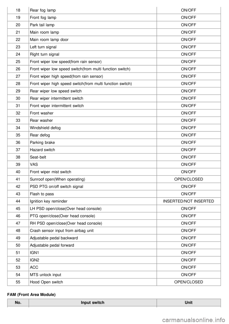
INPUT MONITORING
IPM (In- Panel Module)
No. Input switch Unit
1 IPM Node Availability PRESENT/NOT PRESENT
2 FAM Node Availability PRESENT/NOT PRESENT
3 RAM Node Availability PRESENT/NOT PRESENT
4 DDM Node Availability PRESENT/NOT PRESENT
5 ADM Node Availability PRESENT/NOT PRESENT
6 IMS Node Availability PRESENT/NOT PRESENT
7 CLU Node Availability PRESENT/NOT PRESENT
8 IPM Node Failure FAILURE/ O.K
9 FAM Node Failurey FAILURE/ O.K
10 RAM Node Failure FAILURE/ O.K
11 DDM Node Failure FAILURE/ O.K
12 ADM Node Failure FAILURE/ O.K
13 IMS Node Failure FAILURE/ O.K
14 CLU Node Failure FAILURE/ O.K
15 Auto Head lamp ON/OFF
16 Headlamp low beam ON/OFF
17 High beam ON/OFF
Page 1241 of 1575

18Rear fog lamp ON/OFF
19 Front fog lamp ON/OFF
20 Park tail lamp ON/OFF
21 Main room lamp ON/OFF
22 Main room lamp door ON/OFF
23 Left turn signal ON/OFF
24 Right turn signal ON/OFF
25 Front wiper low speed(from rain sensor) ON/OFF
26 Front wiper low speed switch(from multi function switch) ON/OFF
27 Front wiper high speed(from rain sensor) ON/OFF
28 Front wiper high speed switch(from multi function switch) ON/OFF
29 Rear wiper low speed switch ON/OFF
30 Rear wiper intermittent switch ON/OFF
31 Front wiper intermittent switch ON/OFF
32 Front washer ON/OFF
33 Rear washer ON/OFF
34 Windshield defog ON/OFF
35 Rear defog ON/OFF
36 Parking brake ON/OFF
37 Hazard switch ON/OFF
38 Seat- belt ON/OFF
39 VAS ON/OFF
40 Front wiper mist switch ON/OFF
41 Sunroof open(When operating) OPEN/CLOSED
42 PSD PTG on/off switch signal ON/OFF
43 Flash to pass ON/OFF
44 Ignition key reminder INSERTED/NOT INSERTED
45 LH PSD open/close(Over head console) ON/OFF
46 PTG open/close(Over head console) ON/OFF
47 RH PSD open/close(Over head console) ON/OFF
48 Crash sensor input from airbag unit ON/OFF
49 Adjustable pedal backward ON/OFF
50 Adjustable pedal forward ON/OFF
51 IGN1 ON/OFF
52 IGN2 ON/OFF
53 ACC ON/OFF
54 MTS unlock input ON/OFF
55 Hood Open switch OPEN/CLOSED
FAM (Front Area Module) No. Input switch Unit
Page 1244 of 1575

6IGN2 Switch ON/OFF
7 Front Right Window Up Switch ON/OFF
8 Front Right Window Down Switch ON/OFF
IMS Module No. Input switch Unit
1 IGN2 Switch ON/OFF
2 Slide front manual switch ON/OFF
3 Slide rear manual switch ON/OFF
4 Slide front limit switch ON/OFF
5 Slide rear limit switch ON/OFF
6 Recline front manual switch ON/OFF
7 Recline rear manual switch ON/OFF
8 "P" position switch ON/OFF
Self-diagnosis
IPM DTC List
No. DTC Code DTC Passiblecause
1 B1102 BATTERY VOLTAGE LOW Vbat < 9V
2 B1588 FR WIPER/WASHER MF
SW
MF switch status is not coherent for more than 2s
3 B1589 RR WIPER/WASHER MF
SW
4 B1590 LIGHT MF SW ERROR
MF switch status is not coherent for more than 2s
5 B1591 TURN SIGNAL MF SW
ERROR
6 B1602 CAN BUS PHYSICAL BUS
FAILURE Physical error indicated by network management
7 B1605 DDM COMM. LOST& BUS
FAILURE DDM is missing in system configuration information reported from
network management.
8 B1606 ADM COMM. LOST& BUS
FAILURE ADM is missing in system configuration information reported from
network management.
9 B1607 IMS COMM. LOST& BUS
FAILURE IMS is missing in system configuration information reported from
network management.
10 B1611 FAM COMM. LOST& BUS
FAILURE FAM is missing in system configuration information reported from
network management.
11 B1612 RAM COMM. LOST& BUS
FAILURE RAM is missing in system configuration information reported from
network management.
12 B1613 CLU COMM. LOST& BUS
FAILURE CLU is missing in system configuration information reported from
network management.
13 B1624 EEPROM FAILURE Failed attempt to read or write EEPROM
14 B1627 EEPROM CORRUPTION Data in EEPROM is not coherent
15 B1628 MODULE CONF.
CONFLICT Hardware and software configuration are not coherent