monitor KIA CARNIVAL 2007 Workshop Manual
[x] Cancel search | Manufacturer: KIA, Model Year: 2007, Model line: CARNIVAL, Model: KIA CARNIVAL 2007Pages: 1575, PDF Size: 44.86 MB
Page 277 of 1575

2007 > 2.7L V6 GASOLINE >
INSPECTION
FUNCTION AND OPERATION PRICIPLE
Accelerator Position Sensor (APS) is installed on the accelerator pedal module and detects the rotation angle of the
accelerator pedal. The APS is one of the most important sensors in engine control system, so it consists of the two
sensors which adapt individual sensor power and ground line. The second sensor monitors the first sensor and its
output voltage is half of the first one. If the ratio of the sensor 1 and 2 is out of the range (approximately 1/2), the
diagnostic system judges that a malfunction has occurred.
SPECIFICATION
Pedal Position Output Voltage (V) [Vref = 5.0V]
APS1 APS2
C.T 0.7 ~ 0.8V 0.29 ~ 0.46V
W.O.T 3.85 ~ 4.35V 1.93 ~ 2.18V
Item Sensor Resistance
APS1 0.7 ~ 1.3kΩ at 20°C (68°F)
APS2 1.4 ~ 2.6kΩ at 20°C (68°F)
CIRCUIT DIAGRAM
Page 303 of 1575

2007 > 2.7L V6 GASOLINE >
INSTALLATION
If the OCVs are installed incorrectly, the vehicle may be damaged.
So when installing them, ensure the OCV and harness connector colors match(Components and harness side).
[Bank and its color] Bank Component side Harness side
Bank 1 (RH) GreyGrey
Bank 2 (LH) BlackBlack
INSPECTION
FUNCTION AND OPERATION PRICIPLE
The Continuously Variable Valve Timing (CVVT) system controls the amount of valve overlap by varying the amount of
oil flow into an assembly mounted on each intake camshaft through PCM control of an oil control valve. This system
uses two oil control valves, one on each bank. An Oil Temperature Sensor (OTS) is used to allow PCM monitoring of
engine oil temperature. As oil is directed into the chambers of the CVVT assembly, the cam phase is changed to suit
various performance and emissions requirements.. 1. When camshaft rotates engine rotation- wise: Intake- Advance / Exhaust- Retard
2. When camshaft rotates counter engine rotation- wise: Intake- Retard / Exhaust- Advance
SPECIFICATION
Item Specification
Coil Resistance (Ω) 6.7 ~ 7.7Ω at 20°C (68°F)
CIRCUIT DIAGRAM
Page 729 of 1575

3.The two coolant temperature sensors are installed to the heater inner. The sensor valves determine heater
operation.
4. One of the temperature sensors functions to prevent the heater from overheating.
If the sensor temperature valve exceeds 125°C, the fuel will be cut and the heater will be deactivated by the
determination of the overheating of the heater.
The other temperature sensor determines the operation mode of the fuel fired heater.The temperature of this
sensor enables to activate the heater at full load(5kw) or half load(2.5kw).
• The coolant temperature shown on the above Figure is the value of the inner sensor and the actual coolant
temperature is higher about 5°C ~7°C than the above value.
OPERATION
Switch on/ Operation start
The fuel fired heater is operated when the coolant temperature is below 68°C and the ambient temperature is below
2°C after starting the engine.
At this time, the glow plug and combustion air fan are operated first and after 30 seconds, the dosing pump is
operated with stopping the combustion fan for 3 seconds.
After that, the operation of the fan increases continuously until it approaches to full load within 56 seconds. If fuel
supply reaches to full load the glow plug does not operate and the operation of the fan reaches to full load.
After that the glow plug monitors ignition condition as a flame sensor for 45 seconds.
The above operation procedure is done automatically and in case the ignition fails, the above operation will be done
again automatically.
If the condition of ignition failure sustains continuously, fuel supply and fan operation will be stopped and error codes
will be stored to find cause of failure.
Generally, the cause of ignition failure during combustion is caused by the automatic re- operation of the above
procedure.
Operation for heating
The fuel fired heater operates at full load when the coolant temperature is below 68°C and the ambient temperature is
below 2°C after starting the engine.
It operates at half load when the coolant temperature is 74°C and it operates at idle mode when the coolant
temperature is 78°C.
The fuel fired heater during the transformation process does a cleaning function from the half mode to the idle mode.
At idle mode, all components do not work.
The fuel fired heater operating at idle mode turns into the half load when the coolant temperature is 74°C. At this time,
if the coolant temperature drops again below 68°C, the heater operates with full load and turns into the idle mode if
the temperature is 78°C.
This serial operating process is performed automatically.
Key switch off / Operation stop
The fuel fired heater ECU stops the operation of the fuel pump and cuts fuel supply when shutting off the engine
during the heater operation.
The heater conducts cleaning operation at this time.
This is a process of burning the fuel completely supplied in the heater inner.
In this process, the glow plug and combustion air fan are operated.
Page 795 of 1575

2007 > 2.7L V6 GASOLINE >
General
The supplemental restraint system (SRS) is designed to supplement the seat belt to help reduce the risk or severity of
injury to the driver and passenger by activating and deploying the driver, passenger, side airbag and belt pretensioner
in certain frontal or side collisions.
The SRS (Airbag) consists of : a driver side airbag module located in the center of the steering wheel, which contains
the folded cushion and an inflator unit ; a passenger side airbag module located in the passenger side crash pad
contains the folded cushion assembled with inflator unit ; side airbag modules located in the driver and passenger seat
contain the folded cushion and an inflator unit ; curtain airbag modules located inside of the headliner which contains
folded cushions and inflator units. The impact sensing function of the SRSCM is carried out by electronic
accelerometer that continuously measure the vehicle's acceleration and delivers a corresponding signal through
amplifying and filtering circuitry to the microprocessor.
SRSCM (SRS Control Module)
SRSCM will detect front impact with front impact sensor, and side impact with side impact sensor, and determine
airbag module deployment.
1. DC/DC converter: DC/DC converter in power supply unit includes up/down transformer converter, and provide
ignition voltage for 2 front airbag ignition circuits and the internal operation voltage of the SRSCM. If the internal
operation voltage is below critical value setting, it will perform resetting.
2. Safety sensor: Safety sensor is located in airbag ignition circuit. Safety sensor will operate airbag circuit at any
deployment condition and release airbag circuit safely at normal driving condition. Safety sensor is a double contact
electro - mechanical switch that will close detecting deceleration above certain criteria.
3. Back up power supply: SRSCM has separate back up power supply, that will supply deployment energy instantly in
low voltage condition or upon power failure by front crash.
4. Self diagnosis: SRSCM will constantly monitor current SRS operation status and detect system failure while vehicle
power supply is on, system failure may be checked with trouble codes using scan tool. (Hi- Scan)
5. Airbag warning lamp on: Upon detecting error, the module will transmit signal to SRSCM indicator lamp located at
cluster. MIL lamp will indicate driver SRS error. Upon ignition key on, SRS lamp will turn on for about six seconds.
6. Trouble code registration: Upon error occurrence in system, SRSCM will store DTC corresponding to the error.
DTC can be cleared only by Hi - Scan. However, if an internal fault code is logged or if a crash is recorded the fault
clearing should not happen.
7. Self diagnostic connector: Data stored in SRSCM memory will be output to Hi - Scan or other external output
devices through connector located below driver side crash pad.
8. Once airbag is deployed, SRSCM should not be used again but replaced.
9. SRSCM will determine whether passenger put on seat belt by the signal from built- in switch in seat belt buckle, and
deploy front seat airbag at each set crash speed.
10. Side airbag deployment will be determined by SRSCM that will detect satellite sensor impact signal upon side
crash, irrespective to seat belt condition.
Page 928 of 1575

2007 > 2.7L V6 GASOLINE >
DESCRIPTION
This specification applies to HCU(Hydraulic Control Unit) and ECU(Electronic Control Unit) of the HECU.(Hydraulic and
Electronic Control Unit)
This specification is for the wiring design and installation of ABS/TCS/ESC ECU.
This unit has the functions as follows.
a. Input of signal from Pressure sensor, Steering angle sensor, Yaw & Lateral G sensor, the wheel speed sensors
attached to each wheel.
b. Control of braking force / traction force/ yaw moment.
c. Failsafe function.
d. Self diagnosis function.
e. Interface with the external diagnosis tester.
Installation position : engine compartment a. Brake tube length from Master cylinder port to HECU inlet port should be max. 1m
b. The position should not be close to the engine block and not lower than the wheel.
OPERATION
The ECU shall be put into operation by switching on the operating voltage (IGN).
On completion of the initialization phase, the ECU shall be ready for operation.
In the operating condition, the ECU shall be ready, within the specified limits (voltage and temperature), to process the
signals offered by the various sensors and switches in accordance with the control algorithm defined by the software
and to control the hydraulic and electrical actuators.
Wheel Sensor signal processing
The ECU shall receive wheel speed signal from the four active wheel sensors.
The wheel signals are converted to voltage signal by the signal conditioning circuit after receiving current signal from
active wheel sensors and given as input to the MCU.
Solenoid Valve Control
When one side of the valve coil is connected to the positive voltage that is provided through the valve relay and the
other side is connected to the ground by the semiconductor circuit, the solenoid valve goes into operation.
The electrical function of the coils are always monitored by the valve test pulse under normal operation conditions.
Voltage limits
a.Overvoltage
When overvoltage is detected(above 16.8 V), the ECU switches off the valve relay and shuts down the system.
When voltage is returned to operating range, the system goes back to the normal condition after the initialization
phase.
b. Undervoltage
In the event of undervoltage(below 9.3 V), ABS control shall be inhibited and the warning lamp shall be turned on.
When voltage is returned to operating range, the warning lamp is switched off and ECU returns to normal operating
mode.
Pump Motor Checking
The ECU performs a pump motor test at a speed of 15km/h once after IGN is switched on.
Diagnostic Interface
Failures detected by the ECU are encoded on the ECU, stored in a EEPROM and read out by diagnostic equipment
when the ignition switch is turned on.
The diagnosis interface can also be used for testing the ECU during production of the ECU and for actuating the HCU
(Air - bleeding line or Roll and Brake Test line).
Warning Lamp module
Page 1176 of 1575
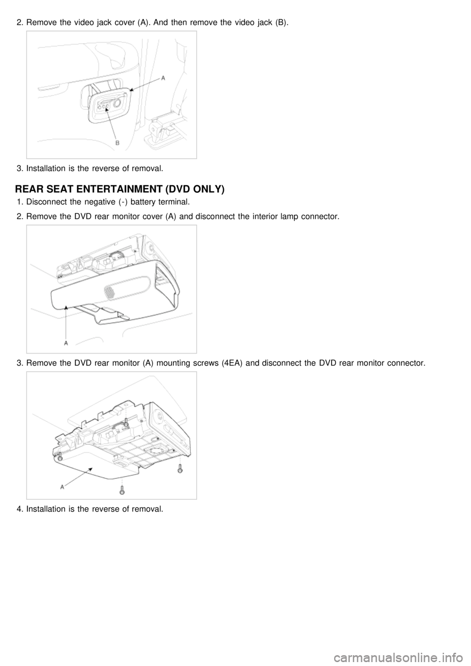
2.Remove the video jack cover (A). And then remove the video jack (B).
3.Installation is the reverse of removal.
REAR SEAT ENTERTAINMENT (DVD ONLY)
1.Disconnect the negative ( - ) battery terminal.
2. Remove the DVD rear monitor cover (A) and disconnect the interior lamp connector.
3.Remove the DVD rear monitor (A) mounting screws (4EA) and disconnect the DVD rear monitor connector.
4.Installation is the reverse of removal.
Page 1212 of 1575
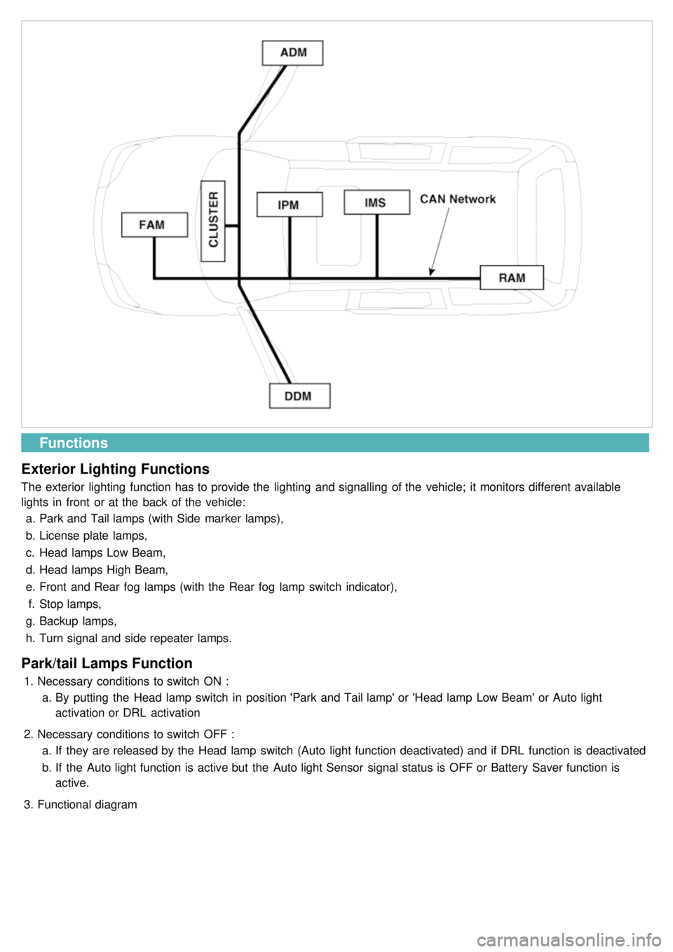
Functions
Exterior Lighting Functions
The exterior lighting function has to provide the lighting and signalling of the vehicle; it monitors different available
lights in front or at the back of the vehicle: a. Park and Tail lamps (with Side marker lamps),
b. License plate lamps,
c. Head lamps Low Beam,
d. Head lamps High Beam,
e. Front and Rear fog lamps (with the Rear fog lamp switch indicator),
f. Stop lamps,
g. Backup lamps,
h. Turn signal and side repeater lamps.
Park/tail Lamps Function
1.Necessary conditions to switch ON :
a. By putting the Head lamp switch in position 'Park and Tail lamp' or 'Head lamp Low Beam' or Auto light
activation or DRL activation
2. Necessary conditions to switch OFF :
a. If they are released by the Head lamp switch (Auto light function deactivated) and if DRL function is deactivated
b. If the Auto light function is active but the Auto light Sensor signal status is OFF or Battery Saver function is
active.
3. Functional diagram
Page 1221 of 1575

ONDon't care OFFONON
DOOR OPEN
ON during 20 min
then directly OFF ON during 20 min
OFF
CLOSE
OFFOFF
OPEN → CLOSE OFF OFF
CLOSE → OPEN ON during 20 min
then directly OFF ON during 20 min
Door Courtesy Lamps
Key Hole Illumination
1.
Working Conditions
The key cylinder is illuminated when the driver and / or the assist door are open.
2. Key hole extinguish conditions:
a. The key cylinder is turned off 10s after the driver and assist doors are closed.
b. The key cylinder is turned off immediately if the key is inserted in the hole and put to RUN or START position.
c. For vehicles equipped with BurglarAlarm, the key cylinder is turned off immediately when the system goes to
ARM WAIT mode during the 10s after the driver and assist doors are closed.
d. For vehicles not equipped with BurglarAlarm, the key cylinder is turned off immediately when RKE lock signal is
received from keyfob during the 10s after the driver and assist doors are closed (4).
3. Functional Diagram
Panel Lights, Switch Illumination
1.Working Conditions
The MF "high beam" and "flash to pass" switches do not influence the management of the Panel Lights and Trip
Computer illumination, Rear Blower illumination and Rear Monitor illumination.
2. Functional Diagram
Page 1231 of 1575

1.The aim of this function is to receive the key fob signal and decode it. There are 8 different data included in the
radio frequency frame sent by the RKE to the IPM module:
a. Central door lock
b. Central door unlock
c. Panic function
d. Driver door window close (long press on RKE lock button)
e. Driver door window open (long press on RKE unlock button)
f. Left sliding door open/close
g. Right sliding door open/close
h. Power tailgate open/close
2. Each vehicle can have at most 2 associated key fobs. The key fob is physically separated from the key itself
(separate device).
3. Input/Output Definition and Characteristics
Central Lock/unlock
1.Central locking/unlocking logic is controlled by IPM. Locking/Unlocking inputs are located in ADM, DDM
(Lock/Unlock switch, door knobs, door key cylinder) and in IPM (RKE receiver).
2. Locking/Unlocking actuators are located in ADM for passenger door, DDM for driver door and RAM for sliding doors
and tailgate.
There are 5 ways of operating central lock/unlock:
a. With Key RKE
b. With Door Lock/Unlock switches located on ADM/DDM
c. With Door Lock Monitoring switches located on the passenger/driver door
d. With Door/Tailgate Key Cylinder Lock/Unlock switches located on the tailgate or passenger/driver door.
3. Functional Diagram
Page 1232 of 1575

Key Reminder Unlock
1.Key reminder door unlock does not take into account the lock/unlock commands from RKE, key cylinder or door
lock switches. It only takes into account the state of the door lock monitoring switch, key reminder switch and door
open status in order to proceed with the unlock sequence or not.
2. Functional Diagram
Remote Keyless Entry Panic
1.Working Conditions
RKE panic function is only active when the key is out of key cylinder.
Once started, panic operation is not stopped when ignition key is inserted, ignition is ACC, RUN or START, or
door is opened or closed.
2. Functional Diagram