oil pressure KIA CARNIVAL 2007 Workshop Manual
[x] Cancel search | Manufacturer: KIA, Model Year: 2007, Model line: CARNIVAL, Model: KIA CARNIVAL 2007Pages: 1575, PDF Size: 44.86 MB
Page 9 of 1575
2007 > 2.7L V6 GASOLINE >
TROUBLESHOOTING
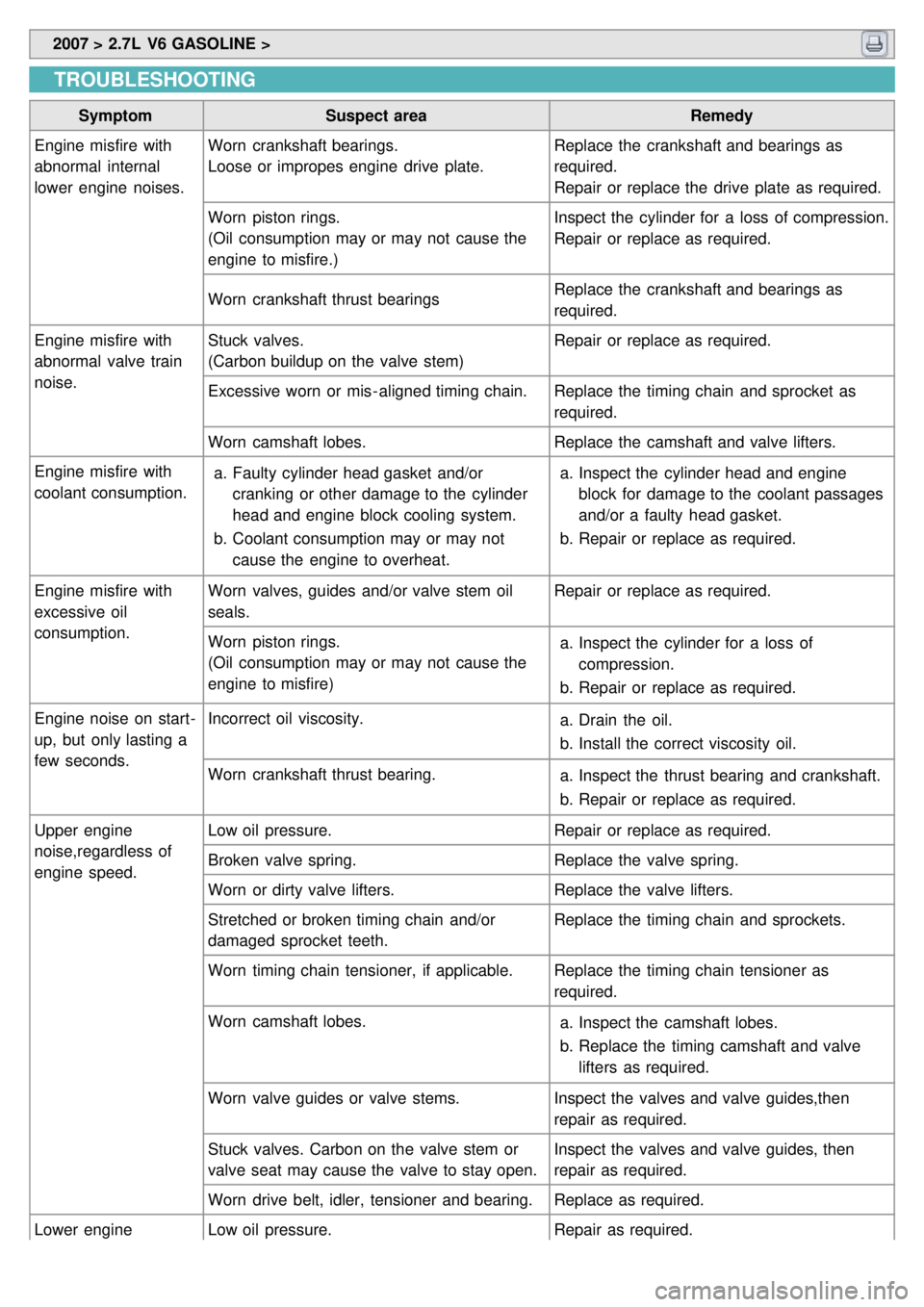
Symptom Suspect area Remedy
Engine misfire with
abnormal internal
lower engine noises. Worn crankshaft bearings.
Loose or impropes engine drive plate.
Replace the crankshaft and bearings as
required.
Repair or replace the drive plate as required.
Worn piston rings.
(Oil consumption may or may not cause the
engine to misfire.) Inspect the cylinder for a loss of compression.
Repair or replace as required.
Worn crankshaft thrust bearings Replace the crankshaft and bearings as
required.
Engine misfire with
abnormal valve train
noise. Stuck valves.
(Carbon buildup on the valve stem)
Repair or replace as required.
Excessive worn or mis - aligned timing chain. Replace the timing chain and sprocket as
required.
Worn camshaft lobes. Replace the camshaft and valve lifters.
Engine misfire with
coolant consumption. a.
Faulty cylinder head gasket and/or
cranking or other damage to the cylinder
head and engine block cooling system.
b. Coolant consumption may or may not
cause the engine to overheat. a.
Inspect the cylinder head and engine
block for damage to the coolant passages
and/or a faulty head gasket.
b. Repair or replace as required.
Engine misfire with
excessive oil
consumption. Worn valves, guides and/or valve stem oil
seals.
Repair or replace as required.
Worn piston rings.
(Oil consumption may or may not cause the
engine to misfire) a.
Inspect the cylinder for a loss of
compression.
b. Repair or replace as required.
Engine noise on start -
up, but only lasting a
few seconds. Incorrect oil viscosity.
a.Drain the oil.
b. Install the correct viscosity oil.
Worn crankshaft thrust bearing. a.Inspect the thrust bearing and crankshaft.
b. Repair or replace as required.
Upper engine
noise,regardless of
engine speed. Low oil pressure.
Repair or replace as required.
Broken valve spring. Replace the valve spring.
Worn or dirty valve lifters. Replace the valve lifters.
Stretched or broken timing chain and/or
damaged sprocket teeth. Replace the timing chain and sprockets.
Worn timing chain tensioner, if applicable. Replace the timing chain tensioner as
required.
Worn camshaft lobes. a.Inspect the camshaft lobes.
b. Replace the timing camshaft and valve
lifters as required.
Worn valve guides or valve stems. Inspect the valves and valve guides,then
repair as required.
Stuck valves. Carbon on the valve stem or
valve seat may cause the valve to stay open. Inspect the valves and valve guides, then
repair as required.
Worn drive belt, idler, tensioner and bearing. Replace as required.
Lower engine
noise,regardless of Low oil pressure.
Repair as required.
Page 10 of 1575
noise,regardless of
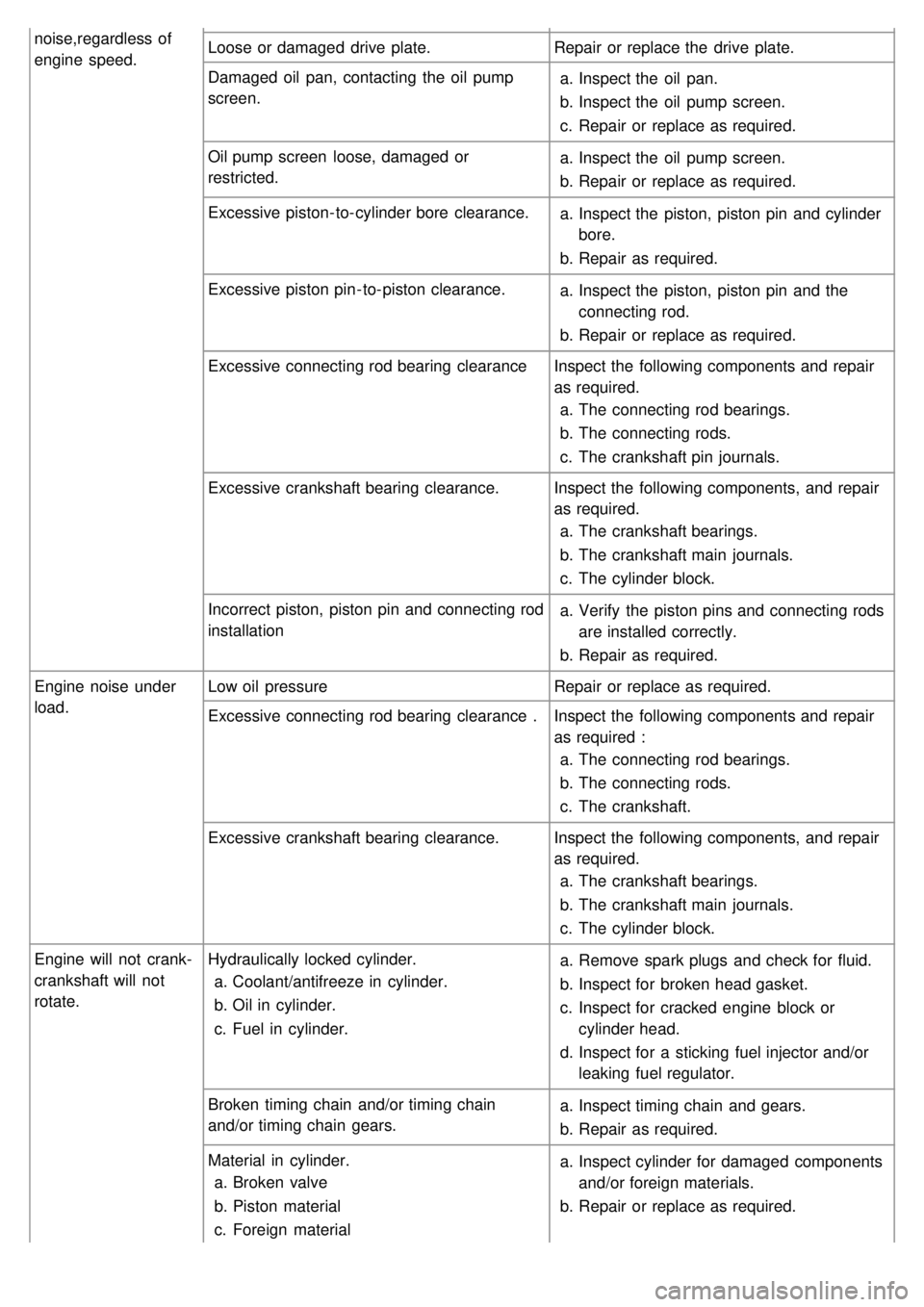
engine speed.Loose or damaged drive plate.
Repair or replace the drive plate.
Damaged oil pan, contacting the oil pump
screen. a.
Inspect the oil pan.
b. Inspect the oil pump screen.
c. Repair or replace as required.
Oil pump screen loose, damaged or
restricted. a.
Inspect the oil pump screen.
b. Repair or replace as required.
Excessive piston- to- cylinder bore clearance. a.Inspect the piston, piston pin and cylinder
bore.
b. Repair as required.
Excessive piston pin- to- piston clearance. a.Inspect the piston, piston pin and the
connecting rod.
b. Repair or replace as required.
Excessive connecting rod bearing clearance Inspect the following components and repair
as required.
a. The connecting rod bearings.
b. The connecting rods.
c. The crankshaft pin journals.
Excessive crankshaft bearing clearance. Inspect the following components, and repair
as required.
a. The crankshaft bearings.
b. The crankshaft main journals.
c. The cylinder block.
Incorrect piston, piston pin and connecting rod
installation a.
Verify the piston pins and connecting rods
are installed correctly.
b. Repair as required.
Engine noise under
load. Low oil pressure
Repair or replace as required.
Excessive connecting rod bearing clearance . Inspect the following components and repair
as required :
a. The connecting rod bearings.
b. The connecting rods.
c. The crankshaft.
Excessive crankshaft bearing clearance. Inspect the following components, and repair
as required.
a. The crankshaft bearings.
b. The crankshaft main journals.
c. The cylinder block.
Engine will not crank-
crankshaft will not
rotate. Hydraulically locked cylinder.
a. Coolant/antifreeze in cylinder.
b. Oil in cylinder.
c. Fuel in cylinder. a.
Remove spark plugs and check for fluid.
b. Inspect for broken head gasket.
c. Inspect for cracked engine block or
cylinder head.
d. Inspect for a sticking fuel injector and/or
leaking fuel regulator.
Broken timing chain and/or timing chain
and/or timing chain gears. a.
Inspect timing chain and gears.
b. Repair as required.
Material in cylinder. a. Broken valve
b. Piston material
c. Foreign material a.
Inspect cylinder for damaged components
and/or foreign materials.
b. Repair or replace as required.
Page 12 of 1575
2007 > 2.7L V6 GASOLINE >
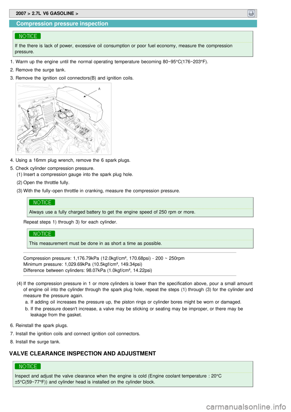
Compression pressure inspection
If the there is lack of power, excessive oil consumption or poor fuel economy, measure the compression
pressure.
1. Warm up the engine until the normal operating temperature becoming 80~95°C(176~203°F).
2. Remove the surge tank.
3. Remove the ignition coil connectors(B) and ignition coils.
4.Using a 16mm plug wrench, remove the 6 spark plugs.
5. Check cylinder compression pressure.
(1) Insert a compression gauge into the spark plug hole.
(2) Open the throttle fully.
(3) With the fully - open throttle in cranking, measure the compression pressure.
Always use a fully charged battery to get the engine speed of 250 rpm or more.
Repeat steps 1) through 3) for each cylinder.
This measurement must be done in as short a time as possible.
Compression pressure: 1,176.79kPa (12.0kgf/cm², 170.68psi) - 200 ~ 250rpm
Minimum pressure: 1,029.69kPa (10.5kgf/cm², 149.34psi)
Difference between cylinders: 98.07kPa (1.0kgf/cm², 14.22psi)
(4) If the compression pressure in 1 or more cylinders is lower than the specification above, pour a small amount
of engine oil into the cylinder through the spark plug hole, repeat the steps (1) through (3) for the cylinder and
measure the pressure again.
a. If adding oil increases the pressure up, the piston rings or cylinder bores might be worn or damaged.
b. If the pressure doesn't increase, a valve may be sticking or seating may be improper, or there may be
leakage from the gasket.
6. Reinstall the spark plugs.
7. Install the ignition coils and connect ignition coil connectors.
8. Install the surge tank.
VALVE CLEARANCE INSPECTION AND ADJUSTMENT
Inspect and adjust the valve clearance when the engine is cold (Engine coolant temperature : 20°C
±5°C(59~77°F)) and cylinder head is installed on the cylinder block.
Page 18 of 1575
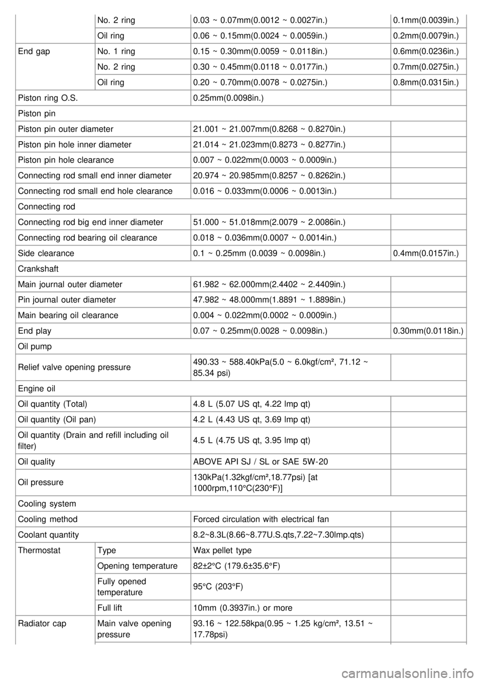
No. 2 ring0.03 ~ 0.07mm(0.0012 ~ 0.0027in.) 0.1mm(0.0039in.)
Oil ring 0.06 ~ 0.15mm(0.0024 ~ 0.0059in.) 0.2mm(0.0079in.)
End gap No. 1 ring 0.15 ~ 0.30mm(0.0059 ~ 0.0118in.) 0.6mm(0.0236in.)
No. 2 ring 0.30 ~ 0.45mm(0.0118 ~ 0.0177in.) 0.7mm(0.0275in.)
Oil ring 0.20 ~ 0.70mm(0.0078 ~ 0.0275in.) 0.8mm(0.0315in.)
Piston ring O.S. 0.25mm(0.0098in.)
Piston pin
Piston pin outer diameter 21.001 ~ 21.007mm(0.8268 ~ 0.8270in.)
Piston pin hole inner diameter 21.014 ~ 21.023mm(0.8273 ~ 0.8277in.)
Piston pin hole clearance 0.007 ~ 0.022mm(0.0003 ~ 0.0009in.)
Connecting rod small end inner diameter 20.974 ~ 20.985mm(0.8257 ~ 0.8262in.)
Connecting rod small end hole clearance 0.016 ~ 0.033mm(0.0006 ~ 0.0013in.)
Connecting rod
Connecting rod big end inner diameter 51.000 ~ 51.018mm(2.0079 ~ 2.0086in.)
Connecting rod bearing oil clearance 0.018 ~ 0.036mm(0.0007 ~ 0.0014in.)
Side clearance 0.1 ~ 0.25mm (0.0039 ~ 0.0098in.) 0.4mm(0.0157in.)
Crankshaft
Main journal outer diameter 61.982 ~ 62.000mm(2.4402 ~ 2.4409in.)
Pin journal outer diameter 47.982 ~ 48.000mm(1.8891 ~ 1.8898in.)
Main bearing oil clearance 0.004 ~ 0.022mm(0.0002 ~ 0.0009in.)
End play 0.07 ~ 0.25mm(0.0028 ~ 0.0098in.) 0.30mm(0.0118in.)
Oil pump
Relief valve opening pressure 490.33 ~ 588.40kPa(5.0 ~ 6.0kgf/cm², 71.12 ~
85.34 psi)
Engine oil
Oil quantity (Total) 4.8 L (5.07 US qt, 4.22 lmp qt)
Oil quantity (Oil pan) 4.2 L (4.43 US qt, 3.69 lmp qt)
Oil quantity (Drain and refill including oil
filter) 4.5 L (4.75 US qt, 3.95 lmp qt)
Oil quality ABOVE API SJ / SL or SAE 5W- 20
Oil pressure 130kPa(1.32kgf/cm²,18.77psi) [at
1000rpm,110°C(230°F)]
Cooling system
Cooling method Forced circulation with electrical fan
Coolant quantity 8.2~8.3L(8.66~8.77U.S.qts,7.22~7.30lmp.qts)
Thermostat Type Wax pellet type
Opening temperature 82±2°C (179.6±35.6°F)
Fully opened
temperature 95°C (203°F)
Full lift 10mm (0.3937in.) or more
Radiator cap Main valve opening
pressure 93.16 ~ 122.58kpa(0.95 ~ 1.25 kg/cm², 13.51 ~
17.78psi)
Page 19 of 1575
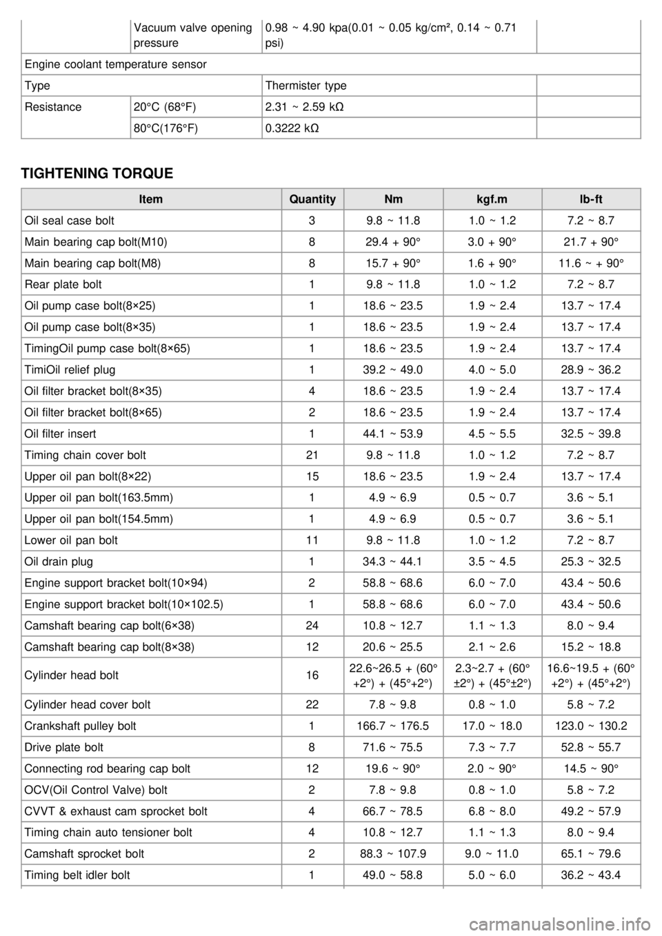
Vacuum valve opening
pressure0.98 ~ 4.90 kpa(0.01 ~ 0.05 kg/cm², 0.14 ~ 0.71
psi)
Engine coolant temperature sensor
Type Thermister type
Resistance 20°C (68°F) 2.31 ~ 2.59 kΩ
80°C(176°F) 0.3222 kΩ
TIGHTENING TORQUE
Item QuantityNmkgf.m lb- ft
Oil seal case bolt 39.8 ~ 11.8 1.0 ~ 1.27.2 ~ 8.7
Main bearing cap bolt(M10) 829.4 + 90° 3.0 + 90°21.7 + 90°
Main bearing cap bolt(M8) 815.7 + 90° 1.6 + 90°11.6 ~ + 90°
Rear plate bolt 19.8 ~ 11.8 1.0 ~ 1.27.2 ~ 8.7
Oil pump case bolt(8×25) 118.6 ~ 23.5 1.9 ~ 2.413.7 ~ 17.4
Oil pump case bolt(8×35) 118.6 ~ 23.5 1.9 ~ 2.413.7 ~ 17.4
TimingOil pump case bolt(8×65) 118.6 ~ 23.5 1.9 ~ 2.413.7 ~ 17.4
TimiOil relief plug 139.2 ~ 49.0 4.0 ~ 5.028.9 ~ 36.2
Oil filter bracket bolt(8×35) 418.6 ~ 23.5 1.9 ~ 2.413.7 ~ 17.4
Oil filter bracket bolt(8×65) 218.6 ~ 23.5 1.9 ~ 2.413.7 ~ 17.4
Oil filter insert 144.1 ~ 53.9 4.5 ~ 5.532.5 ~ 39.8
Timing chain cover bolt 219.8 ~ 11.8 1.0 ~ 1.27.2 ~ 8.7
Upper oil pan bolt(8×22) 1518.6 ~ 23.5 1.9 ~ 2.413.7 ~ 17.4
Upper oil pan bolt(163.5mm) 14.9 ~ 6.9 0.5 ~ 0.73.6 ~ 5.1
Upper oil pan bolt(154.5mm) 14.9 ~ 6.9 0.5 ~ 0.73.6 ~ 5.1
Lower oil pan bolt 119.8 ~ 11.8 1.0 ~ 1.27.2 ~ 8.7
Oil drain plug 134.3 ~ 44.1 3.5 ~ 4.525.3 ~ 32.5
Engine support bracket bolt(10×94) 258.8 ~ 68.6 6.0 ~ 7.043.4 ~ 50.6
Engine support bracket bolt(10×102.5) 158.8 ~ 68.6 6.0 ~ 7.043.4 ~ 50.6
Camshaft bearing cap bolt(6×38) 2410.8 ~ 12.7 1.1 ~ 1.38.0 ~ 9.4
Camshaft bearing cap bolt(8×38) 1220.6 ~ 25.5 2.1 ~ 2.615.2 ~ 18.8
Cylinder head bolt 1622.6~26.5 + (60°
+2°) + (45°+2°) 2.3~2.7 + (60°
±2°) + (45°±2°) 16.6~19.5 + (60°
+2°) + (45°+2°)
Cylinder head cover bolt 227.8 ~ 9.8 0.8 ~ 1.05.8 ~ 7.2
Crankshaft pulley bolt 1166.7 ~ 176.5 17.0 ~ 18.0123.0 ~ 130.2
Drive plate bolt 871.6 ~ 75.5 7.3 ~ 7.752.8 ~ 55.7
Connecting rod bearing cap bolt 1219.6 ~ 90° 2.0 ~ 90°14.5 ~ 90°
OCV(Oil Control Valve) bolt 27.8 ~ 9.8 0.8 ~ 1.05.8 ~ 7.2
CVVT & exhaust cam sprocket bolt 466.7 ~ 78.5 6.8 ~ 8.049.2 ~ 57.9
Timing chain auto tensioner bolt 410.8 ~ 12.7 1.1 ~ 1.38.0 ~ 9.4
Camshaft sprocket bolt 288.3 ~ 107.9 9.0 ~ 11.065.1 ~ 79.6
Timing belt idler bolt 149.0 ~ 58.8 5.0 ~ 6.036.2 ~ 43.4
Page 36 of 1575
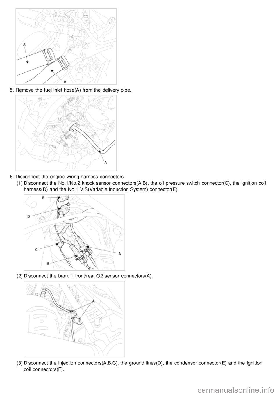
5.Remove the fuel inlet hose(A) from the delivery pipe.
6.Disconnect the engine wiring harness connectors.
(1) Disconnect the No.1/No.2 knock sensor connectors(A,B), the oil pressure switch connector(C), the ignition coil
harness(D) and the No.1 VIS(Variable Induction System) connector(E).
(2)Disconnect the bank 1 front/rear O2 sensor connectors(A).
(3)Disconnect the injection connectors(A,B,C), the ground lines(D), the condensor connector(E) and the Ignition
coil connectors(F).
Page 37 of 1575

(4)Disconnect the injection harness connector(A), the No.2 VIS(Variable Induction System) connector(B), the
No.1/No.2 OCV(Oil Control Valve) connectors(C,D) and the OTS(Oil Temperature Sensor) connector(E).
(5)Disconnect the MAPS(Manifold Absolute Pressure Sensor) connector(A), the ETC(Electronic Throttle Control)
connector(B) and the PCSV(Purge Control Solenoid Valve) connector(C).
(6)Disconnect the generator connector(A) and the air conditioning compressor connector(B).
Page 51 of 1575
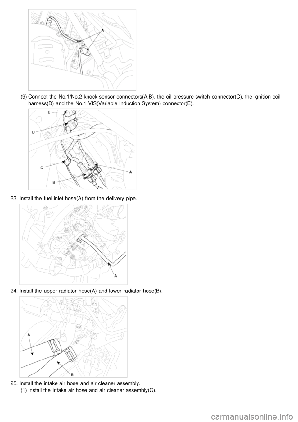
(9)Connect the No.1/No.2 knock sensor connectors(A,B), the oil pressure switch connector(C), the ignition coil
harness(D) and the No.1 VIS(Variable Induction System) connector(E).
23. Install the fuel inlet hose(A) from the delivery pipe.
24.Install the upper radiator hose(A) and lower radiator hose(B).
25.Install the intake air hose and air cleaner assembly.
(1) Install the intake air hose and air cleaner assembly(C).
Page 65 of 1575

(1)Disconnect the No.1/No.2 knock sensor connectors(A,B), the oil pressure switch connector(C), the ignition coil
harness(D) and the No.1 VIS(Variable Induction System) connector(E).
(2)Disconnect the bank 1 front/rear O2 sensor connectors(A).
(3)Disconnect the injection connectors(A,B,C), the ground lines(D), the condenser connector(E) and the Ignition
coil connectors(F).
(4)Disconnect the injection harness connector(A), the No.2 VIS(Variable Induction System) connector(B), the
No.1/No.2 OCV(Oil Control Valve) connectors(C,D) and the OTS(Oil Temperature Sensor) connector(E).
Page 125 of 1575
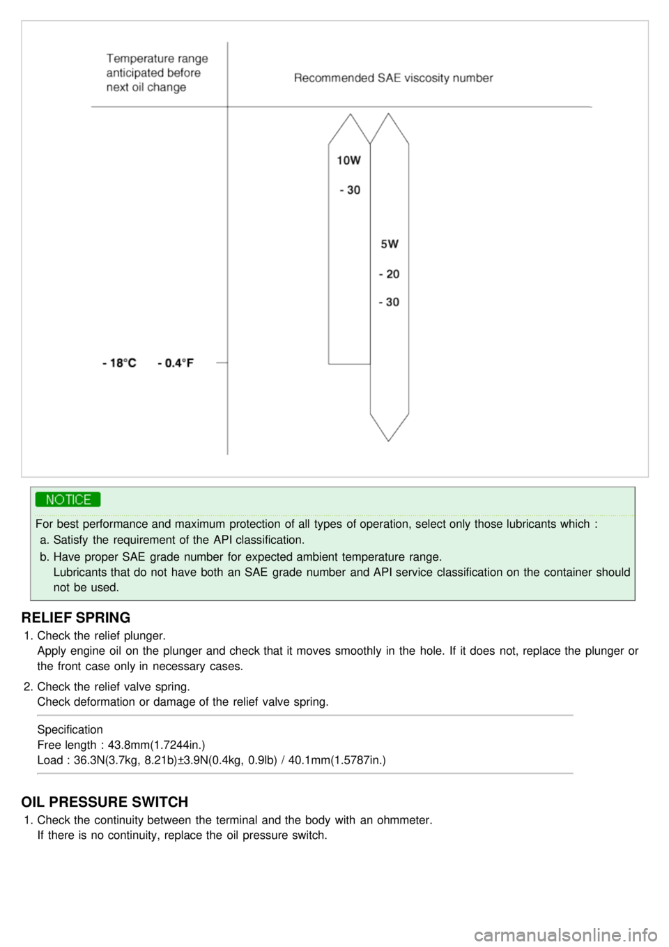
For best performance and maximum protection of all types of operation, select only those lubricants which :a. Satisfy the requirement of the API classification.
b. Have proper SAE grade number for expected ambient temperature range.
Lubricants that do not have both an SAE grade number and API service classification on the container should
not be used.
RELIEF SPRING
1.Check the relief plunger.
Apply engine oil on the plunger and check that it moves smoothly in the hole. If it does not, replace the plunger or
the front case only in necessary cases.
2. Check the relief valve spring.
Check deformation or damage of the relief valve spring.
Specification
Free length : 43.8mm(1.7244in.)
Load : 36.3N(3.7kg, 8.21b)±3.9N(0.4kg, 0.9lb) / 40.1mm(1.5787in.)
OIL PRESSURE SWITCH
1.Check the continuity between the terminal and the body with an ohmmeter.
If there is no continuity, replace the oil pressure switch.