warning light KIA CARNIVAL 2007 Workshop Manual
[x] Cancel search | Manufacturer: KIA, Model Year: 2007, Model line: CARNIVAL, Model: KIA CARNIVAL 2007Pages: 1575, PDF Size: 44.86 MB
Page 149 of 1575

2007 > 2.7L V6 GASOLINE >
TROUBLE SHOOTING
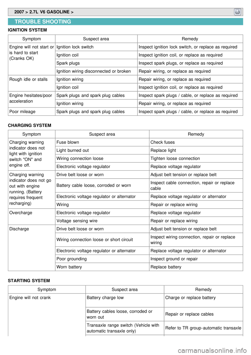
IGNITION SYSTEM
Symptom Suspect area Remedy
Engine will not start or
is hard to start
(Cranks OK) Ignition lock switch
Inspect ignition lock switch, or replace as required
Ignition coil Inspect ignition coil, or replace as required
Spark plugs Inspect spark plugs, or replace as required
Ignition wiring disconnected or broken Repair wiring, or replace as required
Rough idle or stalls Ignition wiring Repair wiring, or replace as required
Ignition coil Inspect ignition coil, or replace as required
Engine hesitates/poor
acceleration Spark plugs and spark plug cables
Inspect spark plugs / cable, or replace as required
Ignition wiring Repair wiring, or replace as required
Poor mileage Spark plugs and spark plug cables Inspect spark plugs / cable, or replace as required
CHARGING SYSTEM Symptom Suspect area Remedy
Charging warning
indicator does not
light with ignition
switch "ON" and
engine off. Fuse blown
Check fuses
Light burned out Replace light
Wiring connection loose Tighten loose connection
Electronic voltage regulator Replace voltage regulator
Charging warning
indicator does not go
out with engine
running. (Battery
requires frequent
recharging) Drive belt loose or worn
Adjust belt tension or replace belt
Battery cable loose, corroded or worn Inspect cable connection, repair or replace
cable
Electronic voltage regulator or alternator Replace voltage regulator or alternator
Wiring Repair or replace wiring
Overcharge Electronic voltage regulator Replace voltage regulator
Voltage sensing wire Repair or replace wiring
Discharge Drive belt loose or worn Adjust belt tension or replace belt
Wiring connection loose or short circuit Inspect wiring connection, repair or replace
wiring
Electronic voltage regulator or alternator Replace voltage regulator or alternator
Poor grounding Inspect ground or repair
Worn battery Replace battery
STARTING SYSTEM Symptom Suspect area Remedy
Engine will not crank Battery charge low Charge or replace battery
Battery cables loose, corroded or
worn out Repair or replace cables
Transaxle range switch (Vehicle with
automatic transaxle only) Refer to TR group - automatic transaxle
Page 160 of 1575

2007 > 2.7L V6 GASOLINE >
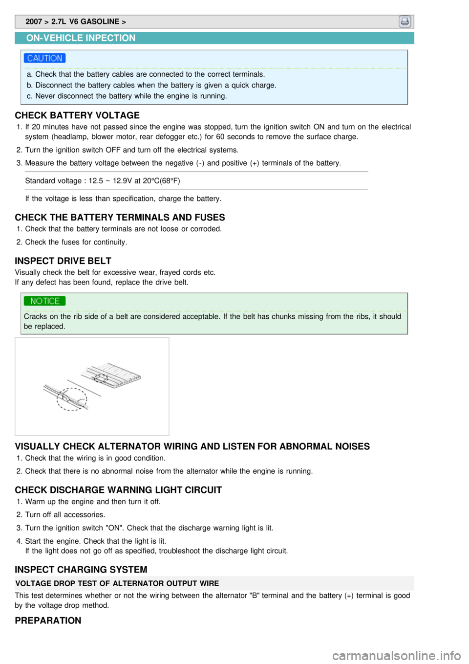
ON-VEHICLE INPECTION
a.Check that the battery cables are connected to the correct terminals.
b. Disconnect the battery cables when the battery is given a quick charge.
c. Never disconnect the battery while the engine is running.
CHECK BATTERY VOLTAGE
1.If 20 minutes have not passed since the engine was stopped, turn the ignition switch ON and turn on the electrical
system (headlamp, blower motor, rear defogger etc.) for 60 seconds to remove the surface charge.
2. Turn the ignition switch OFF and turn off the electrical systems.
3. Measure the battery voltage between the negative ( - ) and positive (+) terminals of the battery.
Standard voltage : 12.5 ~ 12.9V at 20°C(68°F)
If the voltage is less than specification, charge the battery.
CHECK THE BATTERY TERMINALS AND FUSES
1.Check that the battery terminals are not loose or corroded.
2. Check the fuses for continuity.
INSPECT DRIVE BELT
Visually check the belt for excessive wear, frayed cords etc.
If any defect has been found, replace the drive belt.
Cracks on the rib side of a belt are considered acceptable. If the belt has chunks missing from the ribs, it should
be replaced.
VISUALLY CHECK ALTERNATOR WIRING AND LISTEN FOR ABNORMAL NOISES
1.Check that the wiring is in good condition.
2. Check that there is no abnormal noise from the alternator while the engine is running.
CHECK DISCHARGE WARNING LIGHT CIRCUIT
1.Warm up the engine and then turn it off.
2. Turn off all accessories.
3. Turn the ignition switch "ON". Check that the discharge warning light is lit.
4. Start the engine. Check that the light is lit.
If the light does not go off as specified, troubleshoot the discharge light circuit.
INSPECT CHARGING SYSTEM
VOLTAGE DROP TEST OF ALTERNATOR OUTPUT WIRE
This test determines whether or not the wiring between the alternator "B" terminal and the battery (+) terminal is good
by the voltage drop method.
PREPARATION
Page 816 of 1575

2007 > 2.7L V6 GASOLINE >
DESCRIPTION
The primary purpose of the SRSCM (Supplemental Restraints System Control Module) is to discriminate between an
event that warrants restraint system deployment and an event that does not. The SRSCM must decide whether to
deploy the restraint system or not. After determining that pretensioners and/or airbag deployment is required, the
SRSCM must supply sufficient power to the pretensioners and airbag igniters to initiate deployment. The SRSCM
determines that an impact may require deployment of the pretensioners and airbags from data obtained from impact
sensors and other components in conjunction with a safing function. The SRSCM will not be ready to detect a crash or
to activate the restraint system devices until the signals in the SRSCM circuitry stabilize. It is possible that the SRSCM
could activate the safety restraint devices in approximately 2 seconds but is guaranteed to fully function after prove-
out is completed. The SRSCM must perform a diagnostic routine and light a system readiness indicator at key - on. The
system must perform a continuous diagnostic routine and provide fault annunciation through a warning lamp indicator
in the event of fault detection. A serial diagnostic communication interface will be used to facilitate servicing of the
restraint control system.
Page 926 of 1575

18Voltage for hybrid ECU 1 A500 mA 60200
5,10,17,19 signal wheel speed sensor FL,
FR, RL,RR
6 mA
16 mA 250200 to
ground 1.5M to bat
16,9,6,8 Voltage supply for the active
wheel speed sensor FL,FR,
RL, RR 6 mA
16 mA 250200 to
ground 1.5M to bat
14,24 wheel speed sensor output
(FR, RL) 20 mA
10 mA 250200
11 Diagnostic wire K 6 mA3 mA 250200
22 ABS - warning lamp actuation 30 mA5 mA 250200
12 EBD- warning lamp actuation 30 mA5 mA 250200
20 brake light switch 10 mA5 mA 250200
15 CAN Low 30 mA20 mA 250200
26 CAN High 30 mA20 mA 250200
ABS HECU CONNECTOR Connector terminal SpecificationCondition
Number Description
1 Ground for recirculation pump Current range: Min.10A
Max.20~39A Always
4 Ground for solenoid valves and
ECU Current range: Min.2.5A
Max.5~15A Always
2 Voltage supply for pump motor
Battery voltageAlways
3 Voltage supply for solenoid valves
16 Voltage supply for the active
wheel speed sensor FL,FR, RL, RR Battery voltage
IG ON
9
6
8
5
signal wheel speed sensor FL, FR, RL,RR Voltage(High) : 0.89~1.26 V
Voltage (Low) : 0.44~0.63 V On driving
10
17
19
11
Diagnostic wire K Voltage (High)
≥ 0.8 * IG ON
Voltage (Low) ≤ 0.2 * IG ON On SCAN TOOL
communication
18 Voltage for hybrid ECU Battery voltageKEY ON/OFF
20 Brake light switch Voltage (High)
≥ 0.8 * IG ON
Voltage (Low) ≤ 0.3 * IG ON BRAKE ON/OFF
SENSOR OUTPUT ON SCAN TOOL(ABS) Description AbbreviationUnitRemarks
1 Vehicle speed sensor VEH. SPDKm/h
2 Battery voltage BATT. VOLV
3 FL Wheel speed sensor FL WHEELKm/h
Page 937 of 1575

c.Stop lamp switch circuit.
d. Check the hydraulic circuit for leakage.
Communication with Scan tool is not possible.
(Communication with any system is not possible) a.
Power source circuit
b. Diagnosis line
Communication with Scan tool is not possible.
(Communication with ABS only is not possible) a.
Power source circuit
b. Diagnosis line
c. HECU
When ignition key is turned ON (engine OFF), the ABS
warning lamp does not light up. a.
ABS warning lamp circuit
b. HECU
Even after the engine is started, the ABS warning lamp
remains ON. a.
ABS warning lamp circuit
b. HECU
During ABS operation, the brake pedal may vibrate or may not be able to be depressed. Such phenomena are
due to intermittent changes in hydraulic pressure inside the brake line to prevent the wheels from locking and is
not an abnormality.
DETECTING CONDITION
Trouble Symptoms Possible Cause
Brake operation varies depending on driving conditions and road
surface conditions, so diagnosis can be difficult.However if a normal
DTC is displayed, check the following probable cause. When the
problem is still occurring, replace the ABS control module. a.
Inoperative power source circuit
b. Inoperative wheel speed sensor circuit
c. Inoperative hydraulic circuit for leakage
d. Inoperative HECU
INSPECTION PROCEDURES
DTC INSPECTION
1. Connect the Scan Tool with the data link connector and turn the ignition switch ON.
2. Verify that the system is operating to specifications.
Is the system operating to specifications ?
▶ Check the power source circuit.
▶ Erase the DTC and recheck using Scan Tool.
CHECK THE POWER SOURCE CIRCUIT.
1. Disconnect the connector from the ABS control module.
2. Turn the ignition switch ON, measure the voltage between terminal 18 of the ABS control module harness side
connector and body ground.
Specification: approximately B+
Is the voltage within specification?
▶ Check the ground circuit.
▶ Check the harness or connector between the fuse (10A) in the engine compartment junction block and the ABS
control module. Repair if necessary.
Page 942 of 1575

DETECTING CONDITIONTrouble Symptoms Possible Cause
When current flows in the HECU the ABS warning lamp turns from
ON to OFF as the initial check.Therefore if the lamp does not light up,
the cause may be an open in the lamp power supply circuit, a blown
bulb, an open in the both circuits between the ABS warning lamp and
the HECU, and the inoperative HECU. a.
Inoperative ABS warning lamp bulb
b. Blown No.2 fuse (10A) in the engine
compartment junction block
c. Inoperative ABS warning lamp module
d. Inoperative HECU
INSPECTION PROCEDURES
PROBLEM VERIFICATION
Disconnect the connector from the ABS control module and turn the ignition switch ON.
Does the ABS warning lamp light up?
▶ It is normal. Recheck the ABS control module.
▶ Check the power source for the ABS warning lamp.
CHECK THE POWER SOURCE FOR THE ABS WARNING LAMP
1. Disconnect the instrument cluster connector and turn the ignition switch ON.
2. Measure the voltage between terminal 8 of the cluster harness side connector and body ground.
Specification: approximately B+
Is voltage within specification?
▶ Repair bulb or instrument cluster assembly.
▶ Check for blown fuse.
Page 943 of 1575

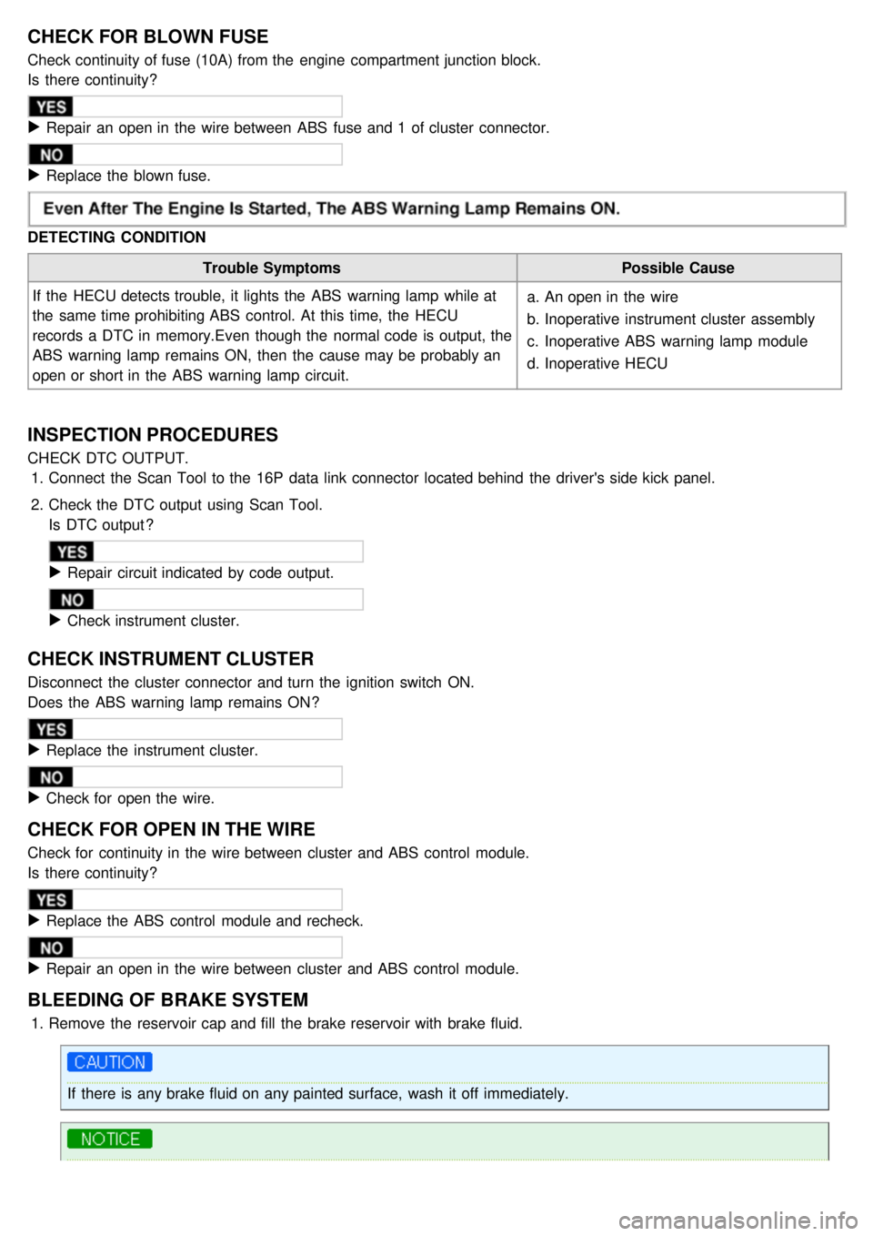
CHECK FOR BLOWN FUSE
Check continuity of fuse (10A) from the engine compartment junction block.
Is there continuity?
▶ Repair an open in the wire between ABS fuse and 1 of cluster connector.
▶ Replace the blown fuse.
DETECTING CONDITION
Trouble Symptoms Possible Cause
If the HECU detects trouble, it lights the ABS warning lamp while at
the same time prohibiting ABS control. At this time, the HECU
records a DTC in memory.Even though the normal code is output, the
ABS warning lamp remains ON, then the cause may be probably an
open or short in the ABS warning lamp circuit. a.
An open in the wire
b. Inoperative instrument cluster assembly
c. Inoperative ABS warning lamp module
d. Inoperative HECU
INSPECTION PROCEDURES
CHECK DTC OUTPUT.
1. Connect the Scan Tool to the 16P data link connector located behind the driver's side kick panel.
2. Check the DTC output using Scan Tool.
Is DTC output ?
▶ Repair circuit indicated by code output.
▶ Check instrument cluster.
CHECK INSTRUMENT CLUSTER
Disconnect the cluster connector and turn the ignition switch ON.
Does the ABS warning lamp remains ON?
▶ Replace the instrument cluster.
▶ Check for open the wire.
CHECK FOR OPEN IN THE WIRE
Check for continuity in the wire between cluster and ABS control module.
Is there continuity?
▶ Replace the ABS control module and recheck.
▶ Repair an open in the wire between cluster and ABS control module.
BLEEDING OF BRAKE SYSTEM
1. Remove the reservoir cap and fill the brake reservoir with brake fluid.
If there is any brake fluid on any painted surface, wash it off immediately.
Page 946 of 1575

DTCDESCRIPTION WARNING LAMP
REMARK
ABS EBDESC
C1101 BATTERY VOLTAGE HIGH ООО
C1102 BATTERY VOLTAGE LOW ОО
C1200 FL WHEEL SPEED SENSOR- OPEN/SHORT ОО
C1201 FL WHEEL SENSOR- RANGE/ PERFORMANCE ОО
C1202 FL WHEEL WHEEL SPEED SENSOR- NO SIGNAL ОО
C1203 FR WHEEL SPEED SENSOR- OPEN/SHORT ОО
C1204 FR WHEEL SENSOR- RANGE/ PERFORMANCE ОО
C1205 FR WHEEL SPEED SENSOR- NO SIGNAL ОО
C1206 RL WHEEL SPEED SENSOR- OPEN/SHORT ОО
C1207 RL WHEEL SENSOR- RANGE/ PERFORMANCE ОО
C1208 RL WHEEL SPEED SENSOR- NO SIGNAL ОО
C1209 RR WHEEL SPEED SENSOR- OPEN/SHORT ОО
C1210 RR WHEEL SENSOR- RANGE/ PERFORMANCE ОО
C1211 RR WHEEL SPEED SENSOR- NO SIGNAL ОО
C1213 WHEEL SPEED FREQUENCY ERROR ОО
C1235 PRESSURE SENSOR- ELECTRICAL ОESP
C1237 PRESSURE SENSOR- SIGNAL FAULT ОESP
C1260 STEERING ANGLE SENSOR- SIGNAL ОESP
C1261 STEERING ANGLE SENSOR NOT CALIBRATED ОESP
C1282 YAW RATE & LATERAL G SENSOR- ELECTRICAL ОESP
C1283 YAW RATE & LATERAL G SENSOR- SIGNAL ОESP
C1503 ESP SWITCH ERROR ОESP
C1513 BRAKE LIGHT SWITCH MALFUNCTION О
C1604 ECU HARDWARE ERROR ООО
C1605 CAN CONTROL HARDWARE ERROR ОESP
C1611 CAN TIME OUT- PCM(ECM) ОESP
C1612 CAN TIME OUT- PCM(TCM) ОESP
C1616 CAN BUS OFF ОESP
C1623 CAN TIMEOUT STEERING ANGLE SENSOR ОESP
C1625 CAN TIME OUT- ESP ОESP
C1626 IMPLAUSIBLE CONTROL ООESP
C1702 VARIANT CODING ООО ESP
C2112 VALVE RELAY MALFUNCTION ООО
C2308 FL INLET VALVE MALFUNCTION ООО
C2312 FL OUTLET VALVE MALFUNCTION ООО
C2316 FR INLET VALVE MALFUNCTION ООО
C2320 FR OUTLET VALVE MALFUNCTION ООО
C2324 RL INLET VALVE MALFUNCTION ООО
C2328 RL OUTLET VALVE MALFUNCTION ООО
Page 961 of 1575

2007 > 2.7L V6 GASOLINE >
DESCRIPTION
The EBD system (Electronic Brake force Distribution) as a sub- system of the ABS system is to control the effective
adhesion utilization by the rear wheels.
It further utilizes the efficiency of highly developed ABS equipment by controlling the slip of the rear wheels in the
partial braking range.
The brake force is moved even closer to the optimum and controlled electronically, thus dispensing with the need for
the proportioning valve.
The proportioning valve, because of a mechanical device, has limitations to achieve an ideal brake force distribution
tothe rear wheels as well as to carry out the flexible brake force distribution proportioning to the vehicle load or weight
increasing. And in the event of malfunctioning, driver cannot notice whether it fails or not.
EBD controlled by the ABS Control Module, calculates the slip ratio of each wheel at all times and controls the brake
pressure of the rear wheels not to exceed that of the front wheels.
If the EBD fails, the EBD warning lamp (Parking brake lamp) lights up.
ADVANTAGES
a.Function improvement of the base - brake system.
b. Compensation for the different friction coefficients.
c. Elimination of the proportioning valve.
d. Failure recognition by the warning lamp.
Comparison between Proportioning valve and EBD
Page 1211 of 1575

2007 > 2.7L V6 GASOLINE >
DESCRIPTION
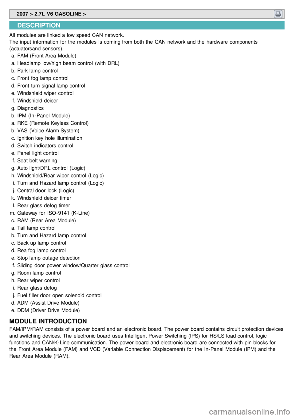
All modules are linked a low speed CAN network.
The input information for the modules is coming from both the CAN network and the hardware components
(actuatorsand sensors).
a. FAM (Front Area Module)
a. Headlamp low/high beam control (with DRL)
b. Park lamp control
c. Front fog lamp control
d. Front turn signal lamp control
e. Windshield wiper control
f. Windshield deicer
g. Diagnostics
b. IPM (In - Panel Module)
a. RKE (Remote Keyless Control)
b. VAS (Voice Alarm System)
c. Ignition key hole illumination
d. Switch indicators control
e. Panel light control
f. Seat belt warning
g. Auto light/DRL control (Logic)
h. Windshield/Rear wiper control (Logic)
i. Turn and Hazard lamp control (Logic)
j. Central door lock (Logic)
k. Windshield deicer timer
l. Rear glass defog timer
m. Gateway for ISO- 9141 (K- Line)
c. RAM (Rear Area Module)
a. Tail lamp control
b. Turn and Hazard lamp control
c. Back up lamp control
d. Rea fog lamp control
e. Stop lamp outage detection
f. Sliding door power window/Quarter glass control
g. Room lamp control
h. Rear wiper control
i. Rear glass defog
j. Fuel filler door open solenoid control
d. ADM (Assist Drive Module)
e. DDM (Driver Drive Module)
MODULE INTRODUCTION
FAM/IPM/RAM consists of a power board and an electronic board. The power board contains circuit protection devices
and switching devices. The electronic board uses Intelligent Power Switching (IPS) for HS/LS load control, logic
functions and CAN/K- Line communication. The power board and electronic board are connected with pin blocks for
the Front Area Module (FAM) and VCD (Variable Connection Displacement) for the In- Panel Module (IPM) and the
Rear Area Module (RAM).