sensor KIA CEED 2013 Owner's Manual
[x] Cancel search | Manufacturer: KIA, Model Year: 2013, Model line: CEED, Model: KIA CEED 2013Pages: 1168, PDF Size: 48.01 MB
Page 182 of 1168
4 103
Features of your vehicle
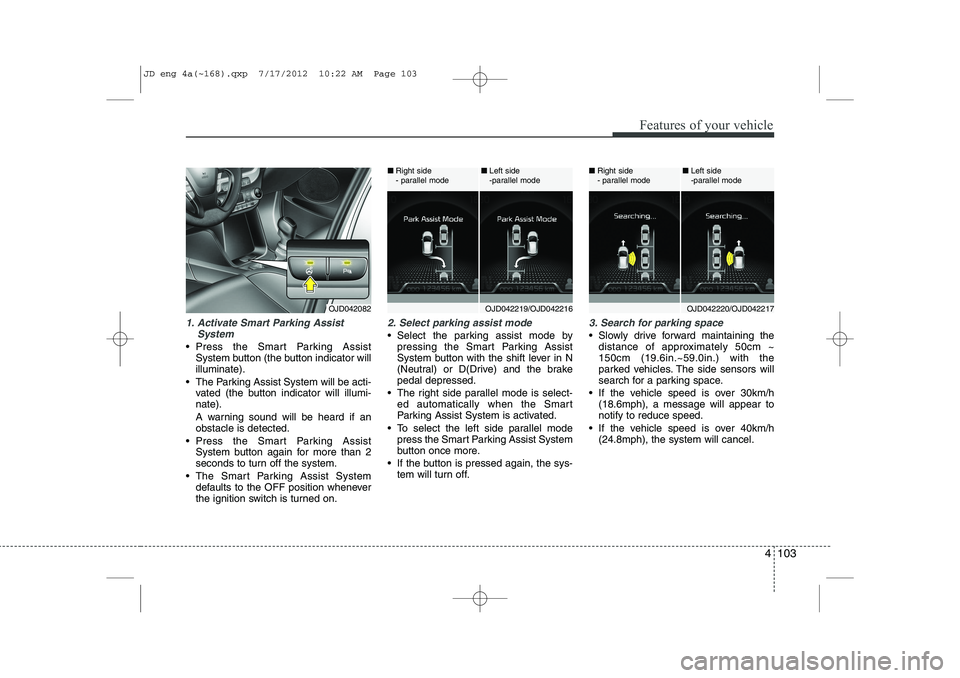
1. Activate Smart Parking AssistSystem
Press the Smart Parking AssistSystem button (the button indicator will illuminate).
The Parking Assist System will be acti- vated (the button indicator will illumi-nate).
A warning sound will be heard if an obstacle is detected.
Press the Smart Parking Assist System button again for more than 2
seconds to turn off the system.
The Smart Parking Assist System defaults to the OFF position whenever
the ignition switch is turned on.
2. Select parking assist mode
Select the parking assist mode bypressing the Smart Parking Assist
System button with the shift lever in N
(Neutral) or D(Drive) and the brakepedal depressed.
The right side parallel mode is select- ed automatically when the Smart
Parking Assist System is activated.
To select the left side parallel mode press the Smart Parking Assist System
button once more.
If the button is pressed again, the sys- tem will turn off.
3. Search for parking space
Slowly drive forward maintaining thedistance of approximately 50cm ~ 150cm (19.6in.~59.0in.) with the
parked vehicles. The side sensors will
search for a parking space.
If the vehicle speed is over 30km/h (18.6mph), a message will appear tonotify to reduce speed.
If the vehicle speed is over 40km/h (24.8mph), the system will cancel.
OJD042082OJD042219/OJD042216
■
Right side
- parallel mode ■
Left side
-parallel modeOJD042220/OJD042217
■
Right side
- parallel mode ■
Left side
-parallel mode
JD eng 4a(~168).qxp 7/17/2012 10:22 AM Page 103
Page 191 of 1168
Features of your vehicle
112
4
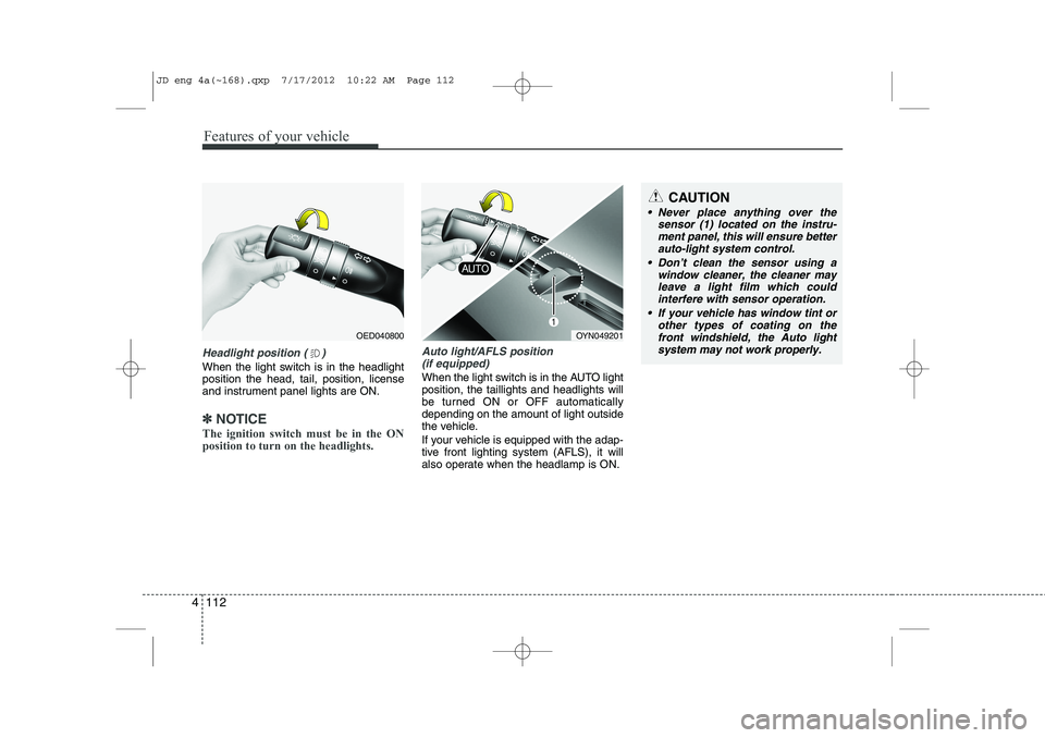
Headlight position ( )
When the light switch is in the headlight position the head, tail, position, license
and instrument panel lights are ON.
✽✽
NOTICE
The ignition switch must be in the ON position to turn on the headlights.
Auto light/AFLS position (if equipped)
When the light switch is in the AUTO light position, the taillights and headlights will
be turned ON or OFF automaticallydepending on the amount of light outside
the vehicle.
If your vehicle is equipped with the adap-
tive front lighting system (AFLS), it will
also operate when the headlamp is ON.
OYN049201
CAUTION
Never place anything over the sensor (1) located on the instru-
ment panel, this will ensure betterauto-light system control.
Don’t clean the sensor using a window cleaner, the cleaner may
leave a light film which couldinterfere with sensor operation.
If your vehicle has window tint or other types of coating on thefront windshield, the Auto light
system may not work properly.
OED040800
JD eng 4a(~168).qxp 7/17/2012 10:22 AM Page 112
Page 198 of 1168
4 119
Features of your vehicle
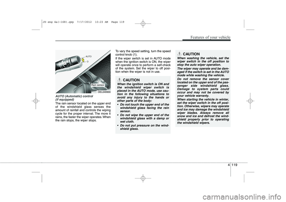
AUTO (Automatic) control (if equipped)
The rain sensor located on the upper end of the windshield glass senses the
amount of rainfall and controls the wiping
cycle for the proper interval. The more it
rains, the faster the wiper operates. When
the rain stops, the wiper stops. To vary the speed setting, turn the speedcontrol knob (1).
If the wiper switch is set in AUTO mode
when the ignition switch is ON, the wiper
will operate once to perform a self-check
of the system. Set the wiper to off posi-
tion when the wiper is not in use.
CAUTION
When the ignition switch is ON and
the windshield wiper switch isplaced in the AUTO mode, use cau-
tion in the following situations toavoid any injury to the hands orother parts of the body:
Do not touch the upper end of the windshield glass facing the rain
sensor.
Do not wipe the upper end of the windshield glass with a damp orwet cloth.
Do not put pressure on the wind- shield glass.
OEL049900
Rain sensor
CAUTION
When washing the vehicle, set thewiper switch in the off position to
stop the auto wiper operation.
The wiper may operate and be dam-aged if the switch is set in the AUTOmode while washing the vehicle.
Do not remove the sensor coverlocated on the upper end of the pas- senger side windshield glass.Damage to system parts could occur and may not be covered by
your vehicle warranty.
When starting the vehicle in winter,set the wiper switch in the off posi-tion. Otherwise, wipers may operate
and ice may damage the windshieldwiper blades. Always remove all snow and ice and defrost the wind-shield properly prior to operating
the windshield wipers.
JD eng 4a(~168).qxp 7/17/2012 10:23 AM Page 119
Page 229 of 1168
Features of your vehicle
150
4
This indicator illuminates
when the auto defoggingsystem senses the moistureof inside the windshield and
operates.
If more moisture is in the vehicle, higher
steps operate as follow.
Step 1 : Operating the air conditioning
Step 2 : Outside air position
Step 3 : Blowing air flow toward the wind- shield
Step 4 : Increasing air flow toward the windshield
If your vehicle is equipped with the auto
defogging system, it is automatically acti-
vated when the conditions are met.
However, if you would like to cancel the
auto defogging system, press the front
defroster button 4 times within 2 seconds
while pressing the AUTO button. The
indicator will blink 3 times to notify you
that the system is cancelled. To use the
auto defogging system again, follow the
procedures mentioned above.
If the battery has been disconnected or
discharged, it resets to the auto defog-
ging status.✽✽ NOTICE
If the A/C off is manually selected while the auto defogging system is on, the auto
defogging indicator will blink 3 times to
give notice that the A/C off can not beselected.
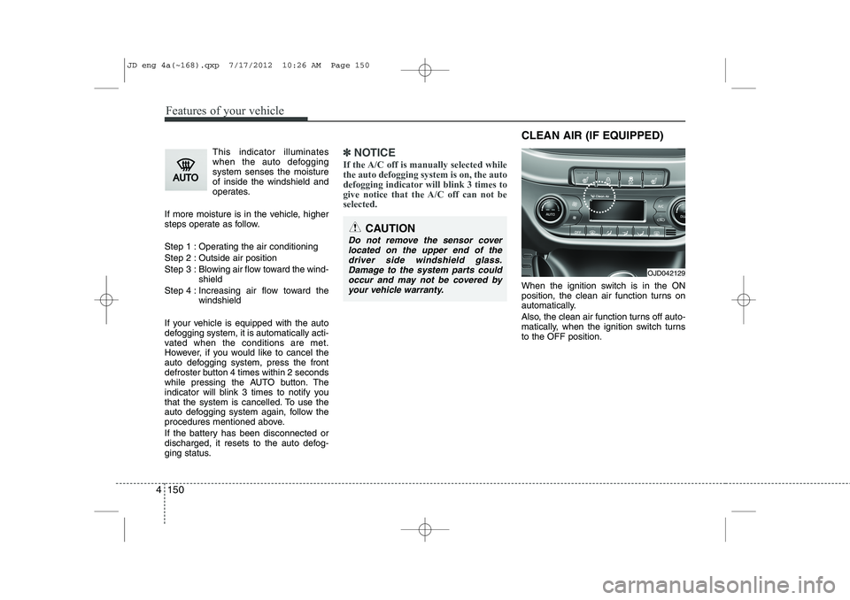
When the ignition switch is in the ON
position, the clean air function turns on
automatically.
Also, the clean air function turns off auto-
matically, when the ignition switch turnsto the OFF position.
CAUTION
Do not remove the sensor cover located on the upper end of thedriver side windshield glass.Damage to the system parts could occur and may not be covered by
your vehicle warranty.
OJD042129
CLEAN AIR (IF EQUIPPED)
JD eng 4a(~168).qxp 7/17/2012 10:26 AM Page 150
Page 360 of 1168
519
Driving your vehicle
ISG system malfunction
The system may not operate when:
The ISG related sensors or system error
occurs.
The following will happen:
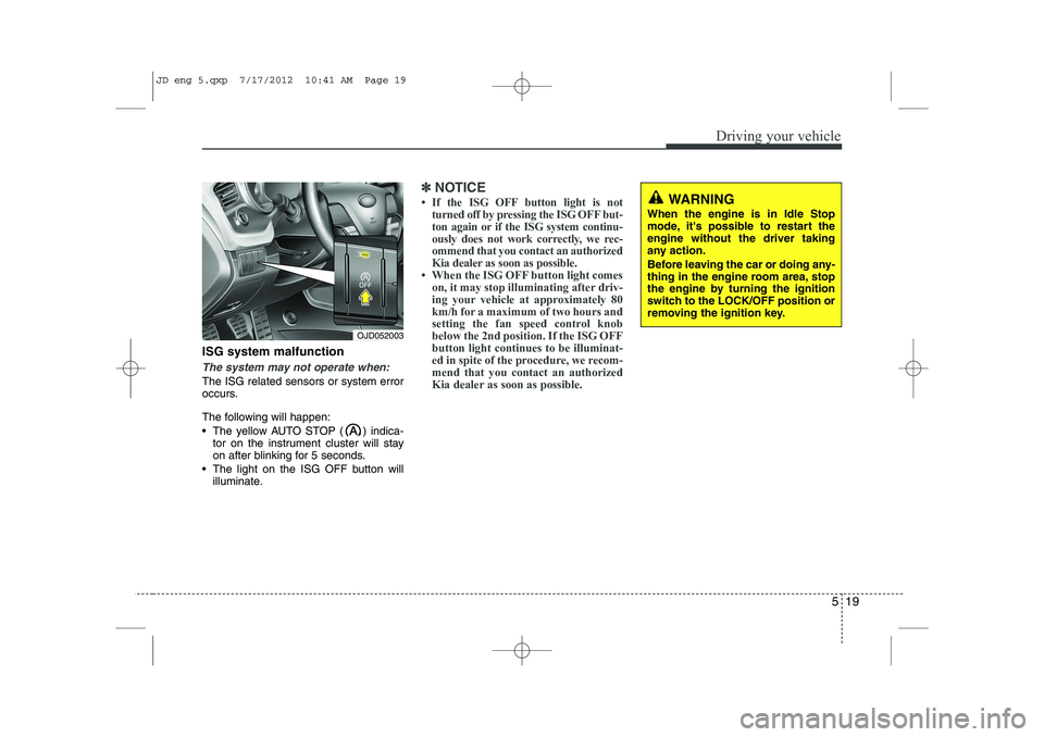
The yellow AUTO STOP ( ) indica-tor on the instrument cluster will stay
on after blinking for 5 seconds.
The light on the ISG OFF button will illuminate.
✽✽ NOTICE
Page 400 of 1168
559
Driving your vehicle
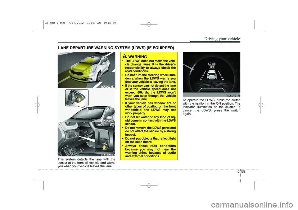
This system detects the lane with the
sensor at the front windshield and warns
you when your vehicle leaves the lane.To operate the LDWS, press the switch
with the ignition in the ON position. The
indicator illuminates on the cluster. To
cancel the LDWS, press the switchagain.
LANE DEPARTURE WARNING SYSTEM (LDWS) (IF EQUIPPED)
WARNING
The LDWS does not make the vehi- cle change lanes. It is the driver's
responsibility to always check the
road conditions.
Do not turn the steering wheel sud- denly, when the LDWS warns you
that your vehicle is leaving the lane.
If the sensor can not detect the lane or if the vehicle speed does not
exceed 60km/h, the LDWS won't
warn you even though the vehicle
leaves the lane.
If your vehicle has window tint or other types of coating on the front
windshield, the LDWS may not
work properly.
Do not let water or any kind of liq- uid come in contact with the LDWS
sensor.
Do not remove the LDWS parts and do not affect the sensor by a strongimpact.
Do not put objects that reflect light on the dash board.
Always check road conditions because you may not hear the
warning chime because of audio
and external conditions.
OJD052030
OJD052029
OJD042178
OJD052028
JD eng 5.qxp 7/17/2012 10:43 AM Page 59
Page 401 of 1168
Driving your vehicle
60
5
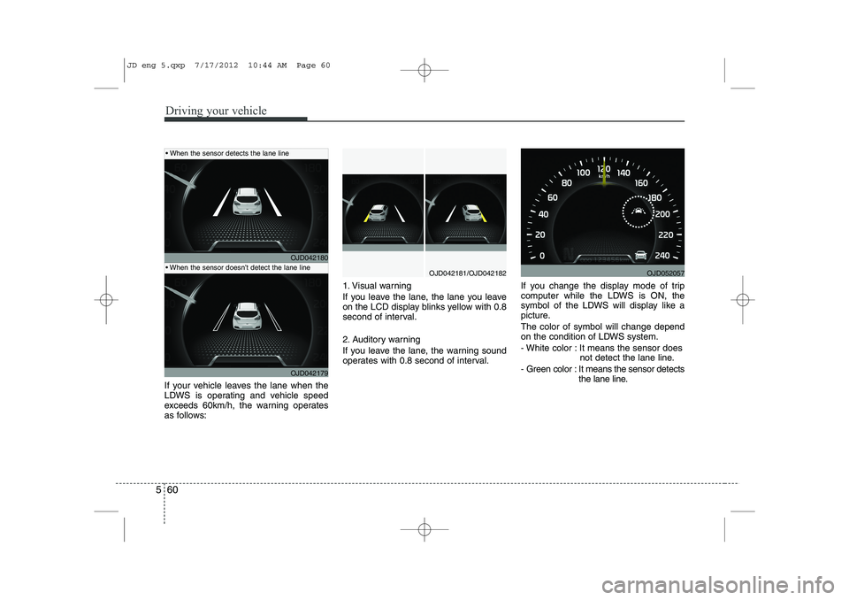
If your vehicle leaves the lane when the
LDWS is operating and vehicle speed
exceeds 60km/h, the warning operates
as follows: 1. Visual warning
If you leave the lane, the lane you leave
on the LCD display blinks yellow with 0.8
second of interval.
2. Auditory warning
If you leave the lane, the warning sound
operates with 0.8 second of interval.
If you change the display mode of trip
computer while the LDWS is ON, the
symbol of the LDWS will display like a
picture. The color of symbol will change depend
on the condition of LDWS system.
- White color : It means the sensor does
not detect the lane line.
- Green color : It means the sensor detects the lane line.
OJD042180
OJD042179
OJD042181/OJD042182
When the sensor detects the lane line
When the sensor doesn’t detect the lane lineOJD052057
JD eng 5.qxp 7/17/2012 10:44 AM Page 60
Page 402 of 1168
561
Driving your vehicle
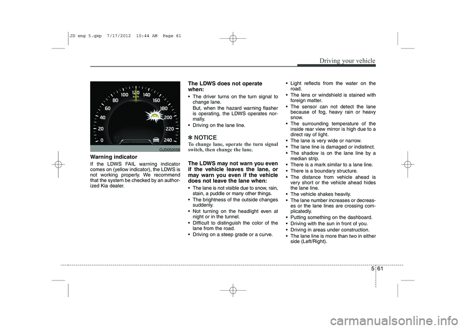
Warning indicator
If the LDWS FAIL warning indicator
comes on (yellow indicator), the LDWS is
not working properly. We recommend
that the system be checked by an author-
ized Kia dealer.The LDWS does not operate when:
The driver turns on the turn signal to
change lane.
But, when the hazard warning flasher
is operating, the LDWS operates nor-
mally.
Driving on the lane line.
✽✽ NOTICE
To change lane, operate the turn signal switch, then change the lane.
The LDWS may not warn you even
if the vehicle leaves the lane, or
may warn you even if the vehicle
does not leave the lane when:
The lane is not visible due to snow, rain, stain, a puddle or many other things.
The brightness of the outside changes suddenly.
Not turning on the headlight even at night or in the tunnel.
Difficult to distinguish the color of the lane from the road.
Driving on a steep grade or a curve. Light reflects from the water on the
road.
The lens or windshield is stained with foreign matter.
The sensor can not detect the lane because of fog, heavy rain or heavy
snow.
The surrounding temperature of the inside rear view mirror is high due to a
direct ray of light.
The lane is very wide or narrow.
The lane line is damaged or indistinct.
The shadow is on the lane line by a median strip.
There is a mark similar to a lane line.
There is a boundary structure.
The distance from vehicle ahead is very short or the vehicle ahead hides
the lane line.
The vehicle shakes heavily.
The lane number increases or decreas- es or the lane lines are crossing com-
plicatedly.
Putting something on the dashboard.
Driving with the sun in front of you.
Driving in areas under construction.
The lane line is more than two in either side (Left/Right).
OJD052056
JD eng 5.qxp 7/17/2012 10:44 AM Page 61
Page 427 of 1168
What to do in an emergency
6
6
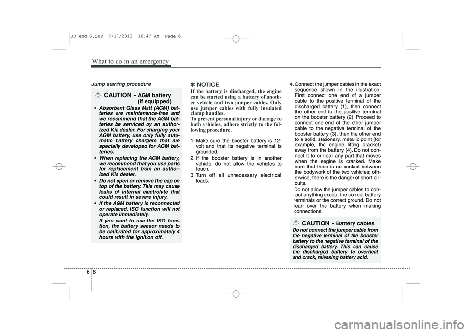
Jump starting procedure ✽✽
NOTICE
If the battery is discharged, the engine can be started using a battery of anoth-
er vehicle and two jumper cables. Only
use jumper cables with fully insulatedclamp handles.
To prevent personal injury or damage to
both vehicles, adhere strictly to the fol-
lowing procedure.
1. Make sure the booster battery is 12- volt and that its negative terminal is
grounded.
2. If the booster battery is in another vehicle, do not allow the vehicles totouch.
3. Turn off all unnecessary electrical loads. 4. Connect the jumper cables in the exact
sequence shown in the illustration.First connect one end of a jumper
cable to the positive terminal of the
discharged battery (1), then connect
the other end to the positive terminal
on the booster battery (2). Proceed toconnect one end of the other jumper
cable to the negative terminal of the
booster battery (3), then the other end
to a solid, stationary, metallic point (for
example, the engine lifting bracket)
away from the battery (4). Do not con-
nect it to or near any part that moves
when the engine is cranked. Make
sure that there is no contact between
the bodywork of the two vehicles; oth-
erwise, there is the danger of short cir-
cuits.
Do not allow the jumper cables to con-
tact anything except the correct battery
terminals or the correct ground. Do not
lean over the battery when making
connections.
CAUTION - Battery cables
Do not connect the jumper cable from
the negative terminal of the booster battery to the negative terminal of thedischarged battery. This can cause
the discharged battery to overheat and crack, releasing battery acid.
CAUTION -AGM battery (if equipped)
Absorbent Glass Matt (AGM) bat-
teries are maintenance-free andwe recommend that the AGM bat-
teries be serviced by an author-ized Kia dealer. For charging yourAGM battery, use only fully auto-
matic battery chargers that arespecially developed for AGM bat-teries.
When replacing the AGM battery, we recommend that you use parts
for replacement from an author- ized Kia dealer.
Do not open or remove the cap on top of the battery. This may cause
leaks of internal electrolyte that could result in severe injury.
If the AGM battery is reconnected or replaced, ISG function will notoperate immediately.
If you want to use the ISG func-tion, the battery sensor needs to be calibrated for approximately 4hours with the ignition off.
JD eng 6.QXP 7/17/2012 10:47 AM Page 6
Page 443 of 1168
What to do in an emergency
22
6
Technical Data
System voltage: DC 12 V
Working voltage: DC 10 - 15 V
Amperage rating: max. 15 A
Suitable for use at temperatures:
-30 ~ +70°C (-22 ~ +158°F)
Max. working pressure: 6 bar (87 psi)
Size (for 15´´, 16´´ wheel)
Compressor: 170 x 150 x 60 mm (6.7 x 5.9 x 2.4 in.)
Sealant bottle: 85 x 77 ø mm (3.3 x 3.0 ø in.)
Compressor weight: 0.8 kg (1.8 lbs)
Sealant volume: 200 ml (12.2 cu. in.)
Size (for 17´´ wheel)
Compressor: 168 x 150 x 68 mm (6.6 x 5.9 x 2.7 in.)
Sealant bottle: 104 x ø 85 mm (4.1 x ø 3.3 in.)
Compressor weight: 1.05 kg (2.31 lbs)
Sealant volume: 300 ml (18.3 cu. in.) ❈
Sealing compound and spare
parts can be obtained and
replaced at an authorized vehicle
or tire dealer. Empty sealing com-
pound bottles may be disposed of
at home. Liquid residue from thesealing compound should be dis-
posed of by your vehicle or tiredealer or in accordance with local
waste disposal regulations.CAUTION - TPMS (if equipped )
When using Tire Mobility Kit, the
tire sealant can damage the tirepressure sensor. After using the Tire Mobility Kit, we recommendthat the tire pressure sensor bechecked by an authorized Kia dealer.
JD eng 6.QXP 7/17/2012 10:47 AM Page 22