turn signal KIA CEED 2014 Owner's Manual
[x] Cancel search | Manufacturer: KIA, Model Year: 2014, Model line: CEED, Model: KIA CEED 2014Pages: 1206, PDF Size: 50.15 MB
Page 602 of 1206
Index
12
I
Tilt and telescopic steering . . . . . . . . . . . . . . . . . . . 4-38
Storage compartment . . . . . . . . . . . . . . . . . . . . . . . . 4-152 Center console storage . . . . . . . . . . . . . . . . . . . . . . 4-152
Cool box . . . . . . . . . . . . . . . . . . . . . . . . . . . . . . . . . . 4-153
Glove box . . . . . . . . . . . . . . . . . . . . . . . . . . . . . . . . . 4-153
Luggage side tray . . . . . . . . . . . . . . . . . . . . . . . . . 4-155
Luggage tray . . . . . . . . . . . . . . . . . . . . . . . . . . . . . . 4-154
Sliding armrest . . . . . . . . . . . . . . . . . . . . . . . . . . . . 4-152
Sunglass holder . . . . . . . . . . . . . . . . . . . . . . . . . . . . 4-154
Sunroof, see panorama sunroof. . . . . . . . . . . . . . . . . 4-33
Sunvisor . . . . . . . . . . . . . . . . . . . . . . . . . . . . . . . . . . . 4-158
Tachometer (Normal vision) . . . . . . . . . . . . . . . . . . . 4-47
Tachometer (Super vision) . . . . . . . . . . . . . . . . . . . . . 4-61
Tailgate . . . . . . . . . . . . . . . . . . . . . . . . . . . . . . . . . . . . . 4-22
Tether anchor system . . . . . . . . . . . . . . . . . . . . . . . . . 3-36
Theft-alarm system . . . . . . . . . . . . . . . . . . . . . . . . . . . 4-14
Tilt and telescopic steering. . . . . . . . . . . . . . . . . . . . . 4-38
Tire chains . . . . . . . . . . . . . . . . . . . . . . . . . . . . . . . . . . 5-68
Tire pressure monitoring system (TPMS) . . . . . . . . 6-23
Tire rotation . . . . . . . . . . . . . . . . . . . . . . . . . . . . . . . . 7-58
Tire specification and pressure label . . . . . . . . . . . . 8-12
Tires and wheels . . . . . . . . . . . . . . . . . . . . . . . . . 7-55, 8-7
Checking tire inflation pressure . . . . . . . . . . . . . . . 7-57 Compact spare tire replacement . . . . . . . . . . . . . . . 7-60
Low aspect ratio tire . . . . . . . . . . . . . . . . . . . . . . . . 7-65
Recommended cold tire inflation pressures . . . . . . 7-55
Tire care. . . . . . . . . . . . . . . . . . . . . . . . . . . . . . . . . . . 7-55
Tire maintenance . . . . . . . . . . . . . . . . . . . . . . . . . . . 7-61
Tire replacement . . . . . . . . . . . . . . . . . . . . . . . . . . . . 7-59
Tire rotation . . . . . . . . . . . . . . . . . . . . . . . . . . . . . . . 7-58
Tire sidewall labeling . . . . . . . . . . . . . . . . . . . . . . . . 7-61
Tire traction . . . . . . . . . . . . . . . . . . . . . . . . . . . . . . . 7-61
Wheel alignment and tire balance . . . . . . . . . . . . . 7-59
Wheel replacement . . . . . . . . . . . . . . . . . . . . . . . . . . 7-60
Towing . . . . . . . . . . . . . . . . . . . . . . . . . . . . . . . . . . . . . 6-28
Trailer towing . . . . . . . . . . . . . . . . . . . . . . . . . . . . . . . 5-71
Transaxle Automatic transaxle . . . . . . . . . . . . . . . . . . . . . . . . . 5-23
Double clutch transmission . . . . . . . . . . . . . . . . . . . 5-23
Manual transaxle . . . . . . . . . . . . . . . . . . . . . . . . . . . 5-20
Trip computer (Normal vision) . . . . . . . . . . . . . . . . . 4-51 Service mode . . . . . . . . . . . . . . . . . . . . . . . . . . . . . . . 4-54
User Settings . . . . . . . . . . . . . . . . . . . . . . . . . . . . . . . 4-56
Trip computer (Super vision) . . . . . . . . . . . . . . . . . . 4-66 Driving information mode . . . . . . . . . . . . . . . . . . . . 4-67
Lane Departure Warning System Mode . . . . . . . . 4-69
Service mode . . . . . . . . . . . . . . . . . . . . . . . . . . . . . . . 4-69
User Settings . . . . . . . . . . . . . . . . . . . . . . . . . . . . . . . 4-71
Turn signals . . . . . . . . . . . . . . . . . . . . . . . . . . . . . . . . 4-115
T
JD eng Index.QXP 5/6/2013 10:37 AM Page 12
Page 615 of 1206

Your vehicle at a glance
4
2
INTERIOR OVERVIEW
1. Seat..........................................................3-2
2. Inside door handle ................................4-18
3. Power window switch ............................4-24
4. Power window lock switch......................4-26
5. Bonnet release lever ..............................4-28
6. Outside rearview mirror folding ..............4-45
7. Outside rearview mirror control..............4-44
8. Headlight levelling device ....................4-117
9. Instrument panel illumination control
system ..........................................4-47, 4-61
10. Idle Stop and Go (ISG) OFF button ....5-15
11. Active ECO button ..............................5-32
12. Lane departure warning system button ..5-59
13. Heated steering wheel button ..............4-38
14. Light control/Turn signals ..................4-112
15. Steering wheel ....................................4-37
16. Wiper/Washer ....................................4-119
17. Transaxle shift lever ....................5-20, 5-23
18. Tilt and telescopic steering control lever..........................................4-38
19. Fuse box ..............................................7-66
OJD012003R
❈ The actual shape may differ from the illustration. ■
Type A
■ Type B
JD RHD 2.QXP 4/30/2013 6:27 PM Page 4
Page 662 of 1206
343
Safety system of your vehicle
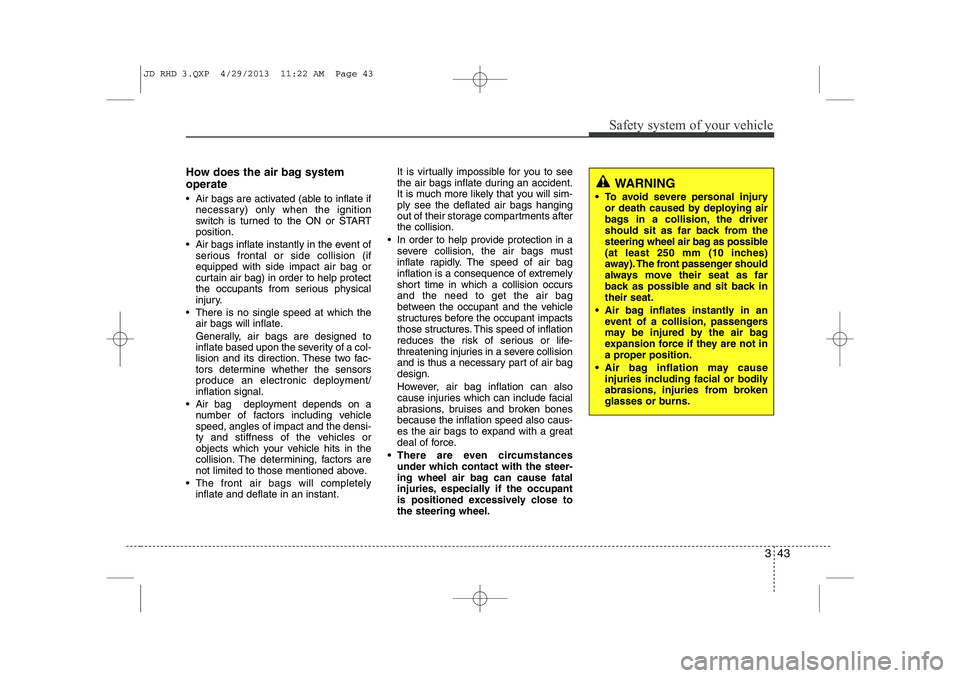
How does the air bag system operate
Air bags are activated (able to inflate ifnecessary) only when the ignition
switch is turned to the ON or STARTposition.
Air bags inflate instantly in the event of serious frontal or side collision (ifequipped with side impact air bag or
curtain air bag) in order to help protect
the occupants from serious physical
injury.
There is no single speed at which the air bags will inflate.
Generally, air bags are designed to
inflate based upon the severity of a col-
lision and its direction. These two fac-
tors determine whether the sensors
produce an electronic deployment/inflation signal.
Air bag deployment depends on a number of factors including vehiclespeed, angles of impact and the densi-
ty and stiffness of the vehicles or
objects which your vehicle hits in the
collision. The determining, factors are
not limited to those mentioned above.
The front air bags will completely inflate and deflate in an instant. It is virtually impossible for you to see
the air bags inflate during an accident.
It is much more likely that you will sim-ply see the deflated air bags hanging
out of their storage compartments afterthe collision.
In order to help provide protection in a severe collision, the air bags must
inflate rapidly. The speed of air bag
inflation is a consequence of extremely
short time in which a collision occursand the need to get the air bag
between the occupant and the vehicle
structures before the occupant impacts
those structures. This speed of inflation
reduces the risk of serious or life-
threatening injuries in a severe collision
and is thus a necessary part of air bagdesign.
However, air bag inflation can also
cause injuries which can include facial
abrasions, bruises and broken bonesbecause the inflation speed also caus-
es the air bags to expand with a great
deal of force.
There are even circumstances under which contact with the steer-
ing wheel air bag can cause fatal
injuries, especially if the occupant
is positioned excessively close tothe steering wheel.
WARNING
To avoid severe personal injury or death caused by deploying air
bags in a collision, the driver
should sit as far back from the
steering wheel air bag as possible
(at least 250 mm (10 inches)
away). The front passenger should
always move their seat as far
back as possible and sit back intheir seat.
Air bag inflates instantly in an event of a collision, passengers
may be injured by the air bag
expansion force if they are not in
a proper position.
Air bag inflation may cause injuries including facial or bodily
abrasions, injuries from broken
glasses or burns.
JD RHD 3.QXP 4/29/2013 11:22 AM Page 43
Page 730 of 1206
Features of your vehicle
46
4
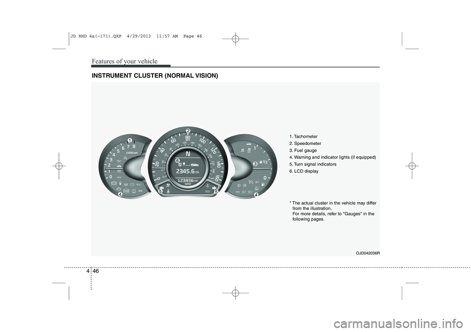
INSTRUMENT CLUSTER (NORMAL VISION)
1. Tachometer
2. Speedometer
3. Fuel gauge
4. Warning and indicator lights (if equipped)
5. Turn signal indicators
6. LCD display
OJD042036R
* The actual cluster in the vehicle may differ
from the illustration.
For more details, refer to "Gauges" in the
following pages.
JD RHD 4a(~171).QXP 4/29/2013 11:57 AM Page 46
Page 743 of 1206
459
Features of your vehicle
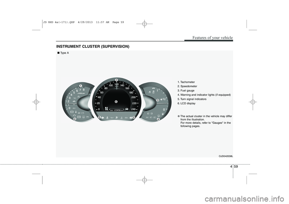
INSTRUMENT CLUSTER (SUPERVISION)
1. Tachometer
2. Speedometer
3. Fuel gauge
4. Warning and indicator lights (if equipped)
5. Turn signal indicators
6. LCD displayOJD042038L
❈
The actual cluster in the vehicle may differ
from the illustration.
For more details, refer to "Gauges" in the
following pages.
■ Type A
JD RHD 4a(~171).QXP 4/29/2013 11:57 AM Page 59
Page 744 of 1206

Features of your vehicle
60
4
1. Tachometer
2. Speedometer
3. Fuel gauge
4. Warning and indicator lights (if equipped)
5. Turn signal indicators
6. LCD display
7. Engine torque gauge
8. Turbo boost pressure gauge
9. Engine coolant temperature gauge
OJD043038/OJD043248
❈
The actual cluster in the vehicle may differ
from the illustration.
For more details, refer to "Gauges" in the
following pages.
■ Type B (for T-GDI engine)
Analog Mode Digital Mode
JD RHD 4a(~171).QXP 4/29/2013 11:58 AM Page 60
Page 765 of 1206
481
Features of your vehicle
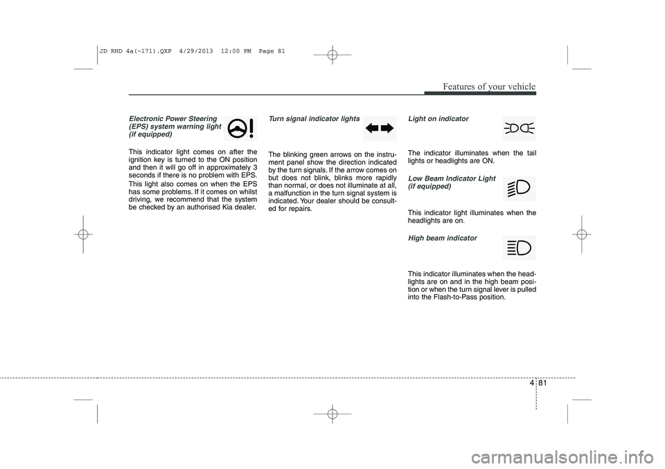
Electronic Power Steering(EPS) system warning light(if equipped)
This indicator light comes on after the
ignition key is turned to the ON position
and then it will go off in approximately 3
seconds if there is no problem with EPS. This light also comes on when the EPS
has some problems. If it comes on whilst
driving, we recommend that the system
be checked by an authorised Kia dealer.
Turn signal indicator lights
The blinking green arrows on the instru-
ment panel show the direction indicated
by the turn signals. If the arrow comes on
but does not blink, blinks more rapidly
than normal, or does not illuminate at all,
a malfunction in the turn signal system is
indicated. Your dealer should be consult-
ed for repairs.
Light on indicator
The indicator illuminates when the tail lights or headlights are ON.
Low Beam Indicator Light
(if equipped)
This indicator light illuminates when the headlights are on.
High beam indicator
This indicator illuminates when the head- lights are on and in the high beam posi-
tion or when the turn signal lever is pulled
into the Flash-to-Pass position.
JD RHD 4a(~171).QXP 4/29/2013 12:00 PM Page 81
Page 794 of 1206
Features of your vehicle
110
4
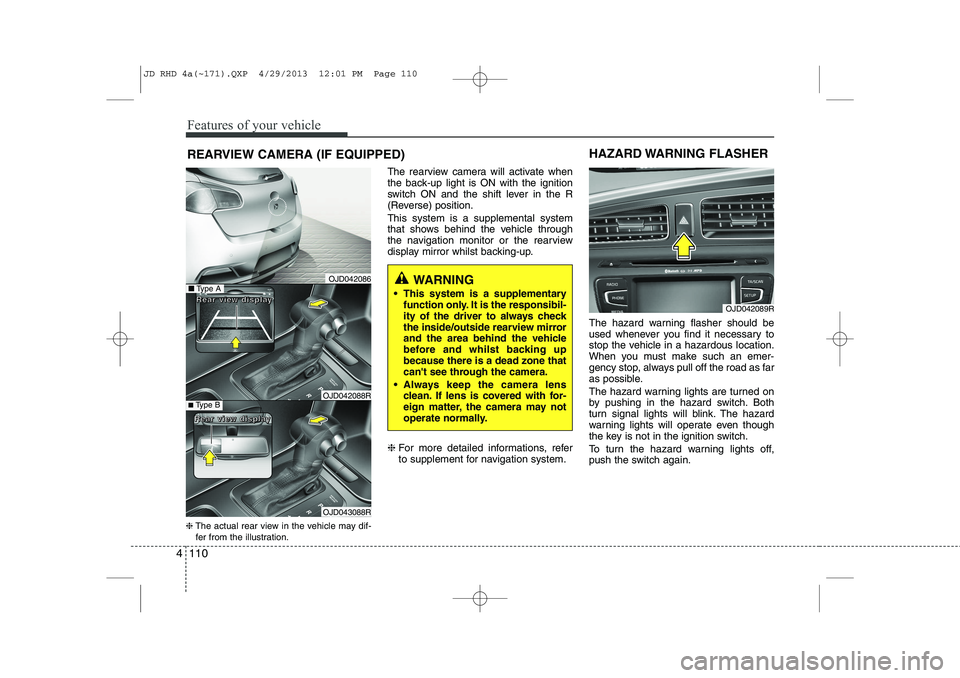
REARVIEW CAMERA (IF EQUIPPED)
❈ The actual rear view in the vehicle may dif-
fer from the illustration. The rearview camera will activate when
the back-up light is ON with the ignition
switch ON and the shift lever in the R
(Reverse) position. This system is a supplemental system
that shows behind the vehicle through
the navigation monitor or the rearview
display mirror whilst backing-up. ❈
For more detailed informations, refer
to supplement for navigation system. The hazard warning flasher should be
used whenever you find it necessary to
stop the vehicle in a hazardous location.
When you must make such an emer-
gency stop, always pull off the road as far
as possible.
The hazard warning lights are turned on
by pushing in the hazard switch. Both
turn signal lights will blink. The hazard
warning lights will operate even though
the key is not in the ignition switch.
To turn the hazard warning lights off,
push the switch again.
OJD042089R
HAZARD WARNING FLASHER
WARNING
This system is a supplementary function only. It is the responsibil-
ity of the driver to always check
the inside/outside rearview mirror
and the area behind the vehicle
before and whilst backing upbecause there is a dead zone that
can't see through the camera.
Always keep the camera lens clean. If lens is covered with for-
eign matter, the camera may not
operate normally.■Type A
■Type B
RRRReeeeaaaarrrr vvvviiiieeeewwww ddddiiiissssppppllllaaaayyyy
RRRReeeeaaaarrrr vvvviiiieeeewwww ddddiiiissssppppllllaaaayyyy
OJD042086
OJD042088R
OJD043088R
JD RHD 4a(~171).QXP 4/29/2013 12:01 PM Page 110
Page 799 of 1206
4 115
Features of your vehicle
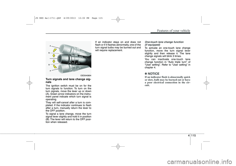
Turn signals and lane change sig- nals
The ignition switch must be on for the
turn signals to function. To turn on the
turn signals, move the lever up or down
(A). Green arrow indicators on the instru-
ment panel indicate which turn signal is
operating.
They will self-cancel after a turn is com-
pleted. If the indicator continues to flash
after a turn, manually return the lever tothe OFF position.
To signal a lane change, move the turn
signal lever slightly and hold it in position
(B). The lever will return to the OFF posi-tion when released.If an indicator stays on and does not
flash or if it flashes abnormally, one of the
turn signal bulbs may be burned out andwill require replacement.
One-touch lane change function
(if equipped)
To activate an one-touch lane change
function, move the turn signal lever
slightly and then release it. The lane
change signals will blink 3 times.
You can inactivate one-touch lane
change function in “Auto triple turn” of
“User setting”. Refer to “User setting” inchapter 4.
✽✽ NOTICE
If an indicator flash is abnormally quick
or slow, bulb may be burned out or have
a poor electrical connection in the cir-cuit.OED040804
JD RHD 4a(~171).QXP 4/29/2013 12:02 PM Page 115
Page 1010 of 1206
561
Driving your vehicle
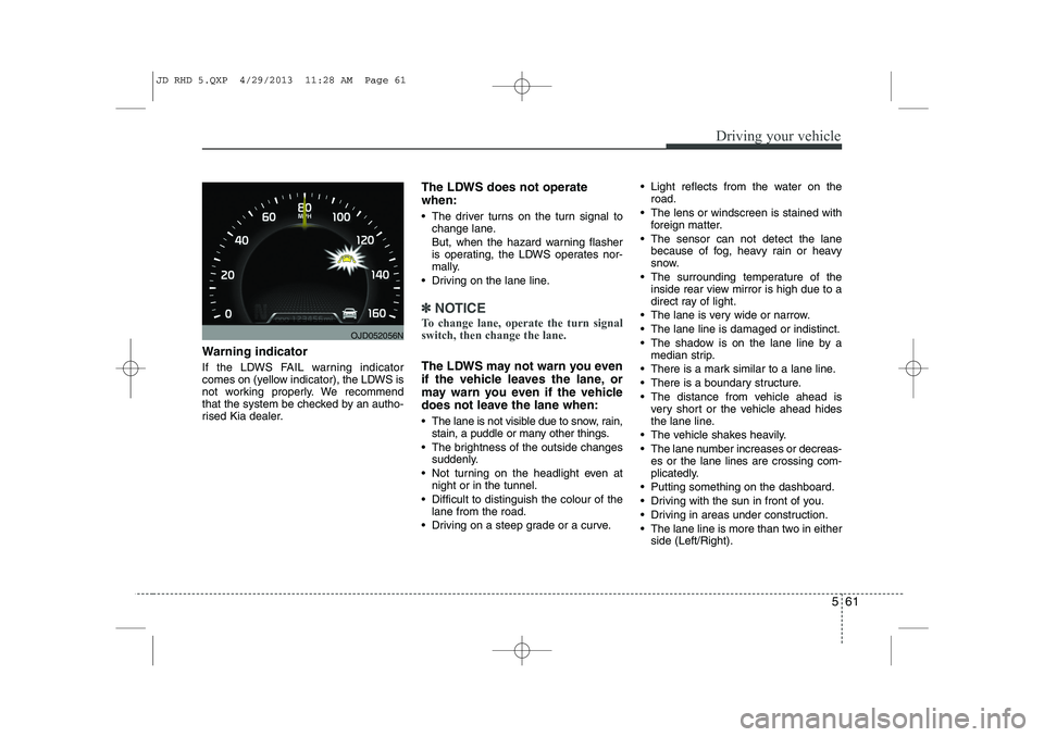
Warning indicator
If the LDWS FAIL warning indicator
comes on (yellow indicator), the LDWS is
not working properly. We recommend
that the system be checked by an autho-
rised Kia dealer.The LDWS does not operate when:
The driver turns on the turn signal to
change lane.
But, when the hazard warning flasher
is operating, the LDWS operates nor-
mally.
Driving on the lane line.
✽✽ NOTICE
To change lane, operate the turn signal switch, then change the lane.
The LDWS may not warn you even
if the vehicle leaves the lane, or
may warn you even if the vehicle
does not leave the lane when:
The lane is not visible due to snow, rain, stain, a puddle or many other things.
The brightness of the outside changes suddenly.
Not turning on the headlight even at night or in the tunnel.
Difficult to distinguish the colour of the lane from the road.
Driving on a steep grade or a curve. Light reflects from the water on the
road.
The lens or windscreen is stained with foreign matter.
The sensor can not detect the lane because of fog, heavy rain or heavy
snow.
The surrounding temperature of the inside rear view mirror is high due to a
direct ray of light.
The lane is very wide or narrow.
The lane line is damaged or indistinct.
The shadow is on the lane line by a median strip.
There is a mark similar to a lane line.
There is a boundary structure.
The distance from vehicle ahead is very short or the vehicle ahead hides
the lane line.
The vehicle shakes heavily.
The lane number increases or decreas- es or the lane lines are crossing com-
plicatedly.
Putting something on the dashboard.
Driving with the sun in front of you.
Driving in areas under construction.
The lane line is more than two in either side (Left/Right).
OJD052056N
JD RHD 5.QXP 4/29/2013 11:28 AM Page 61