lock KIA Cerato 2015 2.G Owner's Manual
[x] Cancel search | Manufacturer: KIA, Model Year: 2015, Model line: Cerato, Model: KIA Cerato 2015 2.GPages: 452, PDF Size: 7.85 MB
Page 393 of 452
739
Maintenance
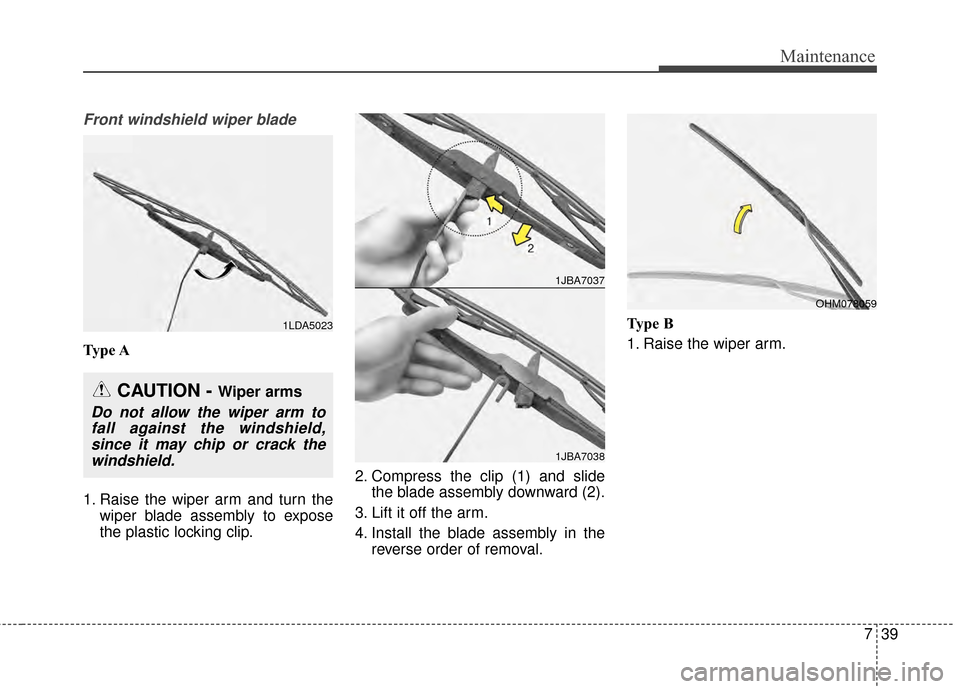
Front windshield wiper blade
Type A
1. Raise the wiper arm and turn thewiper blade assembly to expose
the plastic locking clip. 2. Compress the clip (1) and slide
the blade assembly downward (2).
3. Lift it off the arm.
4. Install the blade assembly in the reverse order of removal. Type B
1. Raise the wiper arm.
1LDA5023
CAUTION - Wiper arms
Do not allow the wiper arm to
fall against the windshield,since it may chip or crack thewindshield.
1JBA7037
1JBA7038
OHM078059
Page 397 of 452
743
Maintenance
Battery recharging
Your vehicle has a maintenance-free,
calcium-based battery.
If the battery becomes dischargedin a short time (because, for exam-
ple, the headlights or interior lights
were left on while the vehicle was
not in use), recharge it by slow
charging (trickle) for 10 hours.
If the battery gradually discharges because of high electric load while
the vehicle is being used, recharge
it at 20-30A for two hours. When recharging the battery,
observe the following precautions:
The battery must be removed from
the vehicle and placed in an area
with good ventilation.
Watch the battery during charging, and stop or reduce the charging
rate if the battery cells begin
gassing (boiling) violently or if the
temperature of the electrolyte of
any cell exceeds 49°C (120°F).
Wear eye protection when check- ing the battery during charging.
Disconnect the battery charger in the following order.
1. Turn off the battery charger main switch.
2. Unhook the negative clamp from the negative battery terminal.
3. Unhook the positive clamp from the positive battery terminal.
Before performing maintenance or recharging the battery, turn off all
accessories and stop the engine.
The negative battery cable must be removed first and installed last
when the battery is disconnected.
Reset items
Items should be reset after the bat-
tery has been discharged or the bat-
tery has been disconnected.
Auto down window (See chapter 4)
Sunroof (See chapter 4)
Trip computer (See chapter 4)
Climate control system (See chapter 4)
Clock (See chapter 4)
Audio (See chapter 4)
Page 402 of 452
Maintenance
48
7
Tire replacement
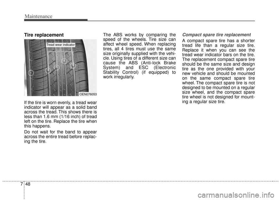
If the tire is worn evenly, a tread wear
indicator will appear as a solid band
across the tread. This shows there is
less than 1.6 mm (1/16 inch) of tread
left on the tire. Replace the tire when
this happens.
Do not wait for the band to appear
across the entire tread before replac-
ing the tire. The ABS works by comparing the
speed of the wheels. Tire size can
affect wheel speed. When replacing
tires, all 4 tires must use the same
size originally supplied with the vehi-
cle. Using tires of a different size can
cause the ABS (Anti-lock Brake
System) and ESC (Electronic
Stability Control) (if equipped) to
work irregularly.
Compact spare tire replacement
A compact spare tire has a shorter
tread life than a regular size tire.
Replace it when you can see the
tread wear indicator bars on the tire.
The replacement compact spare tire
should be the same size and design
tire as the one provided with your
new vehicle and should be mounted
on the same compact spare tire
wheel. The compact spare tire is not
designed to be mounted on a regular
size wheel, and the compact spare
tire wheel is not designed for mount-
ing a regular size tire.
OEN076053
Tread wear indicator
Page 414 of 452
Maintenance
60
7
If the headlights or other electrical
components do not work and the
fuses are OK, check the fuse panel
in the engine compartment. If a fuse
is blown, it must be replaced.Fuse switch
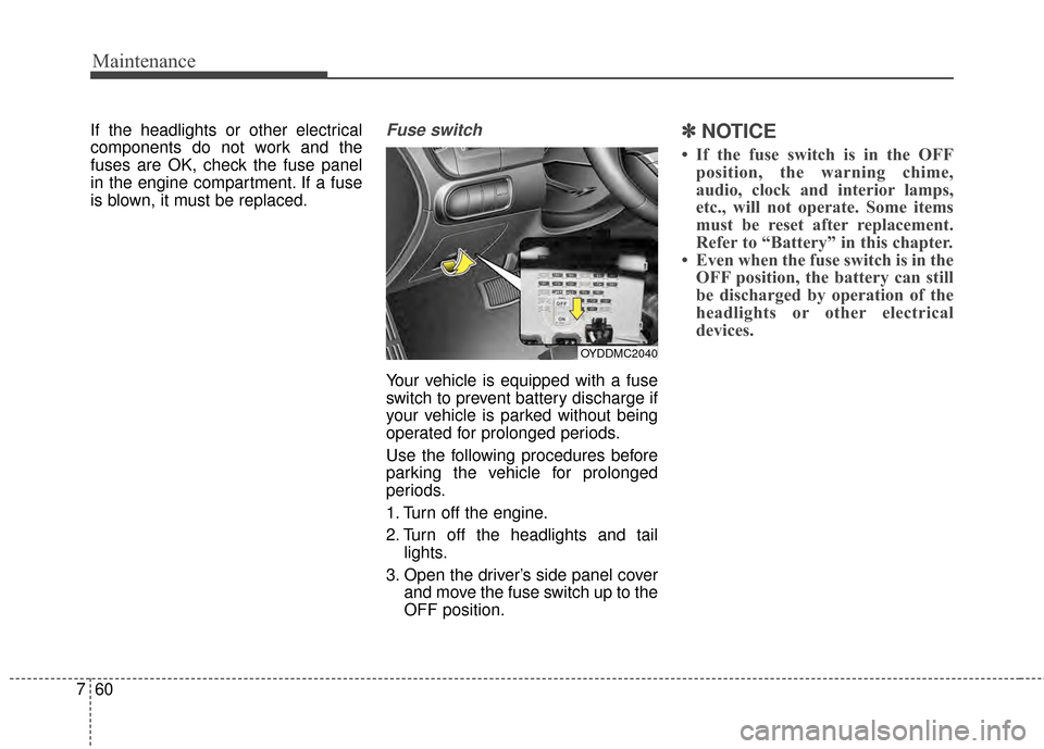
Your vehicle is equipped with a fuse
switch to prevent battery discharge if
your vehicle is parked without being
operated for prolonged periods.
Use the following procedures before
parking the vehicle for prolonged
periods.
1. Turn off the engine.
2. Turn off the headlights and tail
lights.
3. Open the driver’s side panel cover and move the fuse switch up to the
OFF position.
✽ ✽NOTICE
• If the fuse switch is in the OFF
position, the warning chime,
audio, clock and interior lamps,
etc., will not operate. Some items
must be reset after replacement.
Refer to “Battery” in this chapter.
• Even when the fuse switch is in the OFF position, the battery can still
be discharged by operation of the
headlights or other electrical
devices.
OYDDMC2040
Page 420 of 452
Maintenance
66
7
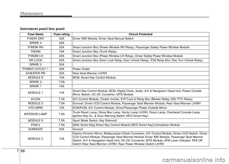
Instrument panel fuse panel
Fuse Name Fuse rating Circuit Protected
P/SEAT DRV 30A Driver IMS Module, Driver Seat Manual Switch SPARE 4 25A -
P/WDW RH 25A Smart Junction Box (Power Window RH Relay), Passenger Safety Power Window Module
TRUNK 10A Smart Junction Box (Trunk Relay)
P/WDW LH 25A Smart Junction Box (Power Window LH Relay), Driver Safety Power Window Module
DR LOCK 20A Smart Junction Box (Door Lock Relay, Door Unlock Relay), ICM Relay Box (Two Turn Unlock Relay)
SPARE 3 20A -
POWER OUTLET 1 20A Power Outlet S/HEATER RR 20A Rear Seat Warmer LH/RH MODULE 8 10A BCM, Smart Key Control Module
SPARE 2 7.5A -
SPARE 1 15A -
MODULE 1 10A Smart Key Control Module, BCM, Digital Clock, Audio, A/V & Navigation Head Unit, Power Outside
Mirror Switch, DC-DC Converter, MTS Module
A/CON 7.5A A/C Control Module, Cluster Ionizer, E/R Fuse & Relay Box (Blower Relay, GSL PTC Relay)
MODULE 5 7.5A Sunroof, Driver CCS Control Module, Passenger Seat Warmer Module, Rear Seat Warmer LH/RH HTD MIRR 10A ECM/PCM, A/C Control Module, Driver/Passenger Power Outside Mirror
INTERIOR LAMP 7.5A Trunk Room Lamp, Glove Box Lamp, Vanity Lamp LH/RH, Room Lamp, Overhead Console Lamp,
Ignition Key ILL. & Door Warning Switch (W/O Smart Key)
MODULE 6 7.5A Sport Mode Switch, Key Solenoid PDM 2 7.5A [With Smart Key] Smart Key Control Module [W/O Smart Key] Immobilizer Module
SUNROOF 20A Sunroof
MODULE 2 10A
Electro Chromic Mirror, Multipurpose Check Connector, A/C Control Module, Driver CCS Switch, Driver
CCS Control Module, Passenger Seat Warmer Module Driver IMS Module, Passenger Seat Warmer
Switch, A/V & Navigation Head Unit, DC-DC Converter, MTS Module, ATM Lever Indicator, PAS Off
Switch Rear Seat Warmer LH/RH, Rear Power Window Switch LH/RH
Page 421 of 452
767
Maintenance
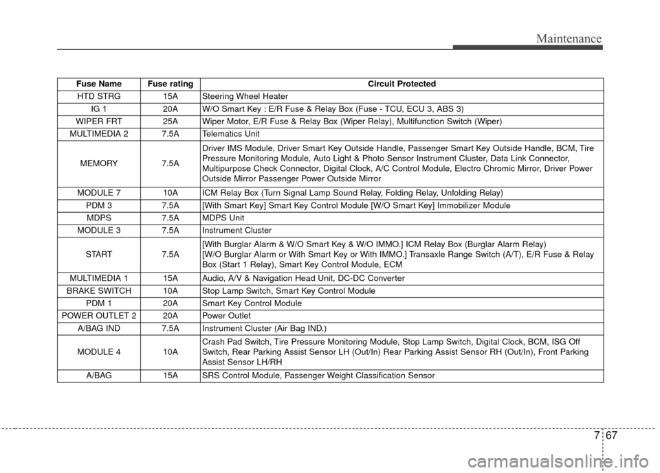
Fuse Name Fuse ratingCircuit Protected
HTD STRG 15A Steering Wheel Heater IG 1 20A W/O Smart Key : E/R Fuse & Relay Box (Fuse - TCU, ECU 3, ABS 3)
WIPER FRT 25A Wiper Motor, E/R Fuse & Relay Box (Wiper Relay), Multifunction Switch (Wiper)
MULTIMEDIA 2 7.5A Telematics Unit
MEMORY 7.5ADriver IMS Module, Driver Smart Key Outside Handle, Passenger Smart Key Outside Handle, BCM, Tire
Pressure Monitoring Module, Auto Light & Photo Sensor Instrument Cluster, Data Link Connector,
Multipurpose Check Connector, Digital Clock, A/C Control Module, Electro Chromic Mirror, Driver Power
Outside Mirror Passenger Power Outside Mirror
MODULE 7 10A ICM Relay Box (Turn Signal Lamp Sound Relay, Folding Relay, Unfolding Relay) PDM 3 7.5A [With Smart Key] Smart Key Control Module [W/O Smart Key] Immobilizer Module
MDPS 7.5A MDPS Unit
MODULE 3 7.5A Instrument Cluster
START 7.5A[With Burglar Alarm & W/O Smart Key & W/O IMMO.] ICM Relay Box (Burglar Alarm Relay)
[W/O Burglar Alarm or With Smart Key or With IMMO.] Transaxle Range Switch (A/T), E/R Fuse & Relay
Box (Start 1 Relay), Smart Key Control Module, ECM
MULTIMEDIA 1 15A Audio, A/V & Navigation Head Unit, DC-DC Converter
BRAKE SWITCH 10A Stop Lamp Switch, Smart Key Control Module PDM 1 20A Smart Key Control Module
POWER OUTLET 2 20A Power Outlet A/BAG IND 7.5A Instrument Cluster (Air Bag IND.)
MODULE 4 10A Crash Pad Switch, Tire Pressure Monitoring Module, Stop Lamp Switch, Digital Clock, BCM, ISG Off
Switch, Rear Parking Assist Sensor LH (Out/In) Rear Parking Assist Sensor RH (Out/In), Front Parking
Assist Sensor LH/RH
A/BAG 15A SRS Control Module, Passenger Weight Classification Sensor
Page 422 of 452
Maintenance
68
7
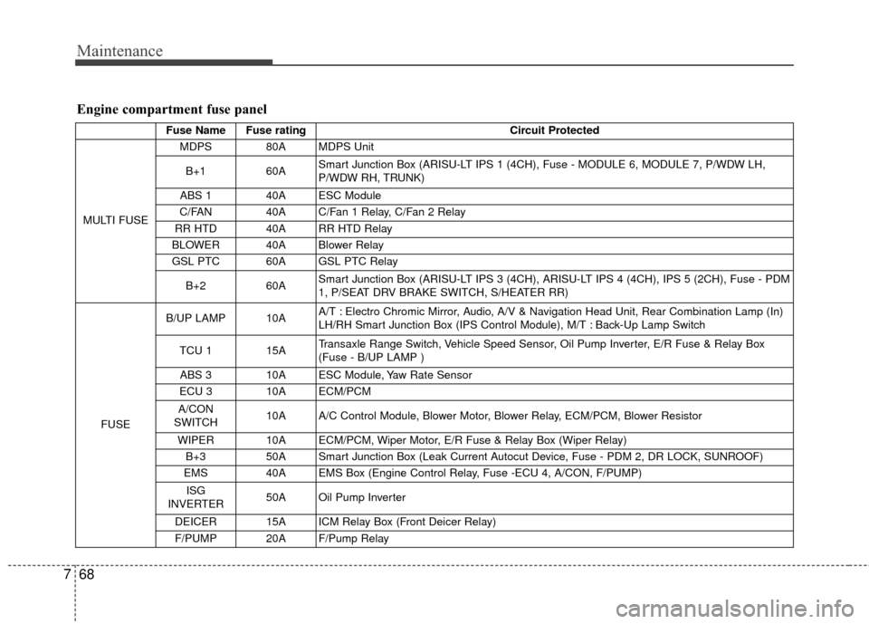
Engine compartment fuse panel
Fuse Name Fuse rating Circuit Protected
MULTI FUSE MDPS 80A MDPS Unit
B+1 60A Smart Junction Box (ARISU-LT IPS 1 (4CH), Fuse - MODULE 6, MODULE 7, P/WDW LH,
P/WDW RH, TRUNK)
ABS 1 40A ESC Module
C/FAN 40A C/Fan 1 Relay, C/Fan 2 Relay
RR HTD 40A RR HTD Relay
BLOWER 40A Blower Relay
GSL PTC 60A GSL PTC Relay
B+2 60A Smart Junction Box (ARISU-LT IPS 3 (4CH), ARISU-LT IPS 4 (4CH), IPS 5 (2CH), Fuse - PDM
1, P/SEAT DRV BRAKE SWITCH, S/HEATER RR)
FUSE B/UP LAMP 10A
A/T : Electro Chromic Mirror, Audio, A/V & Navigation Head Unit, Rear Combination Lamp (In)
LH/RH Smart Junction Box (IPS Control Module), M/T : Back-Up Lamp Switch
TCU 1 15A Transaxle Range Switch, Vehicle Speed Sensor, Oil Pump Inverter, E/R Fuse & Relay Box
(Fuse - B/UP LAMP )
ABS 3 10A ESC Module, Yaw Rate Sensor
ECU 3 10A ECM/PCM
A/CON
SWITCH 10A A/C Control Module, Blower Motor, Blower Relay, ECM/PCM, Blower Resistor
WIPER 10A ECM/PCM, Wiper Motor, E/R Fuse & Relay Box (Wiper Relay) B+3 50A Smart Junction Box (Leak Current Autocut Device, Fuse - PDM 2, DR LOCK, SUNROOF)
EMS 40A EMS Box (Engine Control Relay, Fuse -ECU 4, A/CON, F/PUMP)
ISG
INVERTER 50A Oil Pump Inverter
DEICER 15A ICM Relay Box (Front Deicer Relay)
F/PUMP 20A F/Pump Relay
Page 444 of 452
Specifications & Consumer information
10
8
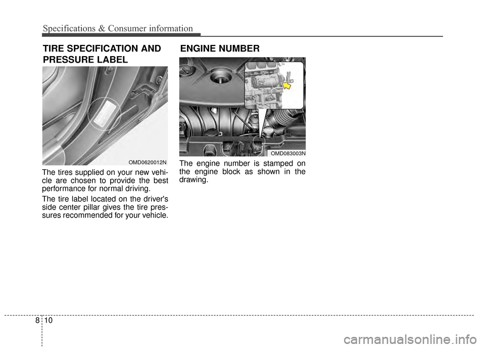
The tires supplied on your new vehi-
cle are chosen to provide the best
performance for normal driving.
The tire label located on the driver's
side center pillar gives the tire pres-
sures recommended for your vehicle. The engine number is stamped on
the engine block as shown in the
drawing.
TIRE SPECIFICATION AND
PRESSURE LABEL
OMD0620012N
ENGINE NUMBER
OMD083003N
Page 446 of 452
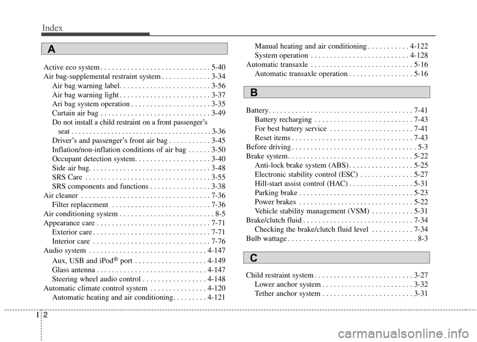
Index
2I
Active eco system . . . . . . . . . . . . . . . . . . . . . . . . . . . . . 5-40
Air bag-supplemental restraint system . . . . . . . . . . . . . 3-34Air bag warning label. . . . . . . . . . . . . . . . . . . . . . . . 3-56
Air bag warning light . . . . . . . . . . . . . . . . . . . . . . . . 3-37
Ari bag system operation . . . . . . . . . . . . . . . . . . . . . 3-35
Curtain air bag . . . . . . . . . . . . . . . . . . . . . . . . . . . . . 3-49
Do not install a child restraint on a front passenger’sseat . . . . . . . . . . . . . . . . . . . . . . . . . . . . . . . . . . . . \
. . . 3-36
Driver’s and passenger’s front air bag . . . . . . . . . . . 3-45
Inflation/non-inflation conditions of air bag . . . . . . 3-50
Occupant detection system. . . . . . . . . . . . . . . . . . . . 3-40
Side air bag. . . . . . . . . . . . . . . . . . . . . . . . . . . . . . . . 3-48
SRS Care . . . . . . . . . . . . . . . . . . . . . . . . . . . . . . . . . 3-55
SRS components and functions . . . . . . . . . . . . . . . . 3-38
Air cleaner . . . . . . . . . . . . . . . . . . . . . . . . . . . . . . . . . . 7-36\
Filter replacement . . . . . . . . . . . . . . . . . . . . . . . . . . 7-36
Air conditioning system . . . . . . . . . . . . . . . . . . . . . . . . . 8-5
Appearance care . . . . . . . . . . . . . . . . . . . . . . . . . . . . . . 7-71 Exterior care . . . . . . . . . . . . . . . . . . . . . . . . . . . . . . . 7-71
Interior care . . . . . . . . . . . . . . . . . . . . . . . . . . . . . . . 7-76
Audio system . . . . . . . . . . . . . . . . . . . . . . . . . . . . . . . 4-147
Aux, USB and iPod
®port . . . . . . . . . . . . . . . . . . . 4-149
Glass antenna . . . . . . . . . . . . . . . . . . . . . . . . . . . . . 4-147
Steering wheel audio control . . . . . . . . . . . . . . . . . 4-148
Automatic climate control system . . . . . . . . . . . . . . . 4-120 Automatic heating and air conditioning. . . . . . . . . 4-121 Manual heating and air conditioning . . . . . . . . . . . 4-122
System operation . . . . . . . . . . . . . . . . . . . . . . . . . . 4-128
Automatic transaxle . . . . . . . . . . . . . . . . . . . . . . . . . . . 5-16 Automatic transaxle operation . . . . . . . . . . . . . . . . . 5-16
Battery. . . . . . . . . . . . . . . . . . . . . . . . . . . . . . . . . . . . \
. . 7-41 Battery recharging . . . . . . . . . . . . . . . . . . . . . . . . . . 7-43
For best battery service . . . . . . . . . . . . . . . . . . . . . . 7-41
Reset items . . . . . . . . . . . . . . . . . . . . . . . . . . . . . . . . 7-43
Before driving . . . . . . . . . . . . . . . . . . . . . . . . . . . . . . . . . 5-3
Brake system. . . . . . . . . . . . . . . . . . . . . . . . . . . . . . . . . 5-22 Anti-lock brake system (ABS) . . . . . . . . . . . . . . . . . 5-25
Electronic stability control (ESC) . . . . . . . . . . . . . . 5-27
Hill-start assist control (HAC) . . . . . . . . . . . . . . . . . 5-31
Parking brake . . . . . . . . . . . . . . . . . . . . . . . . . . . . . . 5-23
Power brakes . . . . . . . . . . . . . . . . . . . . . . . . . . . . . . 5-22
Vehicle stability management (VSM) . . . . . . . . . . . 5-31
Brake/clutch fluid . . . . . . . . . . . . . . . . . . . . . . . . . . . . . 7-34 Checking the brake/clutch fluid level . . . . . . . . . . . 7-34
Bulb wattage . . . . . . . . . . . . . . . . . . . . . . . . . . . . . . . . . . 8-3
Child restraint system . . . . . . . . . . . . . . . . . . . . . . . . . . 3-27 Lower anchor system . . . . . . . . . . . . . . . . . . . . . . . . 3-32
Tether anchor system . . . . . . . . . . . . . . . . . . . . . . . . 3-31
A
B
C
Page 447 of 452

I3
Index
Using a child restraint system . . . . . . . . . . . . . . . . . 3-28
Climate control air filter . . . . . . . . . . . . . . . . . . . . . . . . 7-37 Filter inspection . . . . . . . . . . . . . . . . . . . . . . . . . . . . 7-37
Cruise control system . . . . . . . . . . . . . . . . . . . . . . . . . . 5-35
Defroster . . . . . . . . . . . . . . . . . . . . . . . . . . . . . . . . . . . 4-\
109 Front wiper deicer . . . . . . . . . . . . . . . . . . . . . . . . . 4-109
Rear window defroster . . . . . . . . . . . . . . . . . . . . . . 4-109
Dimensions . . . . . . . . . . . . . . . . . . . . . . . . . . . . . . . . . . . 8-\
2
Door locks. . . . . . . . . . . . . . . . . . . . . . . . . . . . . . . . . . . 4-\
18 Auto door lock/unlock feature . . . . . . . . . . . . . . . . . 4-20
Child-protector rear door lock . . . . . . . . . . . . . . . . . 4-21
From inside. . . . . . . . . . . . . . . . . . . . . . . . . . . . . . . . 4-18
From outside. . . . . . . . . . . . . . . . . . . . . . . . . . . . . . . 4-18
Impact sensing door unlock system . . . . . . . . . . . . . 4-20
Speed sensing door lock system . . . . . . . . . . . . . . . 4-21
Economical operation . . . . . . . . . . . . . . . . . . . . . . . . . . 5-41
Emergency starting . . . . . . . . . . . . . . . . . . . . . . . . . . . . . 6-5 If the engine overheats . . . . . . . . . . . . . . . . . . . . . . . . 6-7
Jump starting . . . . . . . . . . . . . . . . . . . . . . . . . . . . . . . 6-5
Push-starting . . . . . . . . . . . . . . . . . . . . . . . . . . . . . . . . 6-6
Emission control system . . . . . . . . . . . . . . . . . . . . . . . . 7-78 Crankcase emission control system . . . . . . . . . . . . . 7-78 Evaporative emission control
(including ORVR: Onboard Refueling Vapor
Recovery) system . . . . . . . . . . . . . . . . . . . . . . . . . 7-78
Exhaust emission control system . . . . . . . . . . . . . . . 7-79
Engine . . . . . . . . . . . . . . . . . . . . . . . . . . . . . . . . . . . . \
. . . 8-2
Engine compartment . . . . . . . . . . . . . . . . . . . . . . . . 2-6, 7-3
Engine coolant . . . . . . . . . . . . . . . . . . . . . . . . . . . . . . . 7-31 Changing the coolant . . . . . . . . . . . . . . . . . . . . . . . . 7-33
Checking the coolant level . . . . . . . . . . . . . . . . . . . . 7-31
Engine number . . . . . . . . . . . . . . . . . . . . . . . . . . . . . . . 8-10
Engine oil . . . . . . . . . . . . . . . . . . . . . . . . . . . . . . . . . . . 7-\
29 Changing the engine oil and filter . . . . . . . . . . . . . . 7-30
Checking the engine oil level . . . . . . . . . . . . . . . . . 7-29
Engine start/stop button . . . . . . . . . . . . . . . . . . . . . . . . . 5-7 ENGINE START/STOP button position . . . . . . . . . . 5-7
Illuminated ENGINE START/STOP button . . . . . . . 5-7
Explanation of scheduled maintenance items . . . . . . . 7-25
Exterior overview . . . . . . . . . . . . . . . . . . . . . . . . . . . . . . 2-2
Fuel filler lid . . . . . . . . . . . . . . . . . . . . . . . . . . . . . . . . . 4-34 Closing the fuel filler lid . . . . . . . . . . . . . . . . . . . . . 4-34
Opening the fuel filler lid. . . . . . . . . . . . . . . . . . . . . 4-34
Fuel requirements . . . . . . . . . . . . . . . . . . . . . . . . . . . . . . 1-3 Do not use methanol . . . . . . . . . . . . . . . . . . . . . . . . . 1-4
Fuel Additives . . . . . . . . . . . . . . . . . . . . . . . . . . . . . . 1-5
Gasoline containing alcohol and methanol . . . . . . . . 1-3
D
EF