light KIA Magnetis 2006 2.G Manual PDF
[x] Cancel search | Manufacturer: KIA, Model Year: 2006, Model line: Magnetis, Model: KIA Magnetis 2006 2.GPages: 225, PDF Size: 3.77 MB
Page 177 of 225
MAINTENANCE
7-1
MAINTENANCEMaintenance Services . . . . . . . . . . . . . . . . . . . . . . . . . . .7-2
Maintenance Schedule . . . . . . . . . . . . . . . . . . . . . . . . . .7-3
Owner Maintenance . . . . . . . . . . . . . . . . . . . . . . . . . . . . .7-8
Engine Compartment . . . . . . . . . . . . . . . . . . . . . . . . . .7-10
Engine Oil and Oil Filter . . . . . . . . . . . . . . . . . . . . . . . .7-12
Engine Cooling System . . . . . . . . . . . . . . . . . . . . . . . . .7-14
Brakes and Clutch . . . . . . . . . . . . . . . . . . . . . . . . . . . . .7-17
Parking Brake . . . . . . . . . . . . . . . . . . . . . . . . . . . . . . . . .7-18
Power Steering . . . . . . . . . . . . . . . . . . . . . . . . . . . . . . . .7-18
Automatic Transaxle . . . . . . . . . . . . . . . . . . . . . . . . . . .7-19
Lubricants and Fluids . . . . . . . . . . . . . . . . . . . . . . . . . .7-20
Air Cleaner . . . . . . . . . . . . . . . . . . . . . . . . . . . . . . . . . . .7-21
Wiper Blades . . . . . . . . . . . . . . . . . . . . . . . . . . . . . . . . .7-22
Battery . . . . . . . . . . . . . . . . . . . . . . . . . . . . . . . . . . . . . .7-23
Tires and Wheels . . . . . . . . . . . . . . . . . . . . . . . . . . . . . .7-25
Bulb Replacement . . . . . . . . . . . . . . . . . . . . . . . . . . . . .7-32
Lubricant Specifications . . . . . . . . . . . . . . . . . . . . . . . .7-36
Exterior Care . . . . . . . . . . . . . . . . . . . . . . . . . . . . . . . . .7-38
Interior Care . . . . . . . . . . . . . . . . . . . . . . . . . . . . . . . . . .7-40
Headlight Aiming Adjustment . . . . . . . . . . . . . . . . . . .7-42
7
MS-CNA-Eng 7.QXD 7/25/2005 5:09 PM Page 1
Page 199 of 225
7-23
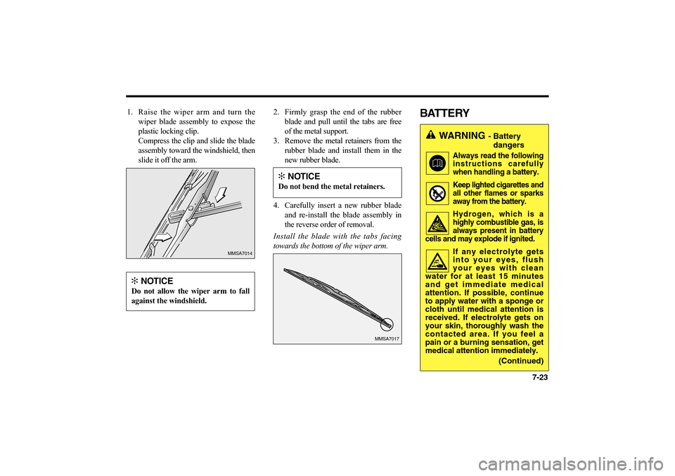
1. Raise the wiper arm and turn the
wiper blade assembly to expose the
plastic locking clip.
Compress the clip and slide the blade
assembly toward the windshield, then
slide it off the arm.2. Firmly grasp the end of the rubber
blade and pull until the tabs are free
of the metal support.
3. Remove the metal retainers from the
rubber blade and install them in the
new rubber blade.
4. Carefully insert a new rubber blade
and re-install the blade assembly in
the reverse order of removal.
Install the blade with the tabs facing
towards the bottom of the wiper arm.
BATTERY
MMSA7014
MMSA7017
✻
NOTICE
Do not allow the wiper arm to fall
against the windshield.
✻
NOTICE
Do not bend the metal retainers.
WARNING
- Battery
dangers
Always read the following
instructions carefully
when handling a battery.Keep lighted cigarettes and
all other flames or sparks
away from the battery.Hydrogen, which is a
highly combustible gas, is
always present in battery
cells and may explode if ignited.If any electrolyte gets
into your eyes, flush
your eyes with clean
water for at least 15 minutes
and get immediate medical
attention. If possible, continue
to apply water with a sponge or
cloth until medical attention is
received. If electrolyte gets on
your skin, thoroughly wash the
contacted area. If you feel a
pain or a burning sensation, get
medical attention immediately.
(Continued)
MS-CNA-Eng 7.QXD 7/25/2005 5:09 PM Page 23
Page 200 of 225
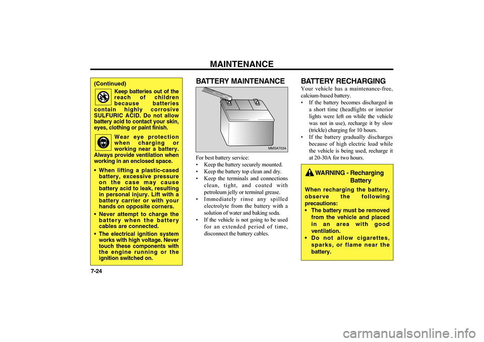
BATTERY MAINTENANCEFor best battery service:
• Keep the battery securely mounted.
• Keep the battery top clean and dry.
• Keep the terminals and connections
clean, tight, and coated with
petroleum jelly or terminal grease.
• Immediately rinse any spilled
electrolyte from the battery with a
solution of water and baking soda.
• If the vehicle is not going to be used
for an extended period of time,
disconnect the battery cables.
BATTERY RECHARGINGYour vehicle has a maintenance-free,
calcium-based battery.
• If the battery becomes discharged in
a short time (headlights or interior
lights were left on while the vehicle
was not in use), recharge it by slow
(trickle) charging for 10 hours.
• If the battery gradually discharges
because of high electric load while
the vehicle is being used, recharge it
at 20-30A for two hours.
MAINTENANCE
7-24
MMSA7034
(Continued)
Keep batteries out of the
reach of children
because batteries
contain highly corrosive
SULFURIC ACID. Do not allow
battery acid to contact your skin,
eyes, clothing or paint finish.
Wear eye protection
when charging or
working near a battery.
Always provide ventilation when
working in an enclosed space.
When lifting a plastic-cased
battery, excessive pressure
on the case may cause
battery acid to leak, resulting
in personal injury. Lift with a
battery carrier or with your
hands on opposite corners.
Never attempt to charge the
battery when the battery
cables are connected.
The electrical ignition system
works with high voltage. Never
touch these components with
the engine running or the
ignition switched on.
WARNING - Recharging
Battery
When recharging the battery,
observe the following
precautions:
The battery must be removed
from the vehicle and placed
in an area with good
ventilation.
Do not allow cigarettes,
sparks, or flame near the
battery.
MS-CNA-Eng 7.QXD 7/25/2005 5:09 PM Page 24
Page 208 of 225
MAINTENANCE
7-32WHEEL REPLACEMENTWhen replacing the metal wheels for any
reason, make sure the new wheels are
equivalent to the original factory units in
diameter, rim width and offset.
BULB REPLACEMENTHEADLIGHT BULB
REPLACEMENT
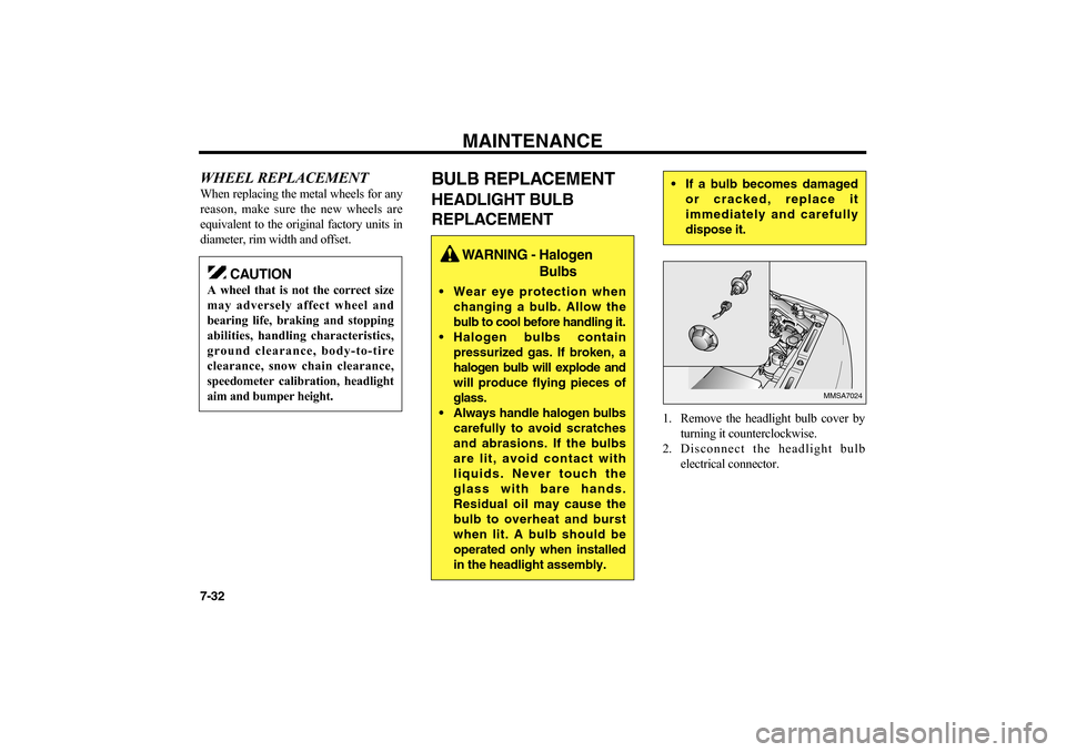
1. Remove the headlight bulb cover by
turning it counterclockwise.
2. Disconnect the headlight bulb
electrical connector.
MMSA7024
CAUTION
A wheel that is not the correct size
may adversely affect wheel and
bearing life, braking and stopping
abilities, handling characteristics,
ground clearance, body-to-tire
clearance, snow chain clearance,
speedometer calibration, headlight
aim and bumper height.
WARNING - Halogen
Bulbs
Wear eye protection when
changing a bulb. Allow the
bulb to cool before handling it.
Halogen bulbs contain
pressurized gas. If broken, a
halogen bulb will explode and
will produce flying pieces of
glass.
Always handle halogen bulbs
carefully to avoid scratches
and abrasions. If the bulbs
are lit, avoid contact with
liquids. Never touch the
glass with bare hands.
Residual oil may cause the
bulb to overheat and burst
when lit. A bulb should be
operated only when installed
in the headlight assembly.
If a bulb becomes damaged
or cracked, replace it
immediately and carefully
dispose it.
MS-CNA-Eng 7.QXD 7/25/2005 5:09 PM Page 32
Page 209 of 225
7-33
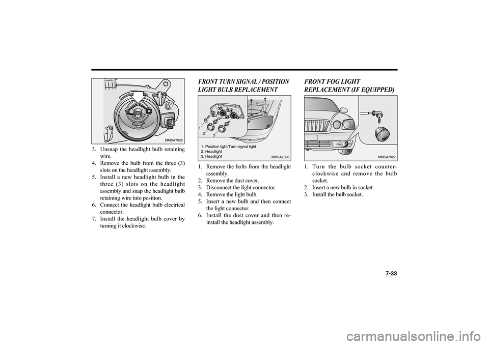
3. Unsnap the headlight bulb retaining
wire.
4. Remove the bulb from the three (3)
slots on the headlight assembly.
5. Install a new headlight bulb in the
three (3) slots on the headlight
assembly and snap the headlight bulb
retaining wire into position.
6. Connect the headlight bulb electrical
connector.
7. Install the headlight bulb cover by
turning it clockwise.
FRONT TURN SIGNAL / POSITION
LIGHT BULB REPLACEMENT1. Remove the bolts from the headlight
assembly.
2. Remove the dust cover.
3. Disconnect the light connector.
4. Remove the light bulb.
5. Insert a new bulb and then connect
the light connector.
6. Install the dust cover and then re-
install the headlight assembly.
FRONT FOG LIGHT
REPLACEMENT (IF EQUIPPED)1. Turn the bulb socket counter-
clockwise and remove the bulb
socket.
2. Insert a new bulb in socket.
3. Install the bulb socket.
MMSA7025
MMSA7026
1. Position light/Turn signal light
2. Headlight
3. Headlight
MMSA7027
1
2
3
MS-CNA-Eng 7.QXD 7/25/2005 5:09 PM Page 33
Page 210 of 225
MAINTENANCE
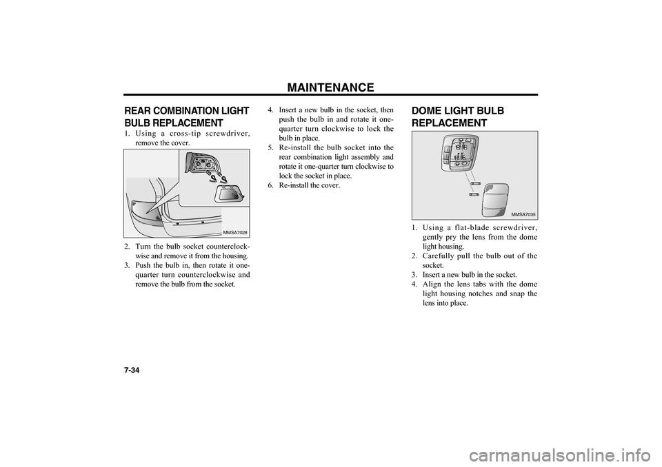
7-34REAR COMBINATION LIGHT
BULB REPLACEMENT 1. Using a cross-tip screwdriver,
remove the cover.
2. Turn the bulb socket counterclock-
wise and remove it from the housing.
3. Push the bulb in, then rotate it one-
quarter turn counterclockwise and
remove the bulb from the socket.4. Insert a new bulb in the socket, then
push the bulb in and rotate it one-
quarter turn clockwise to lock the
bulb in place.
5. Re-install the bulb socket into the
rear combination light assembly and
rotate it one-quarter turn clockwise to
lock the socket in place.
6. Re-install the cover.
DOME LIGHT BULB
REPLACEMENT1. Using a flat-blade screwdriver,
gently pry the lens from the dome
light housing.
2. Carefully pull the bulb out of the
socket.
3. Insert a new bulb in the socket.
4. Align the lens tabs with the dome
light housing notches and snap the
lens into place.
MMSA7028
O
F
FDOORON
MMSA7035
MS-CNA-Eng 7.QXD 7/25/2005 5:09 PM Page 34
Page 211 of 225
7-35
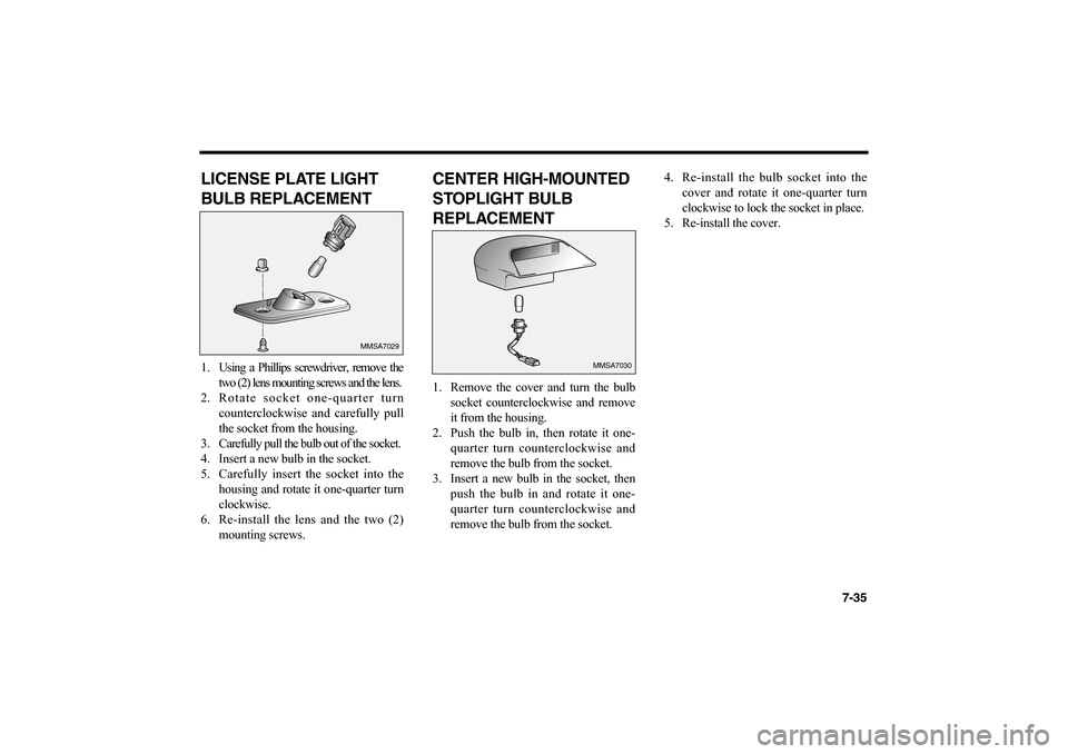
LICENSE PLATE LIGHT
BULB REPLACEMENT1. Using a Phillips screwdriver, remove the
two (2) lens mounting screws and the lens.
2. Rotate socket one-quarter turn
counterclockwise and carefully pull
the socket from the housing.
3. Carefully pull the bulb out of the socket.
4. Insert a new bulb in the socket.
5. Carefully insert the socket into the
housing and rotate it one-quarter turn
clockwise.
6. Re-install the lens and the two (2)
mounting screws.
CENTER HIGH-MOUNTED
STOPLIGHT BULB
REPLACEMENT1. Remove the cover and turn the bulb
socket counterclockwise and remove
it from the housing.
2. Push the bulb in, then rotate it one-
quarter turn counterclockwise and
remove the bulb from the socket.
3. Insert a new bulb in the socket, then
push the bulb in and rotate it one-
quarter turn counterclockwise and
remove the bulb from the socket.4. Re-install the bulb socket into the
cover and rotate it one-quarter turn
clockwise to lock the socket in place.
5. Re-install the cover.
MMSA7029
MMSA7030
MS-CNA-Eng 7.QXD 7/25/2005 5:09 PM Page 35
Page 212 of 225
MAINTENANCE
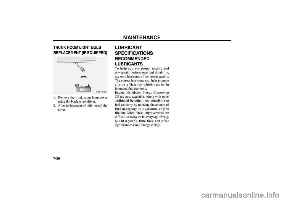
7-36TRUNK ROOM LIGHT BULB
REPLACEMENT (IF EQUIPPED)1. Remove the trunk room lamp cover
using flat blade screw driver.
2. After replacement of bulb, install the
cover.
LUBRICANT
SPECIFICATIONSRECOMMENDED
LUBRICANTSTo help achieve proper engine and
powertrain performance and durability,
use only lubricants of the proper quality.
The correct lubricants also help promote
engine efficiency which results in
improved fuel economy.
Engine oils labeled Energy Conserving
Oil are now available. Along with other
additional benefits, they contribute to
fuel economy by reducing the amount of
fuel necessary to overcome engine
friction. Often, these improvements are
difficult to measure in everyday driving,
but in a year’s time they can offer
significant cost and energy savings.
MMSA7031
MS-CNA-Eng 7.QXD 7/25/2005 5:09 PM Page 36
Page 214 of 225
MAINTENANCE
7-38When choosing an oil, consider the range
of temperature your vehicle will be
operated in before the next oil change.
Then select the recommended oil
viscosity from the chart.EXTERIOR CAREEXTERIOR GENERAL
CAUTIONIt is very important to follow the
manufacturer’s directions when using
any chemical cleaner or polish. Read all
warning and caution statements that
appear on the label.FINISH MAINTENANCE
WASHINGTo help protect your vehicle’s finish from
rust and deterioration, wash it thoroughly
and frequently at least once a month with
special attention to the removal of any
accumulation of salt, dirt, mud, or other
foreign materials. Make sure the drainholes in the lower edges of the doors and
rocker panels are kept clear and clean.
Insects, tar, tree sap, bird droppings,
industrial fallout and similar deposits can
damage your vehicle’s finish if not
removed immediately.
Even prompt washing with plain water
may not completely remove all these
deposits. A mild soap, safe for use on
painted surfaces, can be used.
After washing, rinse the vehicle
thoroughly with lukewarm or cold water.
Do not allow soap to dry on the finish.
WAXINGWax the vehicle when water will no
longer bead on the paint.
Always wash and dry the vehicle before
waxing. Use a good quality liquid or
paste wax, and follow the manufacturer’s
instructions. Wax all metal trim as well,
to protect it and to maintain its luster.
Removing oil, tar, and similar materials
with a spot remover will usually strip the
wax from the finish. Be sure to re-wax
these areas even if the rest of the vehicle
does not yet need waxing.
✻
NOTICE
Do not use strong soap, chemical
detergents or hot water, and do not
wash the vehicle in direct sunlight
or when the body of the vehicle is
warm.
CAUTION
After washing the vehicle, test the
brakes while driving slowly to see if
they have been affected by water. If
braking performance is impaired,
dry the brakes by applying them
lightly while maintaining a slow
forward speed.
MS-CNA-Eng 7.QXD 7/25/2005 5:09 PM Page 38
Page 218 of 225
MAINTENANCE
7-42HEADLIGHT AIMING
ADJUSTMENTBefore performing aiming adjustment,
make sure of the following.
1. Keep all tires inflated to the correct
pressure.
2. Place the vehicle on level ground and
press the front bumper & rear
bumper down several times.
3. See that the vehicle is unloaded
(except for full levels of coolant,
engine oil and fuel, and spare tire, jack,
and tools). Have the driver sit in the
driver’s seat or use equivalent weight.4. Clean the headlight lenses and turn
on the headlight (Low beam).
5. Open the hood.
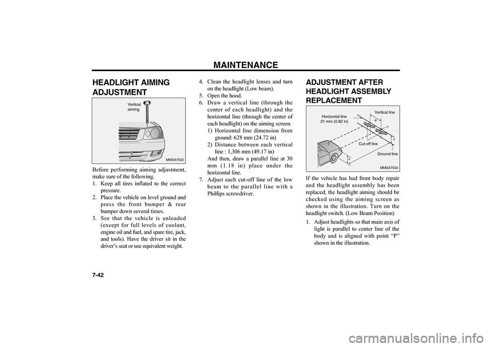
6. Draw a vertical line (through the
center of each headlight) and the
horizontal line (through the center of
each headlight) on the aiming screen.
1) Horizontal line dimension from
ground: 628 mm (24.72 in)
2) Distance between each vertical
line : 1,306 mm (49.17 in)
And then, draw a parallel line at 30
mm (1.18 in) place under the
horizontal line.
7. Adjust each cut-off line of the low
beam to the parallel line with a
Phillips screwdriver.
ADJUSTMENT AFTER
HEADLIGHT ASSEMBLY
REPLACEMENTIf the vehicle has had front body repair
and the headlight assembly has been
replaced, the headlight aiming should be
checked using the aiming screen as
shown in the illustration. Turn on the
headlight switch. (Low Beam Position)
1. Adjust headlights so that main axis of
light is parallel to center line of the
body and is aligned with point “P”
shown in the illustration.
MMSA7032
Vertical
aiming
HH W
P
MMSA7033
Horizontal line
21 mm (0.82 in)
Cut-off line
Ground line Vertical line
MS-CNA-Eng 7.QXD 7/25/2005 5:09 PM Page 42