USB KIA NIRO HYBRID EV 2022 Owners Manual
[x] Cancel search | Manufacturer: KIA, Model Year: 2022, Model line: NIRO HYBRID EV, Model: KIA NIRO HYBRID EV 2022Pages: 684, PDF Size: 9.67 MB
Page 64 of 684
25
Your vehicle at a glance
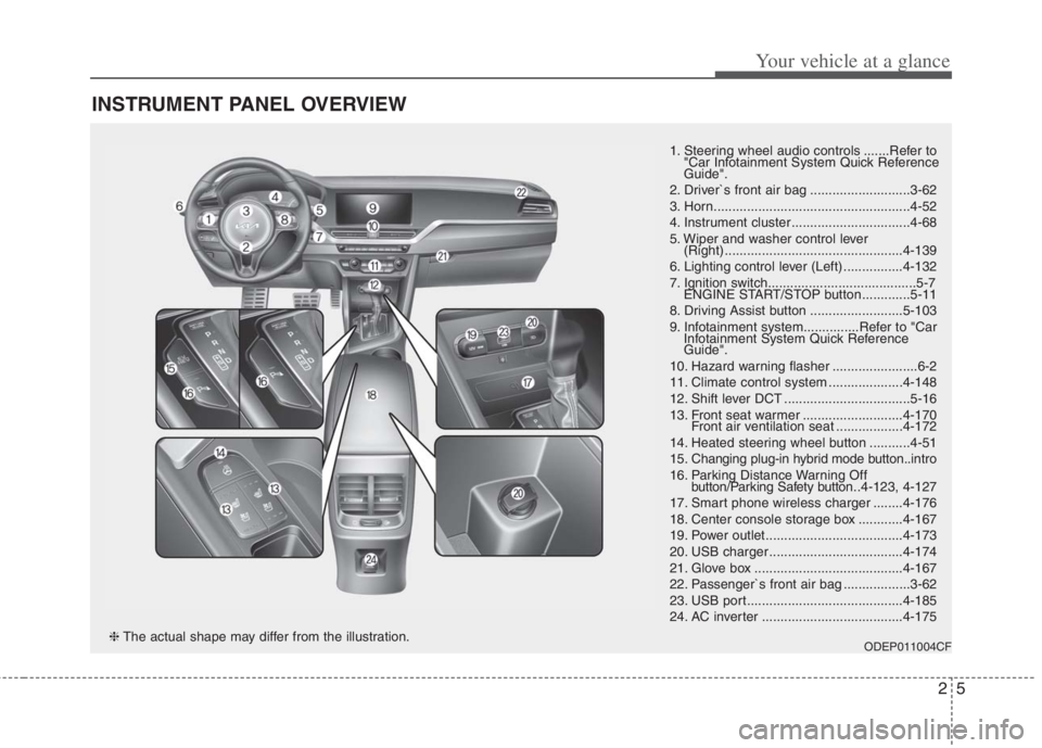
INSTRUMENT PANEL OVERVIEW
1. Steering wheel audio controls .......Refer to
"Car Infotainment System Quick Reference
Guide".
2. Driver`s front air bag ...........................3-62
3. Horn.....................................................4-52
4. Instrument cluster ................................4-68
5. Wiper and washer control lever
(Right) ................................................4-139
6. Lighting control lever (Left) ................4-132
7. Ignition switch........................................5-7
ENGINE START/STOP button .............5-11
8. Driving Assist button .........................5-103
9. Infotainment system...............Refer to "Car
Infotainment System Quick Reference
Guide".
10. Hazard warning flasher .......................6-2
11. Climate control system ....................4-148
12. Shift lever DCT ..................................5-16
13. Front seat warmer ...........................4-170
Front air ventilation seat ..................4-172
14. Heated steering wheel button ...........4-51
15. Changing plug-in hybrid mode button..intro
16. Parking Distance Warning Off
button/Parking Safety button..4-123, 4-127
17. Smart phone wireless charger ........4-176
18. Center console storage box ............4-167
19. Power outlet.....................................4-173
20. USB charger ....................................4-174
21. Glove box ........................................4-167
22. Passenger`s front air bag ..................3-62
23. USB port..........................................4-185
24. AC inverter ......................................4-175
ODEP011004CF❈The actual shape may differ from the illustration.
Page 312 of 684
Features of your vehicle
174 4
Only use 12V electric accessories
which are less than 10A in electric
capacity.
Adjust the air-conditioner or heater
to the lowest operating level when
using the power outlet.
Close the cover when not in use.
Some electronic devices can cause
electronic interference when
plugged into a vehicle’s power out-
let. These devices may cause
excessive audio static and malfunc-
tions in other electronic systems or
devices used in your vehicle.
Push the plug in as far as it will go.
If good contact is not made, the
plug may overheat and the fuse
may open.
Plug in battery equipped electronic
devices with reverse current pro-
tection. The current from the bat-
tery may flow into the vehicle’s
electri cal/electronic system and
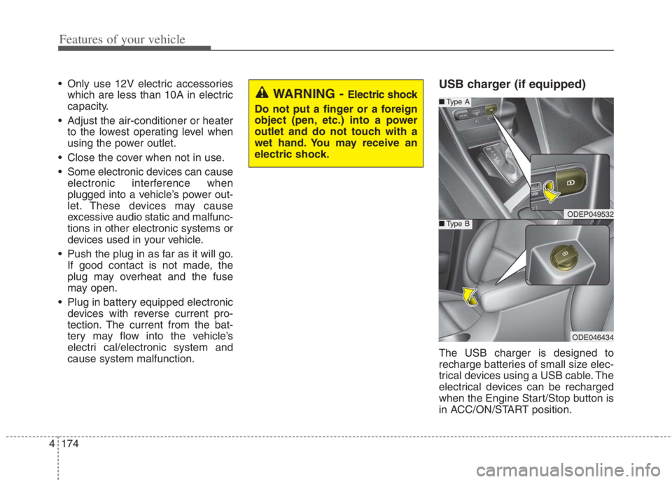
cause system malfunction.USB charger (if equipped)
The USB charger is designed to
recharge batteries of small size elec-
trical devices using a USB cable. The
electrical devices can be recharged
when the Engine Start/Stop button is
in ACC/ON/START position.
WARNING - Electric shock
Do not put a finger or a foreign
object (pen, etc.) into a power
outlet and do not touch with a
wet hand. You may receive an
electric shock.
ODEP049532
■Type A
■Type B
ODE046434
Page 313 of 684
4175
Features of your vehicle
The battery charging state may be
monitored on the electrical device.
Disconnect the USB cable from the
USB port after use.
Some devices are not supported
for fast charging but will be
charged with normal speed.
Use the USB charger when the
engine is running to prevent bat-
tery discharge.
Only devices that fit the USB port
can be used.
The USB charger can be used only
for battery charging purposes.
Battery chargers cannot be
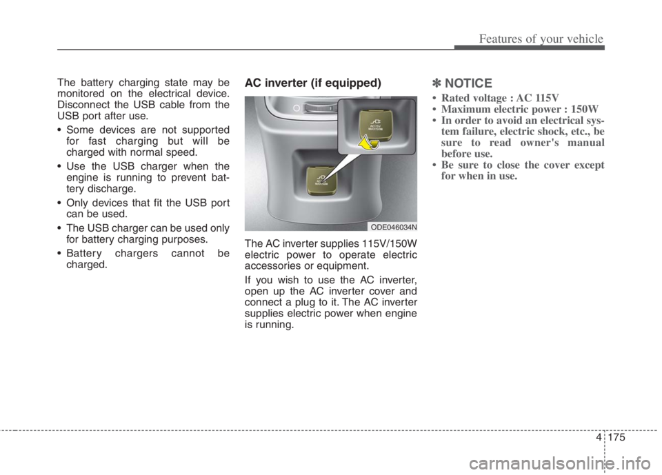
charged.AC inverter (if equipped)
The AC inverter supplies 115V/150W
electric power to operate electric
accessories or equipment.
If you wish to use the AC inverter,
open up the AC inverter cover and
connect a plug to it. The AC inverter
supplies electric power when engine
is running.
✽ ✽
NOTICE
• Rated voltage : AC 115V
• Maximum electric power : 150W
• In order to avoid an electrical sys-
tem failure, electric shock, etc., be
sure to read owner's manual
before use.
• Be sure to close the cover except
for when in use.
ODE046034N
Page 323 of 684
4185
Features of your vehicle
✽
✽NOTICE
If you install an after market HID
head lamp, your vehicle’s audio and
electronic device may malfunction.
❈ If your vehicle is equipped with
Infotainment system, refer to a
separately supplied manual for
detailed information.
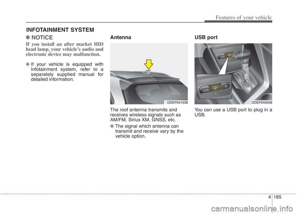
Antenna
The roof antenna transmits and
receives wireless signals such as
AM/FM, Sirius XM, GNSS, etc.
❈The signal which antenna can
transmit and receive vary by the
vehicle option.
USB port
You can use a USB port to plug in a
USB.
INFOTAINMENT SYSTEM
ODEP041438ODEP049439
Page 610 of 684
Maintenance
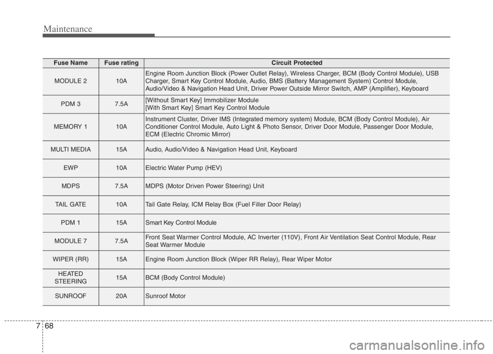
68 7
Fuse NameFuse ratingCircuit Protected
MODULE 210AEngine Room Junction Block (Power Outlet Relay), Wireless Charger, BCM (Body Control Module), USB
Charger, Smart Key Control Module, Audio, BMS (Battery Management System) Control Module,
Audio/Video & Navigation Head Unit, Driver Power Outside Mirror Switch, AMP (Amplifier), Keyboard
PDM 37.5A[Without Smart Key] Immobilizer Module
[With Smart Key] Smart Key Control Module
MEMORY 110AInstrument Cluster, Driver IMS (Integrated memory system) Module, BCM (Body Control Module), Air
Conditioner Control Module, Auto Light & Photo Sensor, Driver Door Module, Passenger Door Module,
ECM (Electric Chromic Mirror)
MULTI MEDIA15AAudio, Audio/Video & Navigation Head Unit, Keyboard
EWP10AElectric Water Pump (HEV)
MDPS7.5AMDPS (Motor Driven Power Steering) Unit
TAIL GATE10ATail Gate Relay, ICM Relay Box (Fuel Filler Door Relay)
PDM 115ASmart Key Control Module
MODULE 77.5AFront Seat Warmer Control Module, AC Inverter (110V), Front Air Ventilation Seat Control Module, Rear
Seat Warmer Module
WIPER (RR)15AEngine Room Junction Block (Wiper RR Relay), Rear Wiper Motor
HEATED
STEERING15ABCM (Body Control Module)
SUNROOF20ASunroof Motor
Page 614 of 684
Maintenance
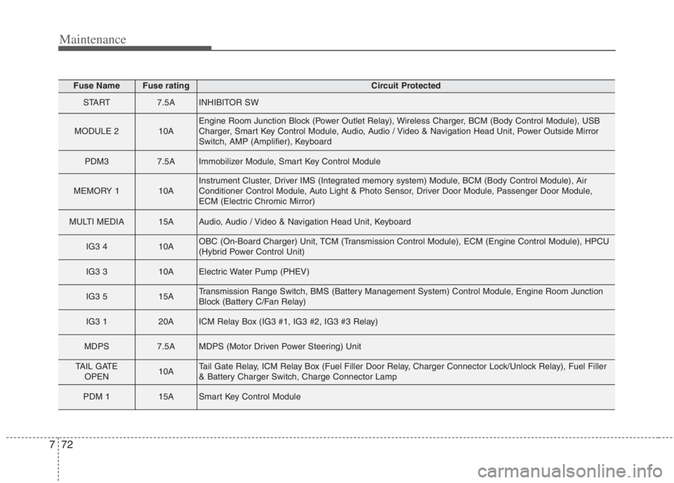
72 7
Fuse NameFuse ratingCircuit Protected
START7.5AINHIBITOR SW
MODULE 210AEngine Room Junction Block (Power Outlet Relay), Wireless Charger, BCM (Body Control Module), USB
Charger, Smart Key Control Module, Audio, Audio / Video & Navigation Head Unit, Power Outside Mirror
Switch, AMP (Amplifier), Keyboard
PDM37.5AImmobilizer Module, Smart Key Control Module
MEMORY 110AInstrument Cluster, Driver IMS (Integrated memory system) Module, BCM (Body Control Module), Air
Conditioner Control Module, Auto Light & Photo Sensor, Driver Door Module, Passenger Door Module,
ECM (Electric Chromic Mirror)
MULTI MEDIA15AAudio, Audio / Video & Navigation Head Unit, Keyboard
IG3 410AOBC (On-Board Charger) Unit, TCM (Transmission Control Module), ECM (Engine Control Module), HPCU
(Hybrid Power Control Unit)
IG3 310AElectric Water Pump (PHEV)
IG3 515ATransmission Range Switch, BMS (Battery Management System) Control Module, Engine Room Junction
Block (Battery C/Fan Relay)
IG3 120AICM Relay Box (IG3 #1, IG3 #2, IG3 #3 Relay)
MDPS7.5AMDPS (Motor Driven Power Steering) Unit
TAIL GATE
OPEN10ATail Gate Relay, ICM Relay Box (Fuel Filler Door Relay, Charger Connector Lock/Unlock Relay), Fuel Filler
& Battery Charger Switch, Charge Connector Lamp
PDM 115ASmart Key Control Module
Page 679 of 684

Index
6I
If the engine stalls while driving. . . . . . . . . . . . . . . . 6-3
If you have a flat tire while driving . . . . . . . . . . . . . 6-3
Infotainment system . . . . . . . . . . . . . . . . . . . . . . . . . . 4-185
Antenna . . . . . . . . . . . . . . . . . . . . . . . . . . . . . . . . . 4-185
How vehicle radio works . . . . . . . . . . . . . . . . . . . . 4-186
USB port. . . . . . . . . . . . . . . . . . . . . . . . . . . . . . . . . 4-185
Instrument cluster . . . . . . . . . . . . . . . . . . . . . . . . . . . . . 4-68
Dual clutch transmission shift indicator . . . . . . . . . 4-76
Gauges . . . . . . . . . . . . . . . . . . . . . . . . . . . . . . . . . . . 4-70
Instrument Cluster Control. . . . . . . . . . . . . . . . . . . . 4-70
Instrument panel overview . . . . . . . . . . . . . . . . . . . . . . . 2-5
Interior features. . . . . . . . . . . . . . . . . . . . . . . . . . . . . . 4-170
AC inverter . . . . . . . . . . . . . . . . . . . . . . . . . . . . . . . 4-175
Air ventilation seat . . . . . . . . . . . . . . . . . . . . . . . . . 4-172
Cargo security screen . . . . . . . . . . . . . . . . . . . . . . . 4-182
Clothes hanger . . . . . . . . . . . . . . . . . . . . . . . . . . . . 4-180
Cup holder . . . . . . . . . . . . . . . . . . . . . . . . . . . . . . . 4-170
Floor mat anchor(s) . . . . . . . . . . . . . . . . . . . . . . . . 4-180
Luggage net holder. . . . . . . . . . . . . . . . . . . . . . . . . 4-181
Power outlet . . . . . . . . . . . . . . . . . . . . . . . . . . . . . . 4-173
Seat warmer . . . . . . . . . . . . . . . . . . . . . . . . . . . . . . 4-170
Sun visor. . . . . . . . . . . . . . . . . . . . . . . . . . . . . . . . . 4-173
USB charger . . . . . . . . . . . . . . . . . . . . . . . . . . . . . . 4-174
Wireless smart phone charging system . . . . . . . . . 4-176
Interior lights . . . . . . . . . . . . . . . . . . . . . . . . . . . . . . . 4-143
Automatic turn off function . . . . . . . . . . . . . . . . . . 4-143
Liftgate room lamp. . . . . . . . . . . . . . . . . . . . . . . . . 4-145
Map lamp . . . . . . . . . . . . . . . . . . . . . . . . . . . . . . . 4-143Room lamp . . . . . . . . . . . . . . . . . . . . . . . . . . . . . . . 4-144
Vanity mirror lamp . . . . . . . . . . . . . . . . . . . . . . . . . 4-145
Interior overview. . . . . . . . . . . . . . . . . . . . . . . . . . . . . . . 2-4
Key positions . . . . . . . . . . . . . . . . . . . . . . . . . . . . . . . . . 5-7
Ignition switch position . . . . . . . . . . . . . . . . . . . . . . . 5-7
Illuminated ignition switch . . . . . . . . . . . . . . . . . . . . 5-7
Starting the hybrid system . . . . . . . . . . . . . . . . . . . . . 5-9
Lane Following Assist (LFA) . . . . . . . . . . . . . . . . . . . 5-132
Lane Following Assist malfunction . . . . . . . . . . . . 5-136
Lane Following Assist operation . . . . . . . . . . . . . . 5-133
Limitation of Lane Following Assist . . . . . . . . . . . 5-136
Lane Keeping Assist (LKA) . . . . . . . . . . . . . . . . . . . . . 5-71
Lane Keeping Assist activation . . . . . . . . . . . . . . . . 5-74
Lane Keeping Assist malfunction . . . . . . . . . . . . . . 5-77
Lane Keeping Assist operation . . . . . . . . . . . . . . . . 5-72
Lane Keeping Assist setting . . . . . . . . . . . . . . . . . . . 5-73
LCD Display . . . . . . . . . . . . . . . . . . . . . . . . . . . . . . . . . 4-78
LCD Display Control . . . . . . . . . . . . . . . . . . . . . . . . 4-78
LCD Display Modes . . . . . . . . . . . . . . . . . . . . . . . . 4-79
Trip modes (Trip computer) . . . . . . . . . . . . . . . . . . . 4-91
Warning messages . . . . . . . . . . . . . . . . . . . . . . . . . . 4-96
K
L