driver KIA NIRO PHEV 2018 Owners Manual
[x] Cancel search | Manufacturer: KIA, Model Year: 2018, Model line: NIRO PHEV, Model: KIA NIRO PHEV 2018Pages: 616, PDF Size: 18.3 MB
Page 468 of 616
What to do in an emergency
32
7
Emergency towing precautions
Turn the ignition switch to ACC so
the steering wheel isn’t locked.
Place the transaxle shift lever in N (Neutral).
Release the parking bake.
Press the brake pedal with more force than normal since you will
have reduced brake performance.
More steering effort will be required because the power steer-
ing system will be disabled.
If you are driving down a long hill, the brakes may overheat and brake
performance will be reduced. Stop
often and let the brakes cool off. If the car is being towed with all
four wheels on the ground, it can
be towed only from the front. Be
sure that the transaxle is in neutral.
Be sure the steering is unlocked by
placing the ignition switch in the
ACC position. A driver must be in
the towed vehicle to operate the
steering and brakes.
CAUTION - Dual clutchtransmission
To avoid serious damage to the
dual clutch transmission, limitthe vehicle speed to 10 mph(15 km/h) and drive less than 1mile (1.5 km) when towing.
Before towing, check the dual clutch transmission for fluidleaks under your vehicle. If thedual clutch transmission fluidis leaking, flatbed equipmentor a towing dolly must beused.
Page 516 of 616
847
Maintenance
When recharging the battery,
observe the following precautions:
The battery must be removed fromthe vehicle and placed in an area
with good ventilation.
Do not allow cigarettes, sparks, or flame near the battery.
Watch the battery during charging, and stop or reduce the charging
rate if the battery cells begin
gassing (boiling) violently or if the
temperature of the electrolyte of
any cell exceeds 120°F (49°C).
Wear eye protection when check- ing the battery during charging.
Disconnect the battery charger in the following order.
1. Turn off the battery charger main switch.
2. Unhook the negative clamp from the negative battery terminal.
3. Unhook the positive clamp from the positive battery terminal. Before performing maintenance or
recharging the battery, turn off all
accessories and stop the engine.
The negative battery cable must be removed first and installed last
when the battery is disconnected.Reset items
Items should be reset after the bat-
tery has been discharged or the bat-
tery has been disconnected.
Auto up/down window (See chapter 4)
Sunroof (See chapter 4)
Trip computer (See chapter 4)
Climate control system (See chapter 4)
Driver position memory system (See chapter 3)
Audio (See chapter 5)
Page 517 of 616
Maintenance
48
8
TIRES AND WHEELS
Tire care
For proper maintenance, safety, and
maximum fuel economy, you must
always maintain recommended tire
inflation pressures and stay within
the load limits and weight distribution
recommended for your vehicle.
Recommended cold tire infla-
tion pressures
All tire pressures (including the
spare) should be checked when the
tires are cold. “Cold Tires” means the
vehicle has not been driven for at
least three hours or driven less than
one mile (1.6 km).
Recommended pressures must be
maintained for the best ride, top vehi-
cle handling, and minimum tire wear.
For recommended inflation pressure
refer to “Tire and wheels” in chapter
9. All specifications (sizes and pres-
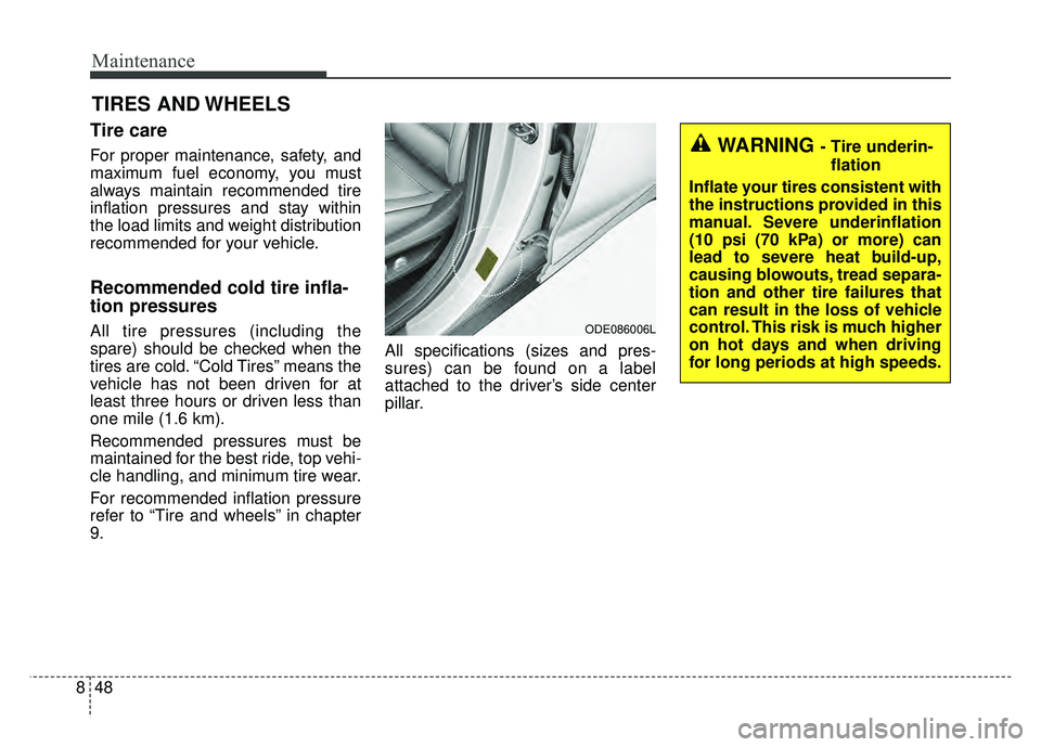
sures) can be found on a label
attached to the driver’s side center
pillar.
WARNING - Tire underin-
flation
Inflate your tires consistent with
the instructions provided in this
manual. Severe underinflation
(10 psi (70 kPa) or more) can
lead to severe heat build-up,
causing blowouts, tread separa-
tion and other tire failures that
can result in the loss of vehicle
control. This risk is much higher
on hot days and when driving
for long periods at high speeds.
ODE086006L
Page 519 of 616
Maintenance
50
8
Remove the valve cap from the tire
valve stem. Press the tire gauge firm-
ly onto the valve to get a pressure
measurement. If the cold tire inflation
pressure matches the recommended
pressure on the tire and loading
information label, no further adjust-
ment is necessary. If the pressure is
low, add air until you reach the rec-
ommended amount.
If you overfill the tire, release air by
pushing on the metal stem in the
center of the tire valve. Recheck the
tire pressure with the tire gauge. Be
sure to put the valve caps back on
the valve stems. They help prevent
leaks by keeping out dirt and mois-
ture. Inspect your tires frequently for
proper inflation as well as wear and
damage. Always use a tire pres-
sure gauge.
Tires with too much or too little pressure wear unevenly causing
poor handling, loss of vehicle con-
trol, and sudden tire failure leading
to accidents, injuries, and even
death. The recommended cold tire
pressure for your vehicle can be
found in this manual and on the tire
label located on the driver's side
center pillar.
Remember to check the pressure of your spare tire. Kia recommends
that you check the spare every
time you check the pressure of the
other tires on your vehicle.Tire rotation
To equalize tread wear, it is recom-
mended that the tires be rotated
every 7,500 miles (12,000 km) or
sooner if irregular wear develops.
During rotation, check the tires for
correct balance.
When rotating tires, check for uneven
wear and damage. Abnormal wear is
usually caused by incorrect tire pres-
sure, improper wheel alignment, out-
of-balance wheels, severe braking or
severe cornering. Look for bumps or
bulges in the tread or side of tire.
Replace the tire if you find either of
these conditions. Replace the tire if
fabric or cord is visible. After rotation,
be sure to bring the front and rear tire
pressures to specification and check
lug nut tightness.
Refer to “Tire and wheels” in chapter
9.
Page 532 of 616
863
Maintenance
FUSES
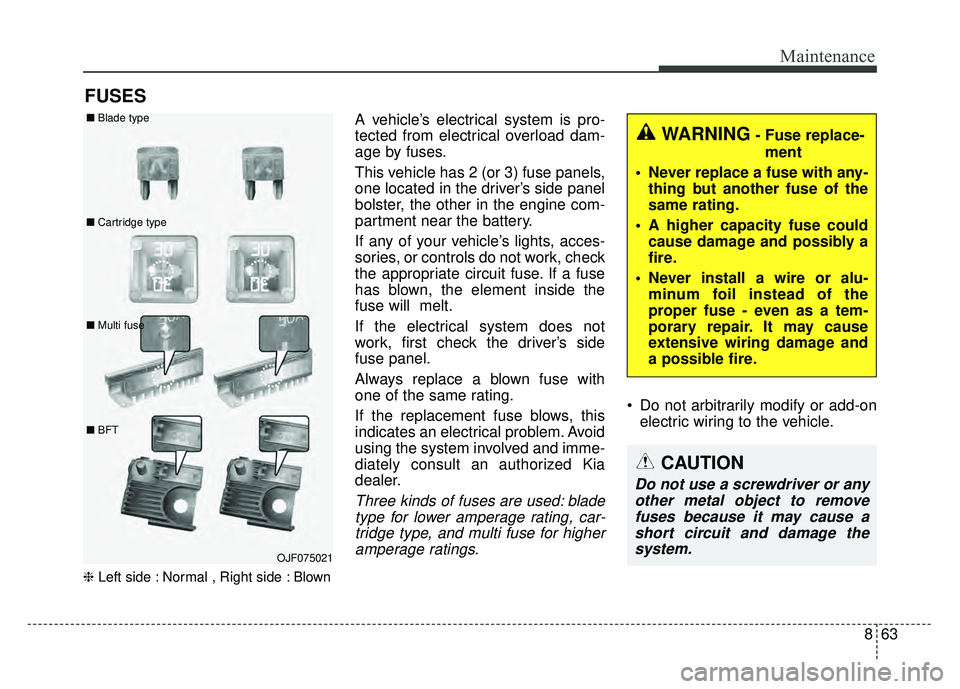
❈Left side : Normal , Right side : Blown
A vehicle’s electrical system is pro-
tected from electrical overload dam-
age by fuses.
This vehicle has 2 (or 3) fuse panels,
one located in the driver’s side panel
bolster, the other in the engine com-
partment near the battery.
If any of your vehicle’s lights, acces-
sories, or controls do not work, check
the appropriate circuit fuse. If a fuse
has blown, the element inside the
fuse will melt.
If the electrical system does not
work, first check the driver’s side
fuse panel.
Always replace a blown fuse with
one of the same rating.
If the replacement fuse blows, this
indicates an electrical problem. Avoid
using the system involved and imme-
diately consult an authorized Kia
dealer.
Three kinds of fuses are used: blade
type for lower amperage rating, car-tridge type, and multi fuse for higheramperage ratings.
Do not arbitrarily modify or add-on electric wiring to the vehicle.
WARNING- Fuse replace-
ment
Never replace a fuse with any- thing but another fuse of the
same rating.
A higher capacity fuse could cause damage and possibly a
fire.
Never install a wire or alu- minum foil instead of the
proper fuse - even as a tem-
porary repair. It may cause
extensive wiring damage and
a possible fire.
CAUTION
Do not use a screwdriver or anyother metal object to removefuses because it may cause ashort circuit and damage thesystem.
OJF075021
■
Blade type
■ Cartridge type
■ Multi fuse
■ BFT
Page 538 of 616
869
Maintenance
Driver’s side fuse panel
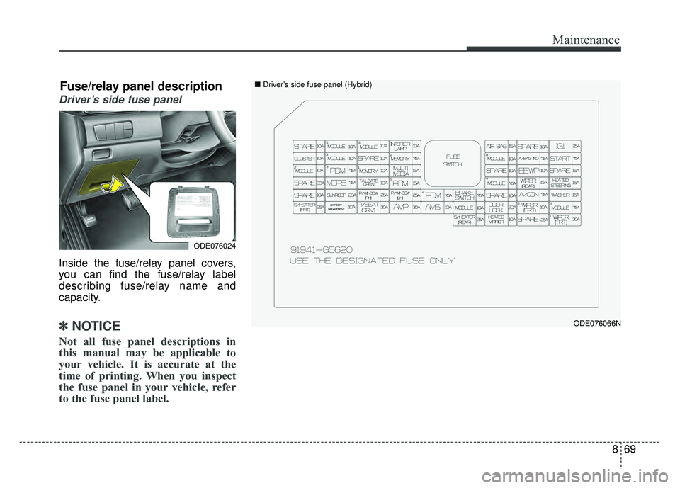
Inside the fuse/relay panel covers,
you can find the fuse/relay label
describing fuse/relay name and
capacity.
✽ ✽NOTICE
Not all fuse panel descriptions in
this manual may be applicable to
your vehicle. It is accurate at the
time of printing. When you inspect
the fuse panel in your vehicle, refer
to the fuse panel label.
ODE076066N
ODE076024
Fuse/relay panel description■ Driver’s side fuse panel (Hybrid)
Page 539 of 616
Maintenance
70
8
Driver’s side fuse panel
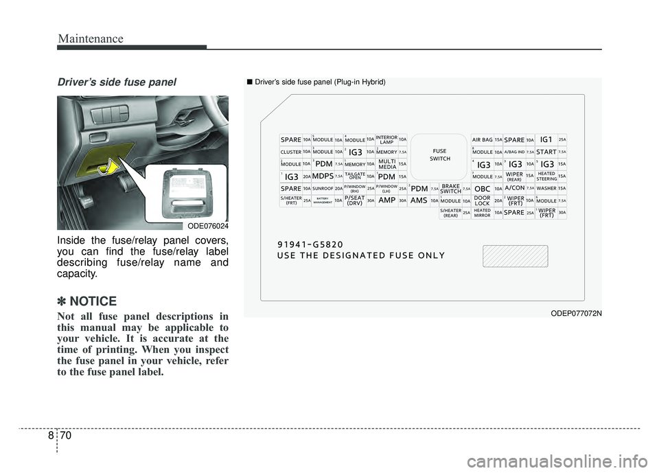
Inside the fuse/relay panel covers,
you can find the fuse/relay label
describing fuse/relay name and
capacity.
✽ ✽
NOTICE
Not all fuse panel descriptions in
this manual may be applicable to
your vehicle. It is accurate at the
time of printing. When you inspect
the fuse panel in your vehicle, refer
to the fuse panel label.ODEP077072N
■ Driver’s side fuse panel (Plug-in Hybrid)
ODE076024
Page 540 of 616

871
Maintenance
Instrument panel (Driver’s side fuse panel) (Hybrid)
Fuse NameFuse ratingCircuit Protected
MODULE 510A
Electro Chromic Mirror, Audio/Video & Navigation Head Unit, Audio, Driver IMS (Integrated memory system)
Module, VESS (Virtual Engine Sound System) Unit, Shift Lever Indicator, Air Conditioner Control Module,
Rear Seat Warmer Control Module, Front Air Ventilation Seat Control Module, Front Seat Warmer Control
Module, Head Lamp LH/RH
MODULE 410ALane Keeping Assist Control Module, Crash Pad Switch, AEB Module, Blind Spot Detection Radar LH/RH,
AFLS (Adaptive Front Lighting System) Unit
INTERIORLAMP10AFront Vanity Lamp LH/RH, Room Lamp, Overhead Console Lamp, Ignition Key ILL. & Door Warning Switch,
Luggage Lamp
A/BAG15ASRS (Supplemental Restraint System) Control Module, Passenger Occupant Detection Sensor
IG 125AEngine Room Junction Block (Fuse - DCT4, HPCU2, ACTIVE HYDRAULIC BOOSTER3, ECU3)
CLUSTER10AInstrument Cluster
MODULE 310ABCM (Body Control Module), DCT (Dual Clutch Transmission) Shift Lever, Stop Lamp Switch, Driver Door
Module, Passenger Door Module
MEMORY 27.5AActive Air Flap Unit
MODULE 810AActive Air Flap Unit, Electric Water Pump (Engine), VPD Sensor, Engine Room Junction Block (Battery
C/Fan Relay), BMS (Battery Management System) Control Module
A/BAG IND7.5AAir Conditioner Control Module, Instrument Cluster
START7.5A[Without Smart Key & Without Immobilizer] Burglar alarm Relay
[With Smart Key/With Immobilizer] Inhibitor Switch
Page 541 of 616

Maintenance
72
8
Fuse NameFuse ratingCircuit Protected
MODULE 210AEngine Room Junction Block (Power Outlet Relay), Wireless Charger, BCM (Body Control Module), USB
Charger, Smart Key Control Module, Audio, BMS (Battery Management System) Control Module,
Audio/Video & Navigation Head Unit, Driver Power Outside Mirror Switch, AMP (Amplifier)
PDM 37.5A[Without Smart Key] Immobilizer Module
[With Smart Key] Smart Key Control Module
MEMORY 110AInstrument Cluster, Driver IMS (Integrated memory system) Module, BCM (Body Control Module), Air
Conditioner Control Module, Auto Light & Photo Sensor, Driver Door Module, Passenger Door Module, ICM
Relay Box (Outside Mirror Folding/Unfolding Relay), Wireless Charger
MULTI MEDIA15AAudio, Audio/Video & Navigation Head Unit
EEWP10AElectric Water Pump (HEV)
MDPS7.5AMDPS (Motor Driven Power Steering) Unit
TAIL GATE10ATail Gate Relay, ICM Relay Box (Fuel Filler Door Relay), Fuel Filler Switch
PDM 115ASmart Key Control Module
MODULE 77.5AFront Seat Warmer Control Module, AC Inverter (220V), Front Air Ventilation Seat Control Module, Rear
Seat Warmer Module, AC Inverter Module
WIPER (REAR)15AEngine Room Junction Block (Wiper RR Relay), Rear Wiper Motor
HEATED
STEERING15ABCM (Body Control Module)
SUNROOF20ASunroof Motor
Page 542 of 616
873
Maintenance
Fuse NameFuse ratingCircuit Protected
P/WINDOW RH25APower Window (RH) Relay, Passenger Safety Power Window Module
P/WINDOW LH25APower Window (LH) Relay, Driver Safety Power Window Module
PDM 27.5A[Without Smart Key] Immobilizer Module
[With Smart Key] Smart Key Control Module, Start/Stop Button Switch
BRAKE SWITCH7.5AStop Lamp Switch, Smart Key Control Module
A/CON7.5AAir Conditioner Control Module, Electronic Air Conditioner Compressor, Ionizer, Engine Room Junction
Block (Blower Relay, PTC Heater1 Relay, PTC Heater2 Relay)
WASHER15AMultifunction Switch
S/HEATER (FRT)25AFront Seat Warmer Control Module, Front Air Ventilation Seat Control Module
BATTERY
MANAGEMENT10ABMS (Battery Management System) Control Module
P/SEAT (DRV)30A[Without IMS] Driver Seat Manual Switch
[With IMS] Driver Seat Manual Switch, Driver IMS (Integrated memory system) Module
AMP30AAMP (Amplifier)
AMS10ANot Used
MODULE 110AData Link Connector, AEB Module, Hazard Switch, Driver/Passenger Door Module, Driver/Passenger Smart
Key Outside Handle, Key Interlock, Natural Vacuum Leak Detection