fuel KIA Optima 2015 4.G Workshop Manual
[x] Cancel search | Manufacturer: KIA, Model Year: 2015, Model line: Optima, Model: KIA Optima 2015 4.GPages: 487, PDF Size: 13.4 MB
Page 436 of 487
769
Maintenance
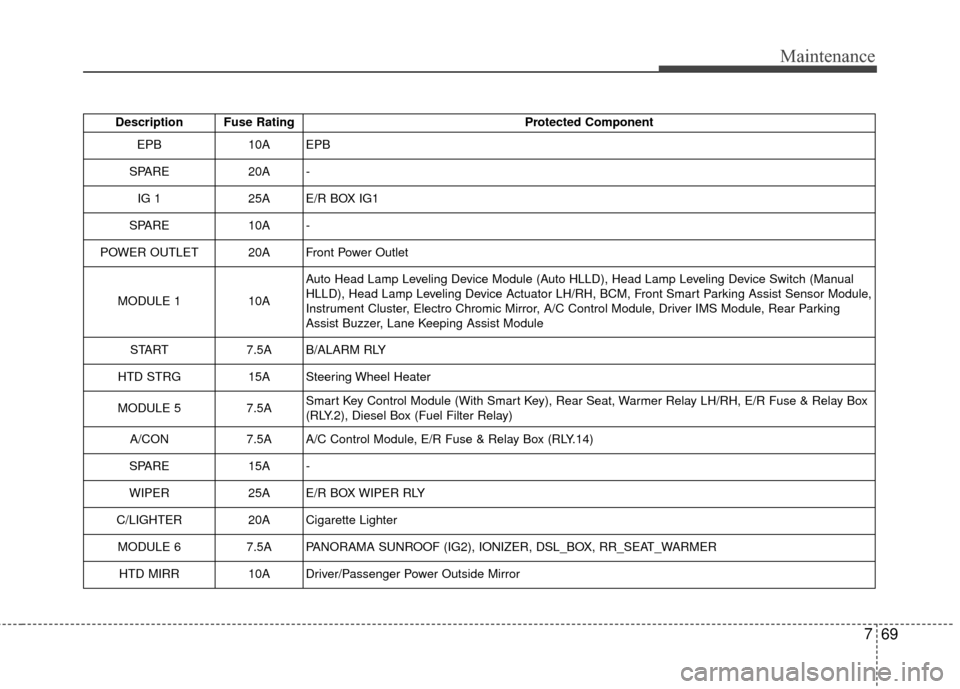
Description Fuse RatingProtected Component
EPB10AEPB
SPARE20A-
IG 125AE/R BOX IG1
SPARE 10A -
POWER OUTLET 20A Front Power Outlet
MODULE 1 10A Auto Head Lamp Leveling Device Module (Auto HLLD), Head Lamp Leveling Device Switch (Manual
HLLD), Head Lamp Leveling Device Actuator LH/RH, BCM, Front Smart Parking Assist Sensor Module,
Instrument Cluster, Electro Chromic Mirror, A/C Control Module, Driver IMS Module, Rear Parking
Assist Buzzer, Lane Keeping Assist Module
START 7.5A B/ALARM RLY
HTD STRG 15A Steering Wheel Heater
MODULE 5 7.5A Smart Key Control Module (With Smart Key), Rear Seat, Warmer Relay LH/RH, E/R Fuse & Relay Box
(RLY.2), Diesel Box (Fuel Filter Relay)
A/CON 7.5A A/C Control Module, E/R Fuse & Relay Box (RLY.14)
SPARE 15A -
WIPER 25A E/R BOX WIPER RLY
C/LIGHTER 20A Cigarette Lighter MODULE 6 7.5A PANORAMA SUNROOF (IG2), IONIZER, DSL_BOX, RR_SEAT_WARMER HTD MIRR 10A Driver/Passenger Power Outside Mirror
Page 438 of 487
771
Maintenance
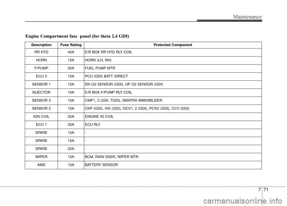
Engine Compartment fuse panel (for theta 2.4 GDI)
Description Fuse RatingProtected Component
RR HTD 40A E/R BOX RR HTD RLY COIL
HORN 15A HORN (LH, RH)
F/PUMP 20A FUEL PUMP MTR
ECU 3 15A PCU (GDI) BATT. DIRECT
SENSOR 1 15A DN O2 SENSOR (GDI), UP O2 SENSOR (GDI) INJECTOR 10A E/R BOX F/PUMP RLY COIL
SENSOR 3 10A CMP1, 2 (GDI, TGDI), SMATRA IMMOBILIZER
SENSOR 2 10A CKP (GDI), VIS (GDI), OCV1, 2 (GDI), PCSV (GDI), CCV (GDI) IGN COIL 20A ENGINE IG COIL ECU 1 30A ECU RLY
SPARE 10A -
SPARE 15A -
SPARE 20A -
WIPER 10A BCM, RAIN SNSR, WIPER MTR
AMS 10A BATTERY SENSOR
Page 442 of 487
775
Maintenance
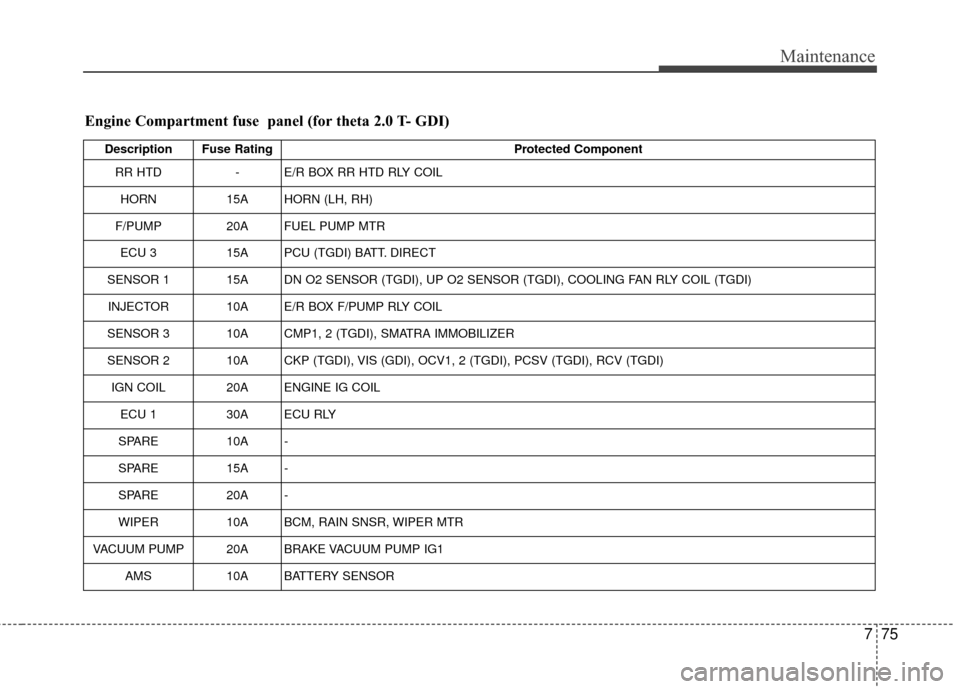
Description Fuse RatingProtected Component
RR HTD - E/R BOX RR HTD RLY COIL
HORN 15A HORN (LH, RH)
F/PUMP 20A FUEL PUMP MTR
ECU 3 15A PCU (TGDI) BATT. DIRECT
SENSOR 1 15A DN O2 SENSOR (TGDI), UP O2 SENSOR (TGDI), COOLING FAN RLY COIL (TGDI) INJECTOR 10A E/R BOX F/PUMP RLY COIL
SENSOR 3 10A CMP1, 2 (TGDI), SMATRA IMMOBILIZER
SENSOR 2 10A CKP (TGDI), VIS (GDI), OCV1, 2 (TGDI), PCSV (TGDI), RCV (TGDI) IGN COIL 20A ENGINE IG COIL ECU 1 30A ECU RLY
SPARE 10A -
SPARE 15A -
SPARE 20A -
WIPER 10A BCM, RAIN SNSR, WIPER MTR
VACUUM PUMP 20A BRAKE VACUUM PUMP IG1 AMS 10A BATTERY SENSOR
Engine Compartment fuse panel (for theta 2.0 T- GDI)
Page 461 of 487
Maintenance
94
7
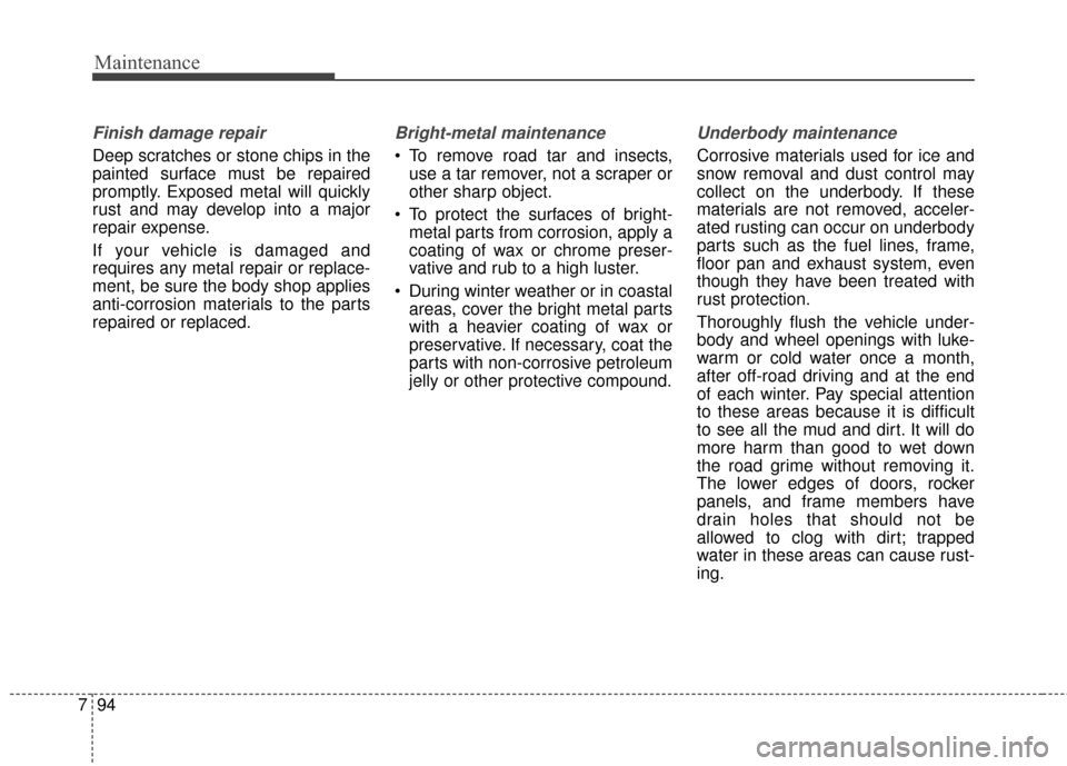
Finish damage repair
Deep scratches or stone chips in the
painted surface must be repaired
promptly. Exposed metal will quickly
rust and may develop into a major
repair expense.
If your vehicle is damaged and
requires any metal repair or replace-
ment, be sure the body shop applies
anti-corrosion materials to the parts
repaired or replaced.
Bright-metal maintenance
To remove road tar and insects,
use a tar remover, not a scraper or
other sharp object.
To protect the surfaces of bright- metal parts from corrosion, apply a
coating of wax or chrome preser-
vative and rub to a high luster.
During winter weather or in coastal areas, cover the bright metal parts
with a heavier coating of wax or
preservative. If necessary, coat the
parts with non-corrosive petroleum
jelly or other protective compound.
Underbody maintenance
Corrosive materials used for ice and
snow removal and dust control may
collect on the underbody. If these
materials are not removed, acceler-
ated rusting can occur on underbody
parts such as the fuel lines, frame,
floor pan and exhaust system, even
though they have been treated with
rust protection.
Thoroughly flush the vehicle under-
body and wheel openings with luke-
warm or cold water once a month,
after off-road driving and at the end
of each winter. Pay special attention
to these areas because it is difficult
to see all the mud and dirt. It will do
more harm than good to wet down
the road grime without removing it.
The lower edges of doors, rocker
panels, and frame members have
drain holes that should not be
allowed to clog with dirt; trapped
water in these areas can cause rust-
ing.
Page 466 of 487
799
Maintenance
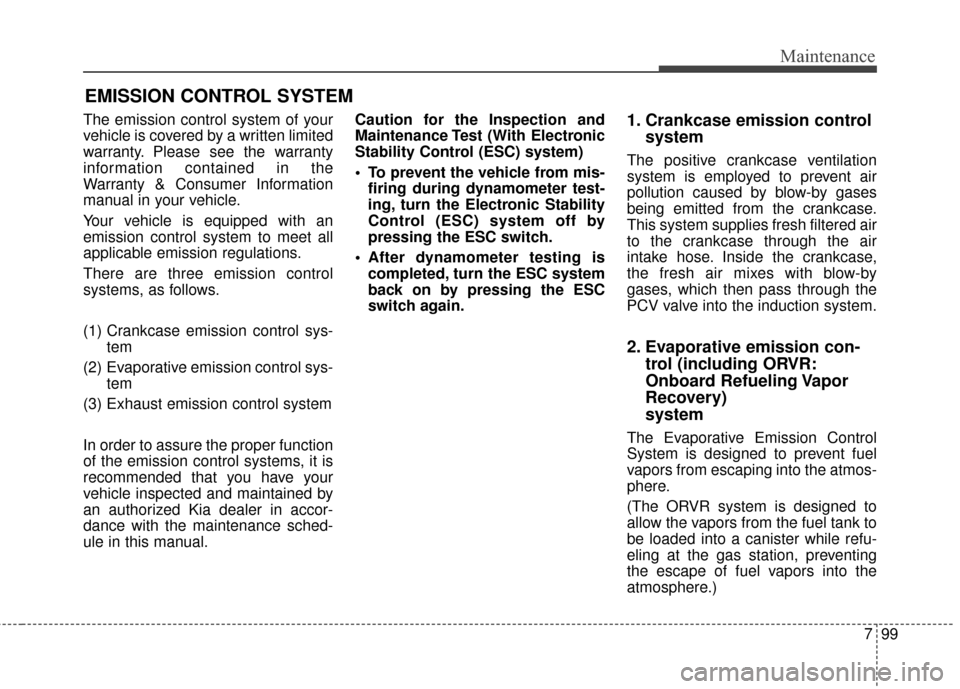
EMISSION CONTROL SYSTEM
The emission control system of your
vehicle is covered by a written limited
warranty. Please see the warranty
information contained in the
Warranty & Consumer Information
manual in your vehicle.
Your vehicle is equipped with an
emission control system to meet all
applicable emission regulations.
There are three emission control
systems, as follows.
(1) Crankcase emission control sys-tem
(2) Evaporative emission control sys- tem
(3) Exhaust emission control system
In order to assure the proper function
of the emission control systems, it is
recommended that you have your
vehicle inspected and maintained by
an authorized Kia dealer in accor-
dance with the maintenance sched-
ule in this manual. Caution for the Inspection and
Maintenance Test (With Electronic
Stability Control (ESC) system)
To prevent the vehicle from mis-
firing during dynamometer test-
ing, turn the Electronic Stability
Control (ESC) system off by
pressing the ESC switch.
After dynamometer testing is completed, turn the ESC system
back on by pressing the ESC
switch again.1. Crankcase emission control system
The positive crankcase ventilation
system is employed to prevent air
pollution caused by blow-by gases
being emitted from the crankcase.
This system supplies fresh filtered air
to the crankcase through the air
intake hose. Inside the crankcase,
the fresh air mixes with blow-by
gases, which then pass through the
PCV valve into the induction system.
2. Evaporative emission con-trol (including ORVR:
Onboard Refueling Vapor
Recovery)
system
The Evaporative Emission Control
System is designed to prevent fuel
vapors from escaping into the atmos-
phere.
(The ORVR system is designed to
allow the vapors from the fuel tank to
be loaded into a canister while refu-
eling at the gas station, preventing
the escape of fuel vapors into the
atmosphere.)
Page 467 of 487
Maintenance
100
7
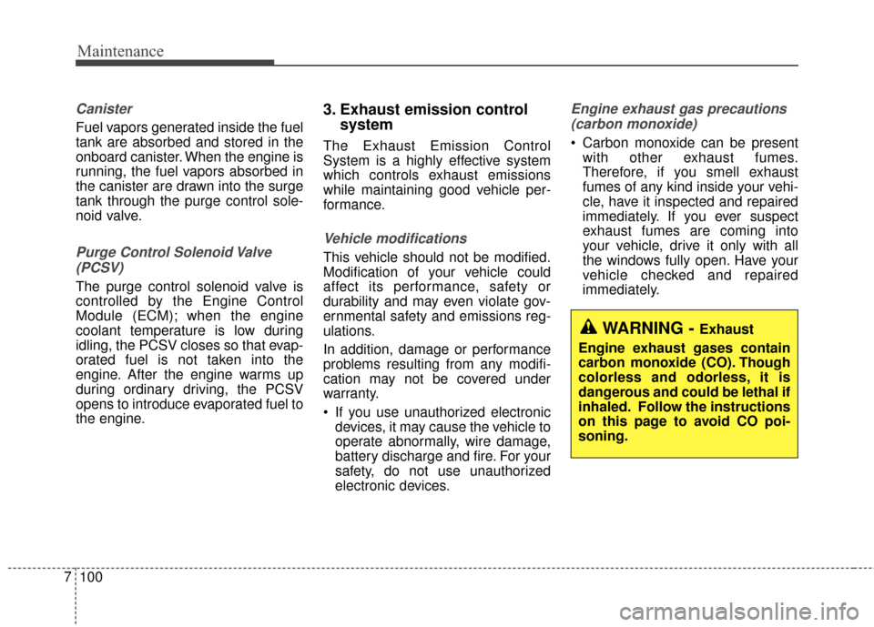
Canister
Fuel vapors generated inside the fuel
tank are absorbed and stored in the
onboard canister. When the engine is
running, the fuel vapors absorbed in
the canister are drawn into the surge
tank through the purge control sole-
noid valve.
Purge Control Solenoid Valve
(PCSV)
The purge control solenoid valve is
controlled by the Engine Control
Module (ECM); when the engine
coolant temperature is low during
idling, the PCSV closes so that evap-
orated fuel is not taken into the
engine. After the engine warms up
during ordinary driving, the PCSV
opens to introduce evaporated fuel to
the engine.
3. Exhaust emission control system
The Exhaust Emission Control
System is a highly effective system
which controls exhaust emissions
while maintaining good vehicle per-
formance.
Vehicle modifications
This vehicle should not be modified.
Modification of your vehicle could
affect its performance, safety or
durability and may even violate gov-
ernmental safety and emissions reg-
ulations.
In addition, damage or performance
problems resulting from any modifi-
cation may not be covered under
warranty.
If you use unauthorized electronic
devices, it may cause the vehicle to
operate abnormally, wire damage,
battery discharge and fire. For your
safety, do not use unauthorized
electronic devices.
Engine exhaust gas precautions
(carbon monoxide)
Carbon monoxide can be present with other exhaust fumes.
Therefore, if you smell exhaust
fumes of any kind inside your vehi-
cle, have it inspected and repaired
immediately. If you ever suspect
exhaust fumes are coming into
your vehicle, drive it only with all
the windows fully open. Have your
vehicle checked and repaired
immediately.
WARNING - Exhaust
Engine exhaust gases contain
carbon monoxide (CO). Though
colorless and odorless, it is
dangerous and could be lethal if
inhaled. Follow the instructions
on this page to avoid CO poi-
soning.
Page 468 of 487
7101
Maintenance
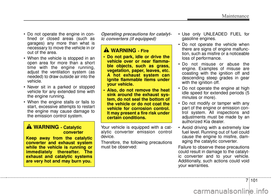
Do not operate the engine in con-fined or closed areas (such as
garages) any more than what is
necessary to move the vehicle in or
out of the area.
When the vehicle is stopped in an open area for more than a short
time with the engine running,
adjust the ventilation system (as
needed) to draw outside air into the
vehicle.
Never sit in a parked or stopped vehicle for any extended time with
the engine running.
When the engine stalls or fails to start, excessive attempts to restart
the engine may cause damage to
the emission control system.Operating precautions for catalyt-
ic converters (if equipped)
Your vehicle is equipped with a cat-
alytic converter emission control
device.
Therefore, the following precautions
must be observed: Use only UNLEADED FUEL for
gasoline engines.
Do not operate the vehicle when there are signs of engine malfunc-
tion, such as misfire or a noticeable
loss of performance.
Do not misuse or abuse the engine. Examples of misuse are
coasting with the ignition off and
descending steep grades in gear
with the ignition off.
Do not operate the engine at high idle speed for extended periods (5
minutes or more).
Do not modify or tamper with any part of the engine or emission con-
trol system. All inspections and
adjustments must be made by an
authorized Kia dealer.
Avoid driving with a extremely low fuel level. Running out of fuel could
cause the engine to misfire, dam-
aging the catalytic converter.
Failure to observe these precautions
could result in damage to the catalyt-
ic converter and to your vehicle.
Additionally, such actions could void
your warranties.
WARNING- Fire
Do not park, idle or drive the vehicle over or near flamma-
ble objects, such as grass,
vegetation, paper, leaves, etc.
A hot exhaust system can
ignite flammable items under
your vehicle.
Also, do not remove the heat sink around the exhaust sys-
tem, do not seal the bottom of
the vehicle or do not coat the
vehicle for corrosion control.
It may present a fire risk under
certain conditions.
WARNING- Catalytic
converter
Keep away from the catalytic
converter and exhaust system
while the vehicle is running or
immediately thereafter. The
exhaust and catalytic systems
are very hot and may burn you.
Page 474 of 487
68
Specifications & Consumer information
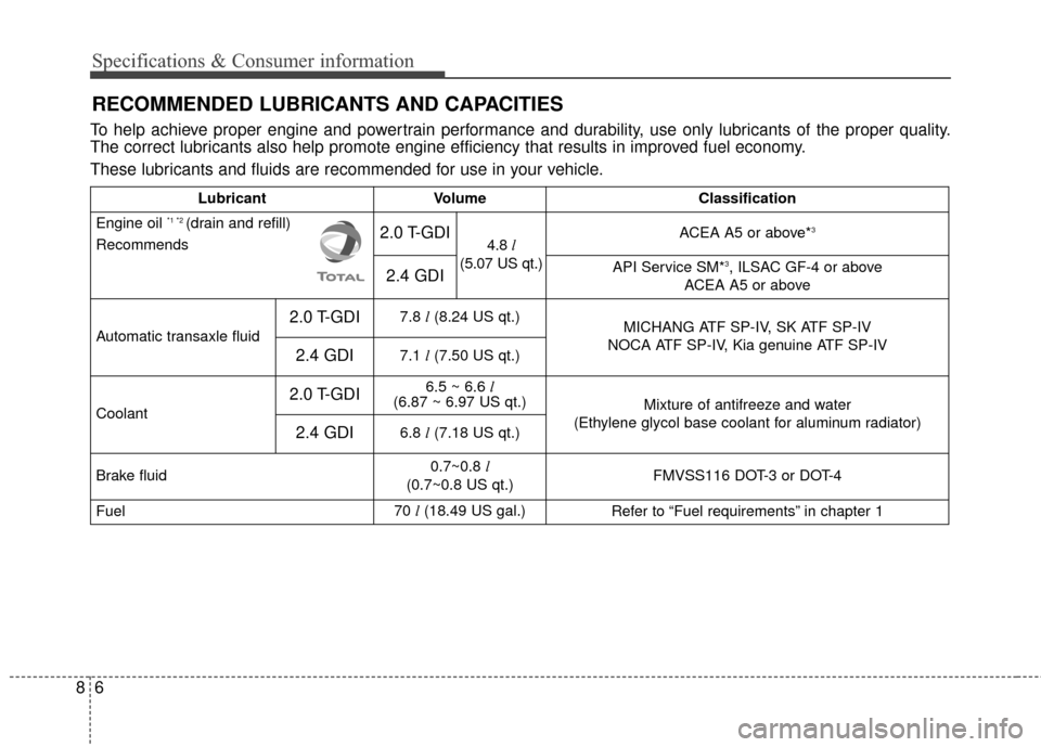
RECOMMENDED LUBRICANTS AND CAPACITIES
To help achieve proper engine and powertrain performance and durability, use only lubricants of the proper quality.
The correct lubricants also help promote engine efficiency that results in improved fuel economy.
These lubricants and fluids are recommended for use in your vehicle.
LubricantVolumeClassification
Engine oil *1 *2 (drain and refill)
Recommends2.0 T-GDI4.8 l
(5.07 US qt.)ACEA A5 or above*3
2.4 GDIAPI Service SM*3, ILSAC GF-4 or above
ACEA A5 or above
Automatic transaxle fluid
2.0 T-GDI7.8 l(8.24 US qt.)MICHANG ATF SP-IV, SK ATF SP-IV
NOCA ATF SP-IV, Kia genuine ATF SP-IV
2.4 GDI7.1 l(7.50 US qt.)
Coolant
2.0 T-GDI6.5 ~ 6.6 l
(6.87 ~ 6.97 US qt.)
Mixture of antifreeze and water
(Ethylene glycol base coolant for aluminum radiator)
2.4 GDI6.8 l(7.18 US qt.)
Brake fluid0.7~0.8 l
(0.7~0.8 US qt.)FMVSS116 DOT-3 or DOT-4
Fuel70 l(18.49 US gal.)Refer to “Fuel requirements” in chapter 1
Page 475 of 487
87
Specifications & Consumer information
*1Refer to the recommended SAE viscosity numbers on the next page.
*
2Engine oils labeled Energy Conserving Oil are now available. Along with other additional benefits, they contribute to fuel econ-
omy by reducing the amount of fuel necessary to overcome engine friction. Often, these improvements are difficult to measure
in everyday driving, but in a year’s time, they can offer significant cost and energy savings.
*
3API SL/ILSAC GF-3/ACEA A3 oil can be used if the recommended oil is not available.
Page 476 of 487
88
Specifications & Consumer information
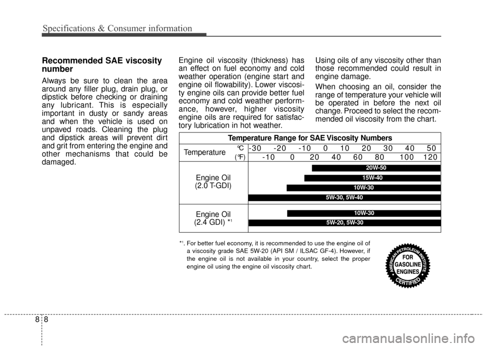
Recommended SAE viscosity
number
Always be sure to clean the area
around any filler plug, drain plug, or
dipstick before checking or draining
any lubricant. This is especially
important in dusty or sandy areas
and when the vehicle is used on
unpaved roads. Cleaning the plug
and dipstick areas will prevent dirt
and grit from entering the engine and
other mechanisms that could be
damaged.Engine oil viscosity (thickness) has
an effect on fuel economy and cold
weather operation (engine start and
engine oil flowability). Lower viscosi-
ty engine oils can provide better fuel
economy and cold weather perform-
ance, however, higher viscosity
engine oils are required for satisfac-
tory lubrication in hot weather.
Using oils of any viscosity other than
those recommended could result in
engine damage.
When choosing an oil, consider the
range of temperature your vehicle will
be operated in before the next oil
change. Proceed to select the recom-
mended oil viscosity from the chart.
Temperature Range for SAE Viscosity Numbers
Temperature
Engine Oil
(2.4 GDI) *
1
Engine Oil
(2.0 T-GDI)
°C
(°F)-30 -20 -10 0 10 20 30 40 50 -10 0 20 40 60 80 100 120
10W-30
5W-20, 5W-30
*1. For better fuel economy, it is recommended to use the engine oil of
a viscosity grade SAE 5W-20 (API SM / ILSAC GF-4). However, if
the engine oil is not available in your country, select the proper
engine oil using the engine oil viscosity chart.
20W-50
10W-30
15W-40
5W-30, 5W-40