tire pressure KIA OPTIMA 2020 Features and Functions Guide
[x] Cancel search | Manufacturer: KIA, Model Year: 2020, Model line: OPTIMA, Model: KIA OPTIMA 2020Pages: 591, PDF Size: 14.1 MB
Page 438 of 591

619
What to do in an emergency
Position the wrench as shown in the
drawing and tighten the wheel nuts.
Be sure the socket is seated com-
pletely over the nut. Do not stand on
the wrench handle or use an exten-
sion pipe over the wrench handle. Go
around the wheel, tightening every
nut following the numerical sequence
shown in the image until they are all
tight. Double-check each nut for
tightness. After changing wheels,
have an authorized Kia dealer tight-
en the wheel nuts to their proper
torque as soon as possible.
Wheel nut tightening torque:
79~94 lbf·ft (11~13 kgf·m)If you have a tire gauge, remove the
valve cap and check the air pressure.
If the pressure is lower than recom-
mended, drive slowly to the nearest
service station and inflate to the cor-
rect pressure. If it is too high, adjust
it until it is correct. Always reinstall
the valve cap after checking or
adjusting the tire pressure. If the cap
is not replaced, dust and dirt may get
into the tire valve and air may leak
from the tire. If you lose a valve cap,
buy another and install it as soon as
possible.
After you have changed the wheels,
always secure the flat tire in its place
and return the jack and tools to their
proper storage locations.
Note that most lug nuts do not have
metric threads. Be sure to use
extreme care in checking for thread
style before installing aftermarket lug
nuts or wheels. If in doubt, consult an
authorized Kia dealer.
CAUTION- Reusing lug
nuts
Make certain during wheelremoval that the same nuts thatwere removed are reinstalled -or, if replaced, that nuts withmetric threads and the samechamfer configuration are used.Your vehicle has metric threadson the wheel studs and nuts.Installation of a non-metricthread nut on a metric stud willnot secure the wheel to the hubproperly and will damage thestud so that it must be replaced.
OJF065009
JFa PE USA 6.qxp 5/15/2019 3:18 PM Page 19
Page 439 of 591
What to do in an emergency
20
6
To prevent the jack, wheel lug nut
wrench and spare tire from rattling
while the vehicle is in motion, store
them properly.
Check the inflation pressures as
soon as possible after installing the
spare tire. Adjust it to the specified
pressure, if necessary. Refer to
“Tires and wheels” in section 8.
Important - use of compact spare
tire
Your vehicle is equipped with a com-
pact spare tire. This compact spare
tire takes up less space than a regu-
lar-size tire. This tire is smaller than a
conventional tire and is designed for
temporary use only.
You should drive carefully when the compact spare is in use. The
compact spare should be replaced
by the proper conventional tire and
rim at the first opportunity.
The operation of this vehicle is not recommended with more than one
compact spare tire in use at the
same time. The compact spare should be inflat-
ed to 60 psi (420 kPa).
✽ ✽
NOTICE
Check the inflation pressure after
installing the spare tire. Adjust it to
the specified pressure, as necessary.
WARNING- Spare tire
The compact spare tire is for
emergency use only. Do not
operate your vehicle on this
compact spare at speeds over
50 mph (80 km/h). The original
tire should be repaired or
replaced as soon as possible to
avoid failure of the spare possi-
bly leading to personal injury or
death.WARNING- Wheel studs
If the studs are damaged, they
may lose their ability to retain
the wheel. This could lead to the
loss of the wheel and a collision
resulting in serious injuries.
JFa PE USA 6.qxp 5/15/2019 3:18 PM Page 20
Page 443 of 591
What to do in an emergency
24
6
Introduction
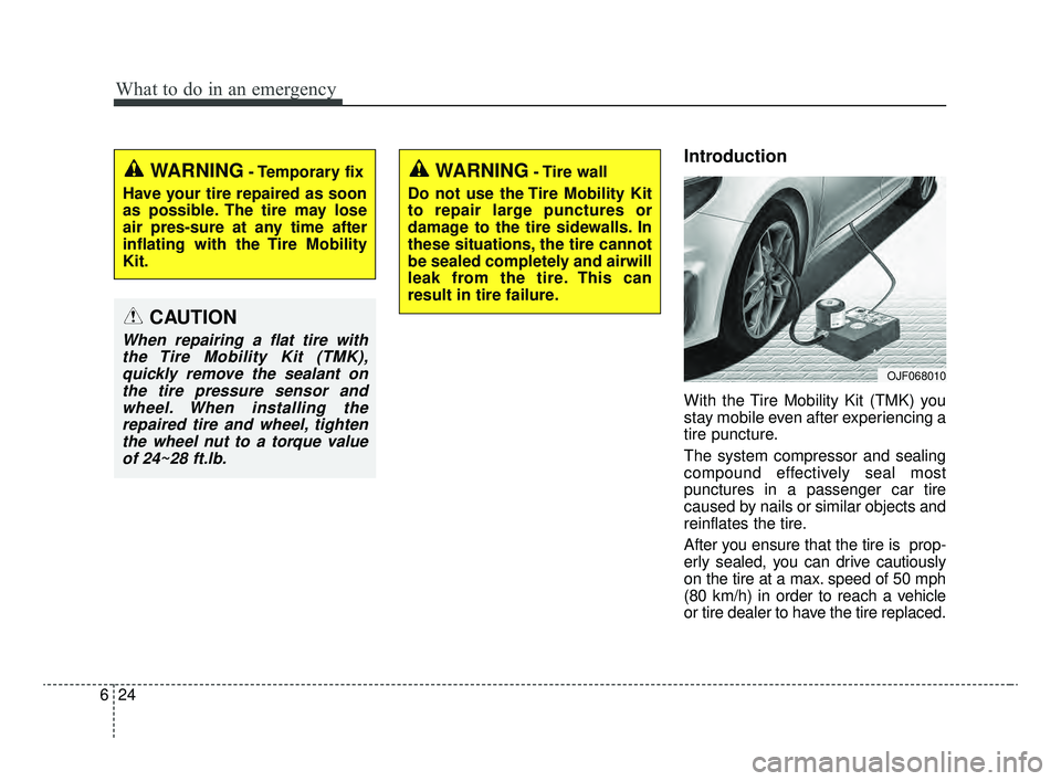
With the Tire Mobility Kit (TMK) you
stay mobile even after experiencing a
tire puncture.
The system compressor and sealing
compound effectively seal most
punctures in a passenger car tire
caused by nails or similar objects and
reinflates the tire.
After you ensure that the tire is prop-
erly sealed, you can drive cautiously
on the tire at a max. speed of 50 mph
(80 km/h) in order to reach a vehicle
or tire dealer to have the tire replaced.
WARNING- Temporary fix
Have your tire repaired as soon
as possible. The tire may lose
air pres-sure at any time after
inflating with the Tire Mobility
Kit.WARNING- Tire wall
Do not use the Tire Mobility Kit
to repair large punctures or
damage to the tire sidewalls. In
these situations, the tire cannot
be sealed completely and airwill
leak from the tire. This can
result in tire failure.
CAUTION
When repairing a flat tire with the Tire Mobility Kit (TMK),quickly remove the sealant onthe tire pressure sensor andwheel. When installing therepaired tire and wheel, tightenthe wheel nut to a torque valueof 24~28 ft.lb.
OJF068010
JFa PE USA 6.qxp 5/15/2019 3:18 PM Page 24
Page 444 of 591
625
What to do in an emergency
It is possible that some tires, espe-
cially with larger punctures or dam-
age to the sidewall, cannot be sealed
completely.
Air pressure loss in the tire may
adversely affect tire performance.
For this reason, you should avoid
abrupt steering or other driving
maneuvers, especially if the vehicle is
heavily loaded or if a trailer is in use.
The Tire Mobility Kit is not designed
or intended as a permanent tire
repair method and is to be used for
one tire only.
This instruction shows you step by
step how to temporarily seal the
puncture.
Read the section "Notes on the safe
use of the Tire Mobility Kit".Notes on the safe use of the
Tire Mobility Kit
Park your car at the side of theroad so that you can work with the
Tire Mobility Kit away from moving
traffic.
To be sure your vehicle will not move, even when you're on fairly
level ground, always set your park-
ing brake.
Only use the Tire Mobility Kit for sealing/inflation passenger car
tires. Only punctured areas located
within the tread region of the tire
can be sealed using the Tire
Mobility Kit.
Do not use on motorcycles, bicy- cles or any other type of tires.
When the tire and wheel are dam- aged, do not use Tire Mobility Kit
for your safety. Use of the Tire Mobility Kit may not
be effective for tire damage larger
than approximately 0.24 in (6 mm).
Please contact the nearest Kia
dealership if the tire cannot be
made roadworthy with the Tire
Mobility Kit.
Do not remove any foreign objects such as nails or screws that have
penetrated the tire.
Provided the car is outdoors, leave the engine running. Otherwise
operating the compressor may
eventually drain the car battery.
Never leave the Tire Mobility Kit unattended while it is being used.
Do not leave the compressor run- ning for more than 10 min. at a time
or it may overheat.
Do not use the Tire Mobility Kit if the ambient temperature is below -22°F
(-30°C).
JFa PE USA 6.qxp 5/15/2019 3:18 PM Page 25
Page 446 of 591
627
What to do in an emergency
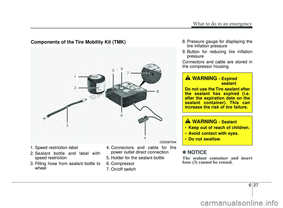
1. Speed restriction label
2. Sealant bottle and label withspeed restriction
3. Filling hose from sealant bottle to wheel 4. Connectors and cable for the
power outlet direct connection
5. Holder for the sealant bottle
6. Compressor
7. On/off switch 8. Pressure gauge for displaying the
tire inflation pressure
9. Button for reducing tire inflation pressure
Connectors and cable are stored in
the compressor housing.
✽ ✽ NOTICE
The sealant container and insert
hose (3) cannot be reused.
ODE067044
Components of the Tire Mobility Kit (TMK)
WARNING - Sealant
Keep out of reach of children.
Avoid contact with eyes.
Do not swallow.
WARNING - Expired sealant
Do not use the Tire sealant after
the sealant has expired (i.e.
after the expiration date on the
sealant container). This can
increase the risk of tire failure.
JFa PE USA 6.qxp 5/15/2019 3:18 PM Page 27
Page 447 of 591
What to do in an emergency
28
6
Using the Tire Mobility Kit
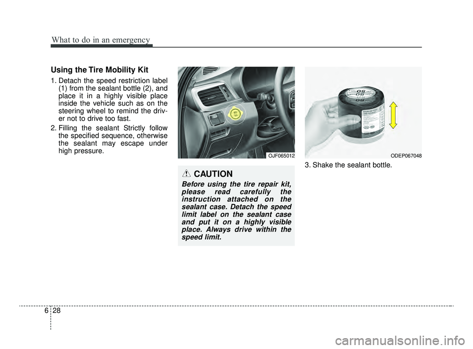
1. Detach the speed restriction label
(1) from the sealant bottle (2), and
place it in a highly visible place
inside the vehicle such as on the
steering wheel to remind the driv-
er not to drive too fast.
2. Filling the sealant Strictly follow the specified sequence, otherwise
the sealant may escape under
high pressure.
3. Shake the sealant bottle.
OJF065012ODEP067048
CAUTION
Before using the tire repair kit,please read carefully theinstruction attached on thesealant case. Detach the speedlimit label on the sealant caseand put it on a highly visibleplace. Always drive within thespeed limit.
JFa PE USA 6.qxp 5/15/2019 3:18 PM Page 28
Page 449 of 591
What to do in an emergency
30
6
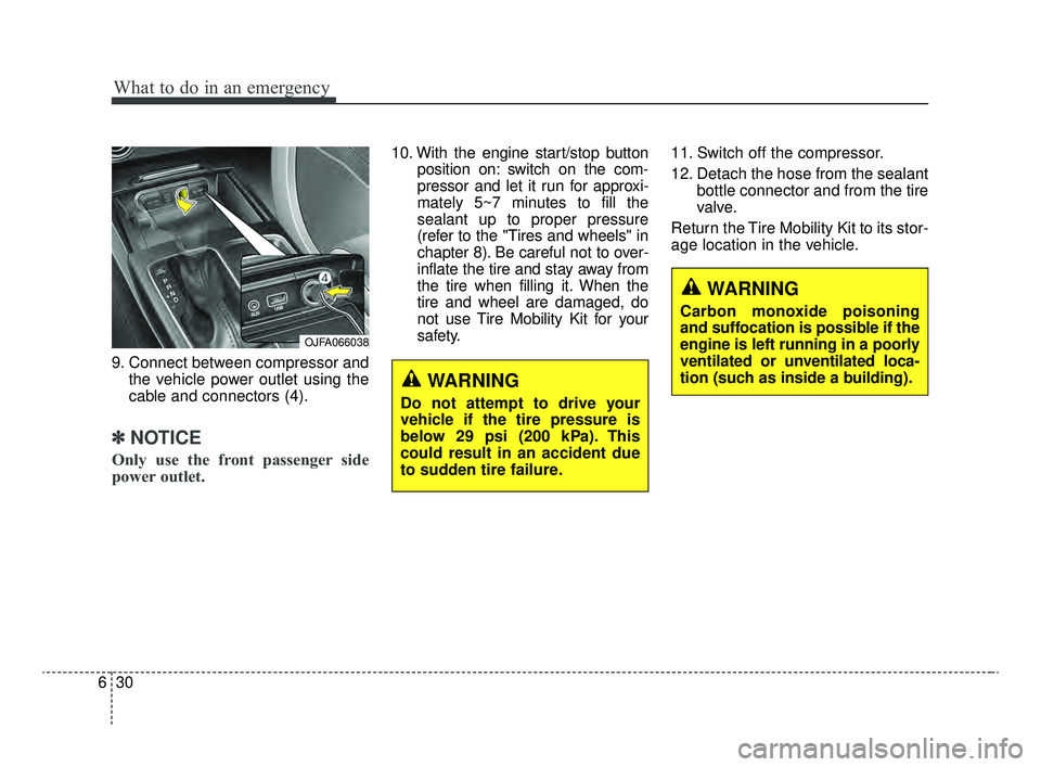
9. Connect between compressor and
the vehicle power outlet using the
cable and connectors (4).
✽ ✽NOTICE
Only use the front passenger side
power outlet.
10. With the engine start/stop button
position on: switch on the com-
pressor and let it run for approxi-
mately 5~7 minutes to fill the
sealant up to proper pressure
(refer to the "Tires and wheels" in
chapter 8). Be careful not to over-
inflate the tire and stay away from
the tire when filling it. When the
tire and wheel are damaged, do
not use Tire Mobility Kit for your
safety. 11. Switch off the compressor.
12. Detach the hose from the sealant
bottle connector and from the tire
valve.
Return the Tire Mobility Kit to its stor-
age location in the vehicle.
OJFA066038
WARNING
Do not attempt to drive your
vehicle if the tire pressure is
below 29 psi (200 kPa). This
could result in an accident due
to sudden tire failure.
WARNING
Carbon monoxide poisoning
and suffocation is possible if the
engine is left running in a poorly
ventilated or unventilated loca-
tion (such as inside a building).
JFa PE USA 6.qxp 5/15/2019 3:18 PM Page 30
Page 450 of 591
631
What to do in an emergency
Distributing the sealant
13. Immediately drive approximately4~6 miles (7~10 km or, about 10
min) to evenly distribute the
sealant in the tire.
When you use the Tire Mobility Kit,
the tire pressure sensors and wheel
may be stained by sealant. Therefore,
remove the tire pressure sensors and
wheel stained by sealant and have
your vehicle inspected by an author-
ized Kia dealer.
Checking the tire inflation
pressure
1.After driving approximately 4~6 miles (7~10 km or about 10 min-
utes), stop at a suitable location.
2.Connect the filling hose (3) of the compressor (clip mounted side)
directly and then connect the filling
hose (3) (opposite side) to the tire
valve.
3.Connect between compressor and the vehicle power outlet using the
cable and connectors.
4.Adjust the tire inflation pressure to 29 psi (200 kPa). With the ignition
switched on, proceed as follows.
- To increase the inflation pres-sure: Switch on the compressor,
position I. To check the current
inflation pressure setting, briefly
switch off the compressor. - To reduce the inflation pres-
sure: Press the button (9) on the
compressor.
CAUTION - Tire pressure
sensor
When you use the Tire MobilityKit including sealant notapproved by Kia, the tire pres-sure sensors may be damagedby sealant. The sealant on thetire pressure sensor and wheelshould be removed when youreplace the tire with a new oneand inspect the tire pressuresensors at an authorized dealer.
WARNING
Do not let the compressor run
for more than 10 minutes, other-
wise the device will overheat
and may be damaged.
JFa PE USA 6.qxp 5/15/2019 3:18 PM Page 31
Page 451 of 591

What to do in an emergency
32
6
Technical Data
System voltage: DC 12 V
Working voltage: DC 10 - 15 V
Amperage rating: max. 15 A ± 1A (at
DC 12V operation)
Suitable for use at temperatures: -22 ~ +158°F (-30 ~ +70°C)
Max. working pressure: 87 psi (6 bar)
Size
Compressor: 6.3 x 5.9 x 2.2 in. (161 x 150 x 55.8 mm)
Sealant bottle: 4.1 x 3.3 ø in. (104 x 85 ø mm)
Compressor weight: 1.77 lbs ± 0.07 lbs (805g ± 30g)
Sealant volume: 18.3 cu. in. (300 ml) ❈
Sealant and spare parts can be
obtained and replaced at an
authorized vehicle or tire dealer.
Empty sealant bottles may be dis-
posed of at home. Liquid residue
from the sealant should be dis-
posed of by your vehicle or tire
dealer or in accordance with local
waste disposal regulations.
JFa PE USA 6.qxp 5/15/2019 3:18 PM Page 32
Page 455 of 591

Climate control air filter . . . . . . . . . . . . . . . . . . . . 7-36
• Filter inspection . . . . . . . . . . . . . . . . . . . . . . . . . . . . . . 7-36
Wiper blades . . . . . . . . . . . . . . . . . . . . . . . . . . . . . . 7-38
• Blade inspection . . . . . . . . . . . . . . . . . . . . . . . . . . . . . . 7-38
• Blade replacement . . . . . . . . . . . . . . . . . . . . . . . . . . . . 7-38
Battery . . . . . . . . . . . . . . . . . . . . . . . . . . . . . . . . . . . 7-\
42
• For best battery service . . . . . . . . . . . . . . . . . . . . . . . 7-42
• Recharging the battery . . . . . . . . . . . . . . . . . . . . . . . . 7-43
• Reset items . . . . . . . . . . . . . . . . . . . . . . . . . . . . . . . . . . 7-44\
Tires and wheels . . . . . . . . . . . . . . . . . . . . . . . . . . . 7-45
• Tire care . . . . . . . . . . . . . . . . . . . . . . . . . . . . . . . . . . . . \
7-45
• Recommended cold tire inflation pressures . . . . . . . 7-45
• Tire pressure . . . . . . . . . . . . . . . . . . . . . . . . . . . . . . . . 7-46
• Checking tire inflation pressure. . . . . . . . . . . . . . . . . 7-46
• Tire rotation . . . . . . . . . . . . . . . . . . . . . . . . . . . . . . . . . 7-47
• Wheel alignment and tire balance . . . . . . . . . . . . . . . 7-48
• Tire replacement . . . . . . . . . . . . . . . . . . . . . . . . . . . . . 7-49
• Wheel replacement . . . . . . . . . . . . . . . . . . . . . . . . . . . 7-50
• Tire traction . . . . . . . . . . . . . . . . . . . . . . . . . . . . . . . . . 7-50
• Tire maintenance . . . . . . . . . . . . . . . . . . . . . . . . . . . . . 7-50
• Tire sidewall labeling . . . . . . . . . . . . . . . . . . . . . . . . . 7-50
• All season tires . . . . . . . . . . . . . . . . . . . . . . . . . . . . . . . 7-57
• Summer tires . . . . . . . . . . . . . . . . . . . . . . . . . . . . . . . . 7-57
• Snow tires . . . . . . . . . . . . . . . . . . . . . . . . . . . . . . . . . . . 7-\
57
• Tire chains . . . . . . . . . . . . . . . . . . . . . . . . . . . . . . . . . . 7-58\
• Radial-ply tires . . . . . . . . . . . . . . . . . . . . . . . . . . . . . . 7-58
• Low aspect ratio tire . . . . . . . . . . . . . . . . . . . . . . . . . . 7-59
Fuses . . . . . . . . . . . . . . . . . . . . . . . . . . . . . . . . . . . . \
7-60
• Inner panel fuse replacement . . . . . . . . . . . . . . . . . . . 7-62
• Engine compartment fuse replacement. . . . . . . . . . . 7-64
• Fuse/relay panel description. . . . . . . . . . . . . . . . . . . . 7-66
Light bulbs . . . . . . . . . . . . . . . . . . . . . . . . . . . . . . . 7-76
• Bulb replacement precaution . . . . . . . . . . . . . . . . . . . 7-76
• Light bulb position (Front). . . . . . . . . . . . . . . . . . . . . 7-78
• Light bulb position (Rear) . . . . . . . . . . . . . . . . . . . . . 7-79
• Light bulb position (Side) . . . . . . . . . . . . . . . . . . . . . . 7-80
• Headlamp (Low beam) bulb replacement
(Headlamp Type A) . . . . . . . . . . . . . . . . . . . . . . . . . . 7-80
• Headlamp (High beam) bulb replacement (Headlamp Type A) . . . . . . . . . . . . . . . . . . . . . . . . . . 7-81
• Front turn signal lamp bulb replacement (Headlamp Type A) . . . . . . . . . . . . . . . . . . . . . . . . . . 7-82
• Headlamp (Low/High beam) (LED type) bulb replacement (Headlamp Type B) . . . . . . . . . . 7-82
• Position lamp / Day time running lamp (LED type) replacement (Headlamp Type A, B) . . . . . . . . . . . . 7-83
• Front fog lamp bulb replacement . . . . . . . . . . . . . . . 7-83
• Side repeater lamp (LED type) bulb replacement . . 7-84
• Rear turn signal lamp bulb replacement . . . . . . . . . 7-84
• Stop and tail lamp bulb replacement . . . . . . . . . . . . 7-85
7
JFa PE USA 7.qxp 5/15/2019 3:12 PM Page 2