tow KIA Rio 2005 2.G User Guide
[x] Cancel search | Manufacturer: KIA, Model Year: 2005, Model line: Rio, Model: KIA Rio 2005 2.GPages: 238, PDF Size: 2.6 MB
Page 84 of 238
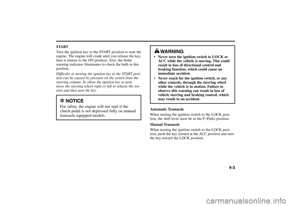
START
Turn the ignition key to the START position to start the
engine. The engine will crank until you release the key,
then it returns to the ON position. Also, the brake
warning indicator illuminates to check the bulb in this
position.
Difficulty in turning the ignition key to the START posi-
tion can be caused by pressure on the switch from the
steering column. To allow the ignition key to turn,
move the steering wheel right or left to release the ten-
sion and then turn the key.
Automatic Transaxle
When turning the ignition switch to the LOCK posi-
tion, the shift lever must be in the P (Park) position.
Manual Transaxle
When turning the ignition switch to the LOCK posi-
tion, push the key inward at the ACC position and turn
the key toward the LOCK position.
4-3
WARNING
• Never turn the ignition switch to LOCK or
ACC while the vehicle is moving. This could
result in loss of directional control and
braking function, which could cause an
immediate accident.
Never reach for the ignition switch, or any
other controls, through the steering wheel
while the vehicle is in motion. Failure to
observe this warning can result in loss of
vehicle steering and braking control, which
may result in an accident.
✽
NOTICE
For safety, the engine will not start if the
clutch pedal is not depressed fully on manual
transaxle equipped models.
RIO ENG CNA 4.qxd 7/29/05 5:06 PM Page 3
Page 102 of 238
Parking on Curbed Streets When parking your vehicle on an uphill grade, park
as close to the curb as possible and turn the front
wheels away from the curb so that the front wheels
will contact the curb if the vehicle moves backward.
When parking your vehicle on a downhill grade,
park as close to the curb as possible and turn the
front wheels toward the curb so that the front wheels
will contact the curb if the vehicle moves forward.
4-21
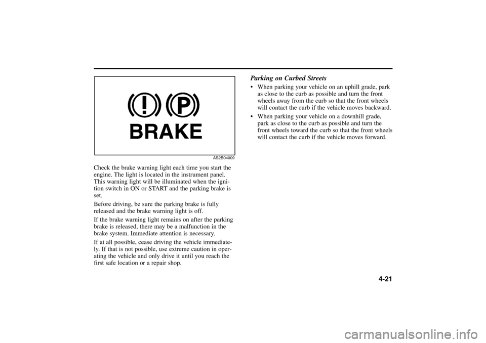
Check the brake warning light each time you start the
engine. The light is located in the instrument panel.
This warning light will be illuminated when the igni-
tion switch in ON or START and the parking brake is
set.
Before driving, be sure the parking brake is fully
released and the brake warning light is off.
If the brake warning light remains on after the parking
brake is released, there may be a malfunction in the
brake system. Immediate attention is necessary.
If at all possible, cease driving the vehicle immediate-
ly. If that is not possible, use extreme caution in oper-
ating the vehicle and only drive it until you reach the
first safe location or a repair shop.
AS2B04009
RIO ENG CNA 4.qxd 7/29/05 5:06 PM Page 21
Page 107 of 238
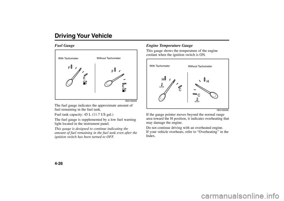
Driving Your Vehicle4-26 Fuel GaugeThe fuel gauge indicates the approximate amount of
fuel remaining in the fuel tank.
Fuel tank capacity: 45 L (11.7 US gal.)
The fuel gauge is supplemented by a low fuel warning
light located in the instrument panel.
This gauge is designed to continue indicating the
amount of fuel remaining in the fuel tank even after the
ignition switch has been turned to OFF.
Engine Temperature GaugeThis gauge shows the temperature of the engine
coolant when the ignition switch is ON.
If the gauge pointer moves beyond the normal range
area toward the H position, it indicates overheating that
may damage the engine.
Do not continue driving with an overheated engine.
If your vehicle overheats, refer to “Overheating’’ in the
Index.
1B3105005
1B3105006
With Tachometer
Without Tachometer
With Tachometer
Without Tachometer
RIO ENG CNA 4.qxd 7/29/05 5:06 PM Page 26
Page 109 of 238
Driving Your Vehicle4-28Low Brake Fluid Level Warning
If the warning light remains ON when the parking
brake is released, it may indicate that the brake fluid
level in the reservoir is low.
If the warning light remains ON:
1. Drive to the nearest safe location and carefully stop
your vehicle.
2. With the engine stopped, check the brake fluid level
immediately and add fluid as required. All brake
components should also be checked immediately
for fluid leaks.
3. If leaks are found, if the warning light remains ON,
or if the brakes do not operate properly, do not
drive the vehicle. Have it towed to an Authorized
Kia Dealer for a brake system inspection and nec-
essary repairs.To check bulb operation, the warning light illuminates
when the ignition switch is in the ON position.
Safety Belt Warning As a reminder to the driver and passenger, safety belt
warning light will illuminate for approximately 6 sec-
onds each time you turn the ignition switch ON.
If the driver’s lap/shoulder belt is not fastened when
the key is turned ON, a chime sounds for approximate-
ly six seconds and the safety belt warning light illumi-
nates for approximately six seconds. If the system does
not operate as described, see an Authorized Kia Dealer
for assistance.Air Bag Warning This warning light will remain ON for approximately
6 seconds each time you turn the ignition switch ON.
If the system does not operate as described or if the
light comes on while the vehicle is being driven, see an
Authorized Kia Dealer for immediate assistance.Charging System Warning This warning light indicates a malfunction of either the
generator or electrical charging system.
–
+
WARNING - Brake Warning
Lights
Driving the vehicle with a warning light ON is
dangerous. If the brake warning light remains
ON, have the brakes checked and repaired
immediately.
RIO ENG CNA 4.qxd 7/29/05 5:06 PM Page 28
Page 115 of 238
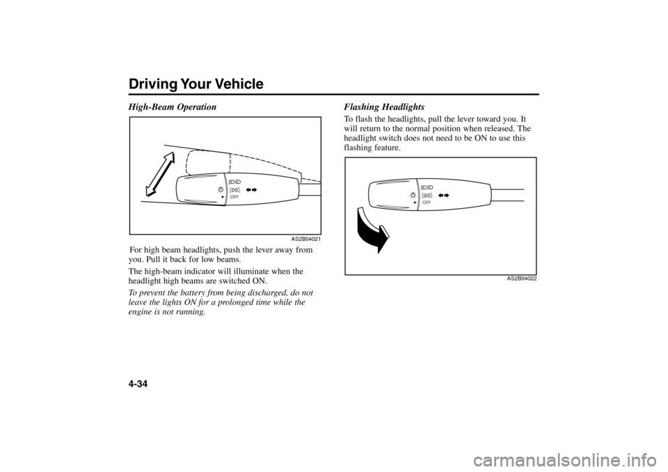
Driving Your Vehicle4-34 High-Beam OperationFor high beam headlights, push the lever away from
you. Pull it back for low beams.
The high-beam indicator will illuminate when the
headlight high beams are switched ON.
To prevent the battery from being discharged, do not
leave the lights ON for a prolonged time while the
engine is not running.
Flashing HeadlightsTo flash the headlights, pull the lever toward you. It
will return to the normal position when released. The
headlight switch does not need to be ON to use this
flashing feature.
AS2B04021
AS2B04022
RIO ENG CNA 4.qxd 7/29/05 5:06 PM Page 34
Page 118 of 238
4-37 Windshield Washers
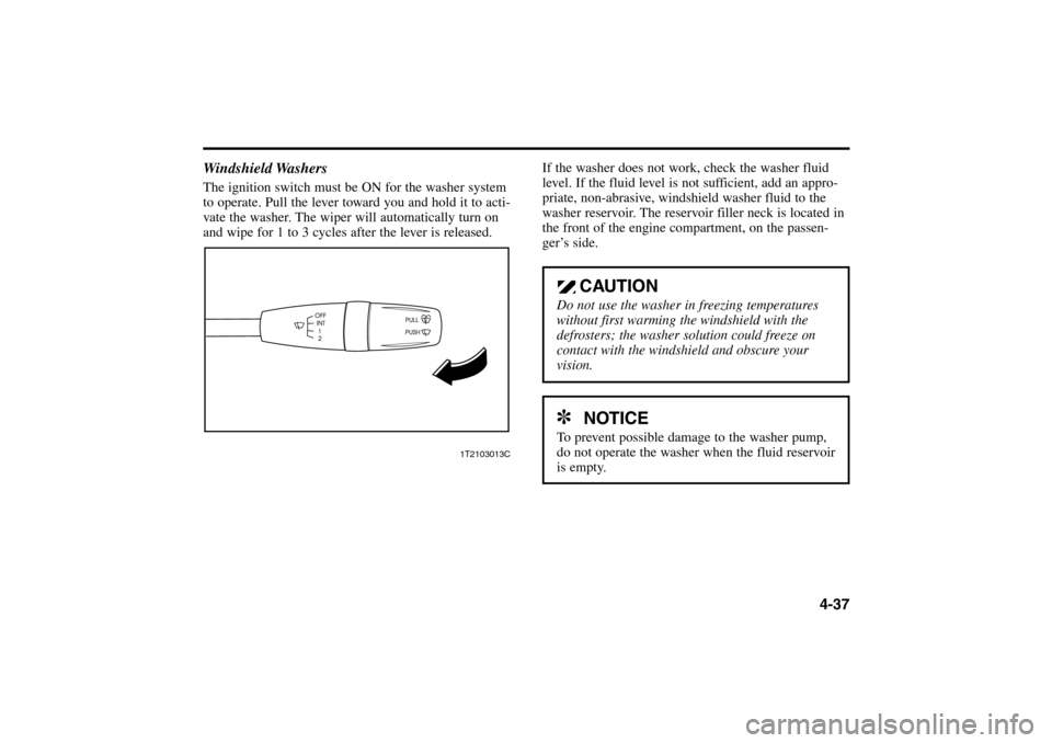
The ignition switch must be ON for the washer system
to operate. Pull the lever toward you and hold it to acti-
vate the washer. The wiper will automatically turn on
and wipe for 1 to 3 cycles after the lever is released.
1T2103013C
If the washer does not work, check the washer fluid
level. If the fluid level is not sufficient, add an appro-
priate, non-abrasive, windshield washer fluid to the
washer reservoir. The reservoir filler neck is located in
the front of the engine compartment, on the passen-
ger’s side.
CAUTION
Do not use the washer in freezing temperatures
without first warming the windshield with the
defrosters; the washer solution could freeze on
contact with the windshield and obscure your
vision.✽
NOTICE
To prevent possible damage to the washer pump,
do not operate the washer when the fluid reservoir
is empty.
RIO ENG CNA 4.qxd 7/29/05 5:06 PM Page 37
Page 123 of 238
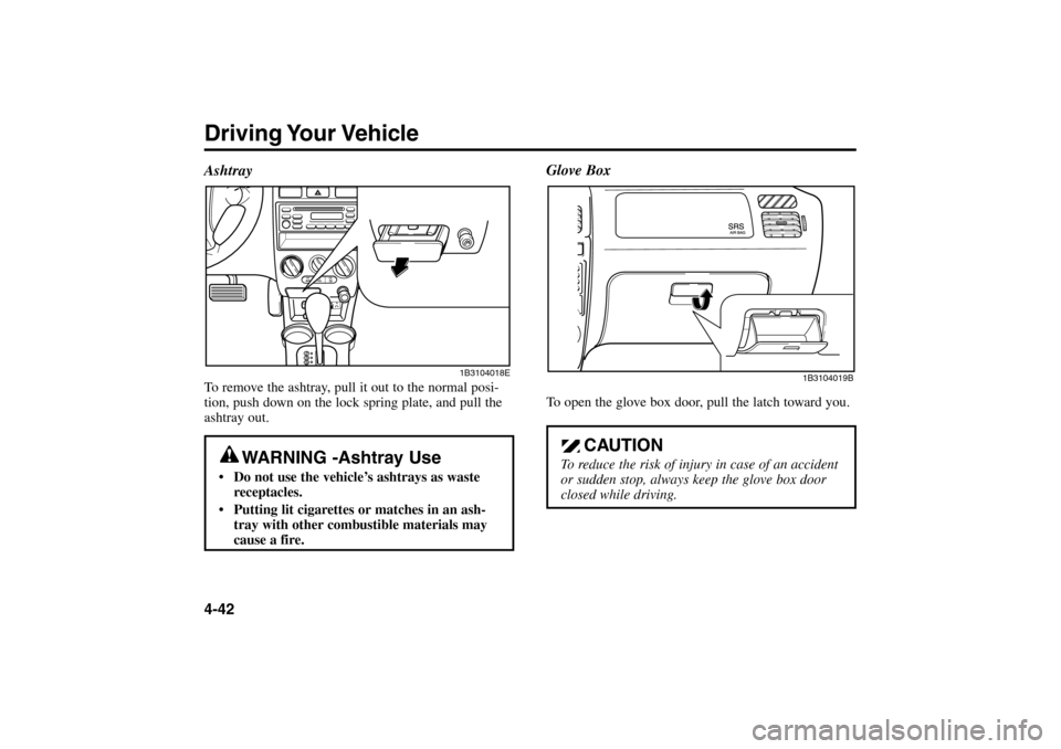
Driving Your Vehicle4-42Glove Box
To open the glove box door, pull the latch toward you.
CAUTION
To reduce the risk of injury in case of an accident
or sudden stop, always keep the glove box door
closed while driving.
1B3104019B
AshtrayTo remove the ashtray, pull it out to the normal posi-
tion, push down on the lock spring plate, and pull the
ashtray out.
WARNING -Ashtray Use
Do not use the vehicle’s ashtrays as waste
receptacles.
Putting lit cigarettes or matches in an ash-
tray with other combustible materials may
cause a fire.
1B3104018E
RIO ENG CNA 4.qxd 7/29/05 5:06 PM Page 42
Page 126 of 238
4-45
Fan Speed Control Knob
The fan speed control knob (B) is the center knob in the
climate control panel. Four (4) adjustable fan speeds are
provided;fan speed increases as the number on the knob
increases. The ignition switch must be in the ON
position for fan operation.
OFF – Fan off
1 – Low speed
2 – Medium speed
3 – High speed
4 – Maximum speed
Mode Selection Knob
The mode selection knob (C) is the closest to the
passenger’s seat in the climate control panel. It controls
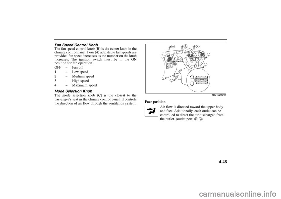
the direction of air flow through the ventilation system.Face position
Air flow is directed toward the upper body
and face. Additionally, each outlet can be
controlled to direct the air discharged from
the outlet. (outlet port: , )
1BC102004H
A
A
A
D
D
C
C
B
BB
D
RIO ENG CNA 4.qxd 7/29/05 5:06 PM Page 45
Page 127 of 238
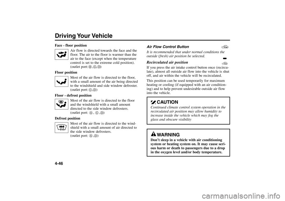
Driving Your Vehicle4-46Face - floor position
Air flow is directed towards the face and the
floor. The air to the floor is warmer than the
air to the face (except when the temperature
control is set to the extreme cold position).
(outlet port: , , )
Floor position
Most of the air flow is directed to the floor,
with a small amount of the air being directed
to the windshield and side window defroster.
(outlet port: , )
Floor - defrost position
Most of the air flow is directed to the floor
and the windshield with a small amount
directed to the side window defrosters.
(outlet port: , , )
Defrost position
Most of the air flow is directed to the wind-
shield with a small amount of air directed to
the side window defrosters.
(outlet port: , )Air Flow Control Button
It is recommended that under normal conditions the
outside (fresh) air position be selected.
Recirculated air position If you press the air intake control button once (recircu-
late), almost all outside air flow into the vehicle is shut
off, and air within the vehicle will be recirculated.
This position can be used temporarily for maximum
heating or cooling (if equipped with an air condition-
ing) and to help prevent undesirable outside air flow
into the vehicle.
BC
C
D
D
A
C
D
A
D
CAUTION
Continued climate control system operation in the
recirculated air position may allow humidity to
increase inside the vehicle which may fog the
glass and obscure visibility
WARNING
Don’t sleep in a vehicle with air conditioning
system or heating system on. It may cause seri-
ous harm or death to passengers due to a drop
in the oxygen level and/or body temperature.
RIO ENG CNA 4.qxd 7/29/05 5:06 PM Page 46
Page 135 of 238
5-1
DRIVING TIPSFuel Requirements . . . . . . . . . . . . . . . . . . . . . . . . . . . .5-2
Emission Control System . . . . . . . . . . . . . . . . . . . . . . .5-3
Before Driving . . . . . . . . . . . . . . . . . . . . . . . . . . . . . . . .5-4
Suggestions for Economical Operation . . . . . . . . . . . .5-6
Special Driving Conditions . . . . . . . . . . . . . . . . . . . . . .5-7
Trailer Towing . . . . . . . . . . . . . . . . . . . . . . . . . . . . . . .5-12
Overloading . . . . . . . . . . . . . . . . . . . . . . . . . . . . . . . .5-13
Label Information . . . . . . . . . . . . . . . . . . . . . . . . . . . .5-13
5
RIO ENG CNA 5.qxd 7/29/05 5:07 PM Page 1