battery capacity KIA RIO 2022 Owners Manual
[x] Cancel search | Manufacturer: KIA, Model Year: 2022, Model line: RIO, Model: KIA RIO 2022Pages: 528, PDF Size: 11.8 MB
Page 223 of 528

Features of your vehicle
144
4
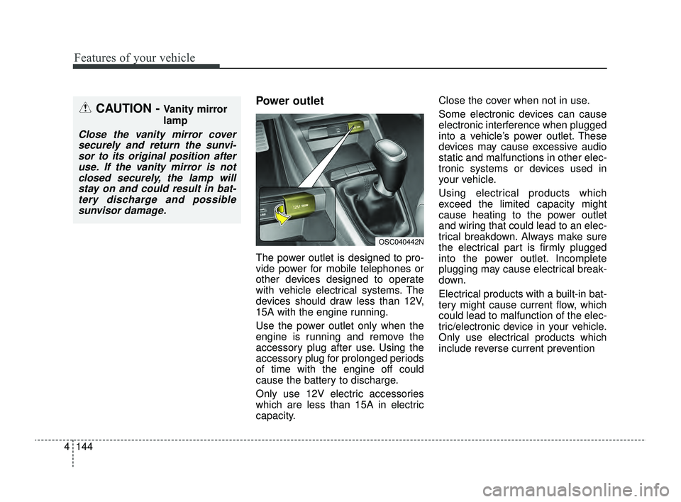
Power outlet
The power outlet is designed to pro-
vide power for mobile telephones or
other devices designed to operate
with vehicle electrical systems. The
devices should draw less than 12V,
15A with the engine running.
Use the power outlet only when the
engine is running and remove the
accessory plug after use. Using the
accessory plug for prolonged periods
of time with the engine off could
cause the battery to discharge.
Only use 12V electric accessories
which are less than 15A in electric
capacity. Close the cover when not in use.
Some electronic devices can cause
electronic interference when plugged
into a vehicle’s power outlet. These
devices may cause excessive audio
static and malfunctions in other elec-
tronic systems or devices used in
your vehicle.
Using electrical products which
exceed the limited capacity might
cause heating to the power outlet
and wiring that could lead to an elec-
trical breakdown. Always make sure
the electrical part is firmly plugged
into the power outlet. Incomplete
plugging may cause electrical break-
down.
Electrical products with a built-in bat-
tery might cause current flow, which
could lead to malfunction of the elec-
tric/electronic device in your vehicle.
Only use electrical products which
include reverse current prevention
CAUTION - Vanity mirror
lamp
Close the vanity mirror cover
securely and return the sunvi-sor to its original position afteruse. If the vanity mirror is notclosed securely, the lamp willstay on and could result in bat-tery discharge and possiblesunvisor damage.
OSC040442N
SC PE USA 4.QXP 9/9/2021 6:09 PM Page 144
Page 440 of 528

753
Maintenance
Production options weight:The
combined weight of installed regular
production options weighing over 5
lb.(2.3 kg) in excess of the standard
items which they replace, not previ-
ously considered in curb weight or
accessory weight, including heavy
duty brakes, ride levelers, roof rack,
heavy duty battery, and special trim.
Recommended Inflation Pressure:
Vehicle manufacturer's recommend-
ed tire inflation pressure as shown
on the tire placard.
Radial Ply Tire: A pneumatic tire in
which the ply cords that extend to the
beads are laid at 90 degrees to the
centerline of the tread.
Rim: A metal support for a tire and
upon which the tire beads are seat-
ed.
Sidewall: The portion of a tire
between the tread and the bead. Speed Rating:
An alphanumeric
code assigned to a tire indicating the
maximum speed at which a tire can
operate.
Traction: The friction between the
tire and the road surface. The
amount of grip provided.
Tread: The portion of a tire that
comes into contact with the road.
Treadwear Indicators: Narrow
bands, sometimes called "wear
bars," that show across the tread of a
tire when only 1/16 inch of tread
remains.
UTQGS: Uniform Tire Quality
Grading Standards, a tire information
system that provides consumers with
ratings for a tire's traction, tempera-
ture and treadwear. Ratings are
determined by tire manufacturers
using government testing proce-
dures. The ratings are molded into
the sidewall of the tire.
Vehicle Capacity Weight: The num-
ber of designated seating positions
multiplied by 150 lbs. (68kg) plus the
rated cargo and luggage load. Vehicle Maximum Load on the
Tire:
Load on an individual tire due
to curb and accessory weight plus
maximum occupant and cargo
weight.
Vehicle Normal Load on the Tire:
Load on an individual tire that is
determined by distributing to each
axle its share of the curb weight,
accessory weight, and normal occu-
pant weight and dividing by 2.
Vehicle Placard: A label permanent-
ly attached to a vehicle showing the
original equipment tire size and rec-
ommended inflation pressure.
SC PE USA 7.qxp 9/9/2021 6:27 PM Page 53
Page 444 of 528

757
Maintenance
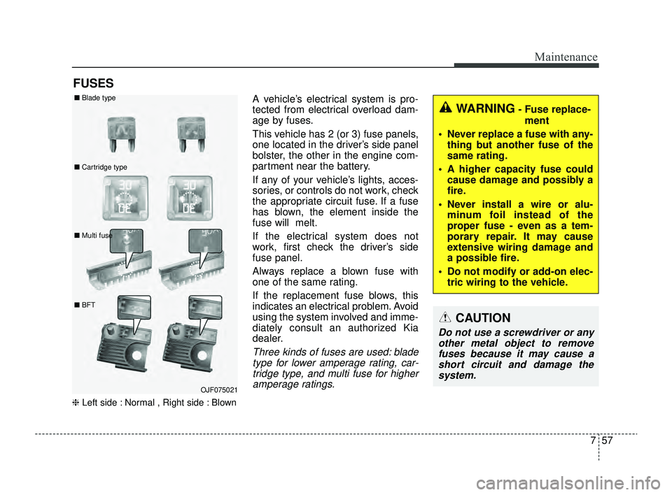
FUSES
❈Left side : Normal , Right side : Blown
A vehicle’s electrical system is pro-
tected from electrical overload dam-
age by fuses.
This vehicle has 2 (or 3) fuse panels,
one located in the driver’s side panel
bolster, the other in the engine com-
partment near the battery.
If any of your vehicle’s lights, acces-
sories, or controls do not work, check
the appropriate circuit fuse. If a fuse
has blown, the element inside the
fuse will melt.
If the electrical system does not
work, first check the driver’s side
fuse panel.
Always replace a blown fuse with
one of the same rating.
If the replacement fuse blows, this
indicates an electrical problem. Avoid
using the system involved and imme-
diately consult an authorized Kia
dealer.
Three kinds of fuses are used: blade
type for lower amperage rating, car-tridge type, and multi fuse for higheramperage ratings.
WARNING- Fuse replace-
ment
Never replace a fuse with any- thing but another fuse of the
same rating.
A higher capacity fuse could cause damage and possibly a
fire.
Never install a wire or alu- minum foil instead of the
proper fuse - even as a tem-
porary repair. It may cause
extensive wiring damage and
a possible fire.
Do not modify or add-on elec- tric wiring to the vehicle.
CAUTION
Do not use a screwdriver or anyother metal object to removefuses because it may cause ashort circuit and damage thesystem.
OJF075021
■
Blade type
■ Cartridge type
■ Multi fuse
■ BFT
SC PE USA 7.qxp 9/9/2021 6:27 PM Page 57
Page 445 of 528

Maintenance
58
7
✽ ✽
NOTICE
• When replacing fuse, turn the
ignition “OFF” and turn off
switches of all electrical devices
then remove battery (-) terminal.
• The actual fuse/relay panel label may differ from equipped items.
WARNING- Electrical Fire
Always ensure replacements
fuses and relays are securely
fastened when installed. Failure
to do so can result in a vehicle
fire.
CAUTION
When replacing a blown fuse or relay, make sure the newfuse or relay fits tightly intothe clips. Failure to tightlyinstall the fuse or relay maycause damage to the wiringand electric systems.
Do not remove fuses, relays and terminals fastened withbolts or nuts. The fuses, relaysand terminals may not be fas-tened correctly which maycause vehicle damage.
CAUTION
Do not input any other objects except fuses or relays intofuse/relay terminals such as ascrewdriver or wiring. It maycause contact failure and sys-tem malfunction.
Do not plug in screwdrivers or aftermarket wiring into the ter-minal originally designed forfuse and relays only. The elec-trical system and wiring of thevehicle interior may be dam-aged or burned due to contactfailure.
If you directly connect the wire on the taillight or replacethe bulb which is over the reg-ulated capacity to install trail-ers etc., the inner junctionblock can get burned.
SC PE USA 7.qxp 9/9/2021 6:27 PM Page 58