sensor KIA RIO HATCHBACK 2016 Owner's Manual
[x] Cancel search | Manufacturer: KIA, Model Year: 2016, Model line: RIO HATCHBACK, Model: KIA RIO HATCHBACK 2016Pages: 477, PDF Size: 13.46 MB
Page 339 of 477
What to do in an emergency
28
6
Technical Data
System voltage: DC 12 V
Working voltage: DC 10 - 15 V
Amperage rating: max. 15 A
Suitable for use at temperatures:
-22 ~ +158°F (-30 ~ +70°C)
Max. working pressure: 87 psi (6 bar)
Size
Compressor: 6.7 x 5.9 x 2.4 in. (170 x 150 x 60 mm)
Sealant bottle: 3.3 x 3.0 ø in. (85 x 77 ø mm)
Compressor weight: 1.8 lbs (0.8 kg)
Sealant volume: 12.2 cu. in. (200 ml)CAUTION - Tire pressuresensor
When you use the Tire Mobility
Kit including sealant notapproved by Kia, the tire pres-sure sensors may be damagedby sealant. The sealant on thetire pressure sensor and wheelshould be removed when youreplace the tire with a new oneand inspect the tire pressuresensors in authorized dealer.
Page 345 of 477
What to do in an emergency
34
6
9. Switch off the compressor.
10. Detach the hoses from the
sealant bottle connector and
from the tire valve.
Return the Tire Mobility Kit to its stor-
age location in the vehicle.
Distributing the sealant
Immediately drive approximately
4~6miles (7~10km or, about 10min)
to evenly distribute the sealant in the
tire.
Do not exceed a speed of 50 mph
(80 km/h). If possible, do not fall
below a speed of 12 mph (20 km/h).
While driving, if you experience any
unusual vibration, ride disturbance or
noise, reduce your speed and drive
with caution until you can safely pull
off of the side of the road.
Call for road side service or towing.
When you use the Tire Mobility Kit,
the tire pressure sensors and wheel
may be stained by sensors.
Therefore, remove the tire pressure
sensors and wheel stained by
sealant and have it serviced by an
authorized Kia dealer.
Checking the tire inflation
pressure
1. After driving approximately 4 ~ 6 miles (7 ~ 10 km or about 10min),
stop at a safe location.
2. Connect the filling hose (2) of the compressor (clip mounted side)
directly and then connect the fill-
ing hose (2) (opposite side) to the
tire valve.
3. Connect between compressor and the vehicle power outlet using the
cable and connectors.
4. Adjust the tire inflation pressure to the recomended tire inflation.
With the ignition swithched on, proceed as follows.
- To increase the inflation pres- sure : Switch on the compres-
sor, position I. To check the cur-
rent inflation pressure setting,
briefly switch off the compressor.
CAUTION - Tire pressure
Do not attempt to drive your vehicle if the tire pressure isbelow 230 kpa (33 PSI). Thiscould result in an accident dueto sudden tire failure.
WARNING- Carbon
monoxide
Do not leave your vehicle run-
ning in a poorly ventilated area
for extended periods of time.
Carbon monoxide poisoning
and suffocation can occur.
Page 346 of 477
635
What to do in an emergency
✽
✽NOTICE
The pressure gauge may show high-
er than actual reading when the
compressor is running. To get an
accurate tire pressure, the compres-
sor needs to be turned off.
- To reduce the inflation pres-
sure: Press the button (8) on the
compressor hose.
Technical Data
System voltage: DC 12 V
Working voltage: DC 10 - 15 V
Amperage rating: max. 10 A ± 1A
(at DC 12V operation)
Suitable for use at temperatures: -22 ~ +158°F (-30 ~ +70°C)
Max. working pressure: 6 bar (87 psi)
Size
Compressor: 6.3 x 5.9 x 2.2 in. (161 x 150 x 55.8 mm)
Sealant bottle: ø 3.3 x 3.2 in. (ø 85 x 81 mm)
Compressor weight: 1.62 lbs ± 0.06 lbs (735 g ± 25 g)
Sealant volume: 12.2 cu. in. (200 ml)CAUTION - Tire pressuresensor
When you use the Tire MobilityKit including sealant notapproved by Kia, the tire pres-sure sensors may be damagedby sealant. The sealant on thetire pressure sensor and wheelshould be removed when youreplace the tire with a new oneand inspect the tire pressuresensors in authorized dealer.
Page 392 of 477
Maintenance
42
7
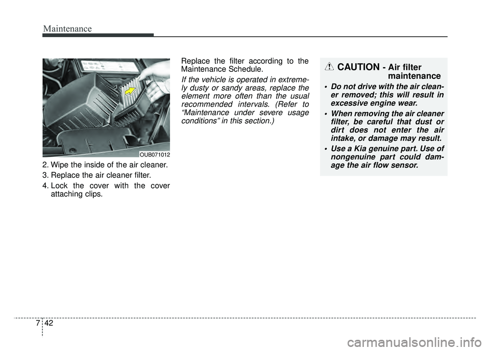
2. Wipe the inside of the air cleaner.
3. Replace the air cleaner filter.
4. Lock the cover with the cover
attaching clips. Replace the filter according to the
Maintenance Schedule.
If the vehicle is operated in extreme-
ly dusty or sandy areas, replace theelement more often than the usualrecommended intervals. (Refer to“Maintenance under severe usageconditions” in this section.)
CAUTION - Air filter maintenance
Do not drive with the air clean-
er removed; this will result inexcessive engine wear.
When removing the air cleaner filter, be careful that dust ordirt does not enter the airintake, or damage may result.
Use a Kia genuine part. Use of nongenuine part could dam-age the air flow sensor.
OUB071012
Page 422 of 477
Maintenance
72
7
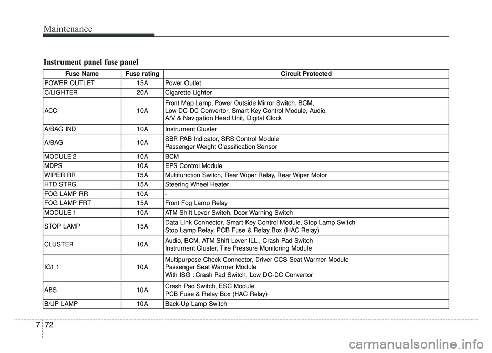
Instrument panel fuse panel
Fuse Name Fuse rating Circuit Protected
POWER OUTLET 15A Power Outlet
C/LIGHTER 20A Cigarette Lighter
ACC 10AFront Map Lamp, Power Outside Mirror Switch, BCM,
Low DC-DC Convertor, Smart Key Control Module, Audio,
A/V & Navigation Head Unit, Digital Clock
A/BAG IND 10A Instrument Cluster
A/BAG 10ASBR PAB Indicator, SRS Control Module
Passenger Weight Classification Sensor
MODULE 2 10A BCM
MDPS 10A EPS Control Module
WIPER RR 15A Multifunction Switch, Rear Wiper Relay, Rear Wiper Motor
HTD STRG 15A Steering Wheel Heater
FOG LAMP RR 10A -
FOG LAMP FRT 15A Front Fog Lamp Relay
MODULE 1 10A ATM Shift Lever Switch, Door Warning Switch
STOP LAMP 15AData Link Connector, Smart Key Control Module, Stop Lamp Switch
Stop Lamp Relay, PCB Fuse & Relay Box (HAC Relay)
CLUSTER 10AAudio, BCM, ATM Shift Lever ILL., Crash Pad Switch
Instrument Cluster, Tire Pressure Monitoring Module
IG1 1 10AMultipurpose Check Connector, Driver CCS Seat Warmer Module
Passenger Seat Warmer Module
With ISG : Crash Pad Switch, Low DC-DC Convertor
ABS 10ACrash Pad Switch, ESC Module
PCB Fuse & Relay Box (HAC Relay)
B/UP LAMP 10A Back-Up Lamp Switch
Page 423 of 477
773
Maintenance
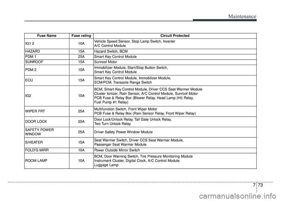
Fuse Name Fuse ratingCircuit Protected
IG1 2 10AVehicle Speed Sensor, Stop Lamp Switch, Inverter
A/C Control Module
HAZARD 15A Hazard Switch, BCM
PDM 1 25A Smart Key Control Module
SUNROOF 15A Sunroof Motor
PDM 2 10AImmobilizer Module, Start/Stop Button Switch,
Smart Key Control Module
ECU 15ASmart Key Control Module, Immobilizer Module,
ECM/PCM, Transaxle Range Switch
IG2 10ABCM, Smart Key Control Module, Driver CCS Seat Warmer Module
Cluster Ionizer, Rain Sensor, A/C Control Module, Sunroof Motor
PCB Fuse & Relay Box (Blower Relay, Head Lamp (HI) Relay,
Fuel Pump #1 Relay)
WIPER FRT 25AMultifunction Switch, Front Wiper Motor
PCB Fuse & Relay Box (Rain Sensor Relay, Front Wiper Relay)
DOOR LOCK 20ADoor Lock/Unlock Relay, Tail Gate Unlock Relay,
Two Turn Unlock Relay
SAFETY POWER
WINDOW 25A Driver Safety Power Window Module
S/HEATER 15ASeat Warmer Switch, Driver CCS Seat Warmer Module,
Passenger Seat Warmer Module
FOLD'G MIRR 10A Power Outside Mirror Switch
ROOM LAMP 10ABCM, Door Warning Switch, Tire Pressure Monitoring Module
Instrument Cluster, Digital Clock, A/C Control Module
Luggage Lamp
Page 426 of 477
Maintenance
76
7
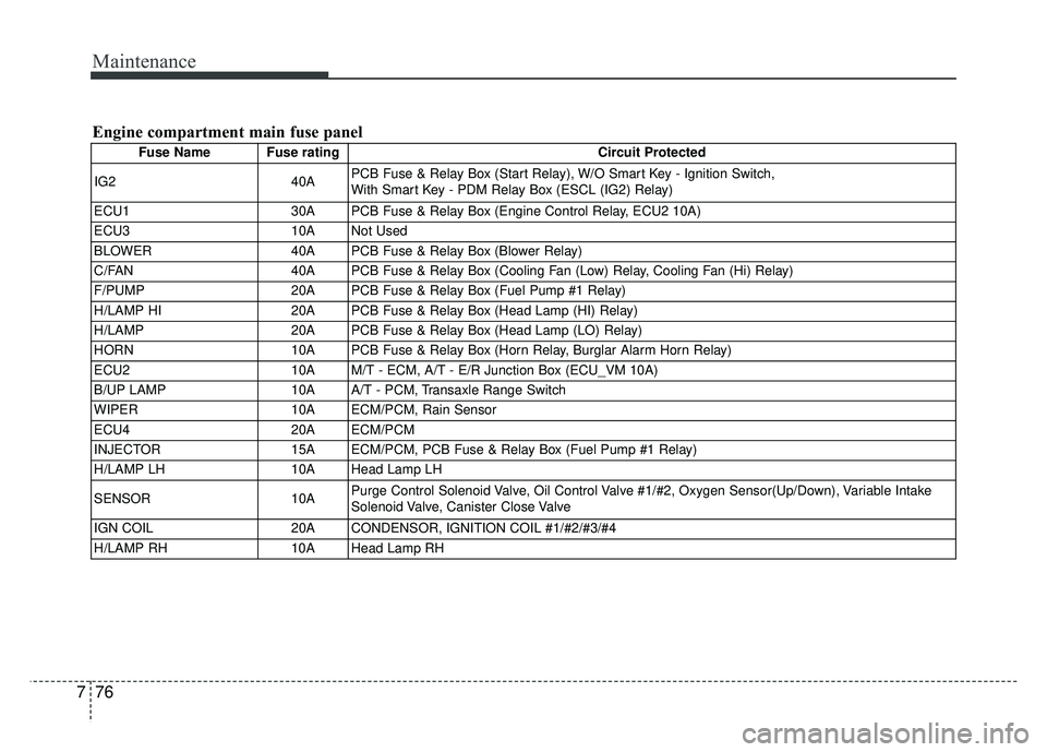
Engine compartment main fuse panel
Fuse Name Fuse rating Circuit Protected
IG2 40APCB Fuse & Relay Box (Start Relay), W/O Smart Key - Ignition Switch,
With Smart Key - PDM Relay Box (ESCL (IG2) Relay)
ECU1 30A PCB Fuse & Relay Box (Engine Control Relay, ECU2 10A)
ECU3 10A Not Used
BLOWER 40A PCB Fuse & Relay Box (Blower Relay)
C/FAN 40A PCB Fuse & Relay Box (Cooling Fan (Low) Relay, Cooling Fan (Hi) Relay)
F/PUMP 20A PCB Fuse & Relay Box (Fuel Pump #1 Relay)
H/LAMP HI 20A PCB Fuse & Relay Box (Head Lamp (HI) Relay)
H/LAMP 20A PCB Fuse & Relay Box (Head Lamp (LO) Relay)
HORN 10A PCB Fuse & Relay Box (Horn Relay, Burglar Alarm Horn Relay)
ECU2 10A M/T - ECM, A/T - E/R Junction Box (ECU_VM 10A)
B/UP LAMP 10A A/T - PCM, Transaxle Range Switch
WIPER 10A ECM/PCM, Rain Sensor
ECU4 20A ECM/PCM
INJECTOR 15A ECM/PCM, PCB Fuse & Relay Box (Fuel Pump #1 Relay)
H/LAMP LH 10A Head Lamp LH
SENSOR 10APurge Control Solenoid Valve, Oil Control Valve #1/#2, Oxygen Sensor(Up/Down), Variable Intake
Solenoid Valve, Canister Close Valve
IGN COIL 20A CONDENSOR, IGNITION COIL #1/#2/#3/#4
H/LAMP RH 10A Head Lamp RH