engine KIA Sorento 2007 1.G Manual Online
[x] Cancel search | Manufacturer: KIA, Model Year: 2007, Model line: Sorento, Model: KIA Sorento 2007 1.GPages: 325, PDF Size: 5.01 MB
Page 257 of 325
69
In case of an emergency
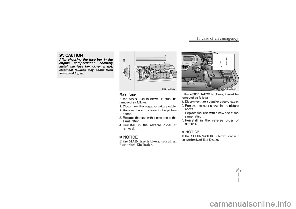
Main fuseIf the MAIN fuse is blown, it must be
removed as follows:
1. Disconnect the negative battery cable.
2. Remove the nuts shown in the pictureabove.
3. Replace the fuse with a new one of the same rating.
4. Reinstall in the reverse order of removal.✽ ✽NOTICEIf the MAIN fuse is blown, consult an
Authorized Kia Dealer.
If the ALTERNATOR is blown, it must be
removed as follows:
1. Disconnect the negative battery cable.
2. Remove the nuts shown in the picture
above.
3. Replace the fuse with a new one of the same rating.
4. Reinstall in the reverse order of removal.✽ ✽NOTICEIf the ALTERNATOR is blown, consult
an Authorized Kia Dealer.
E2BLA606A
CAUTION
After checking the fuse box in the
engine compartment, securelyinstall the fuse box cover. If not,electrical failures may occur from water leaking in.
OBL066001
Page 258 of 325
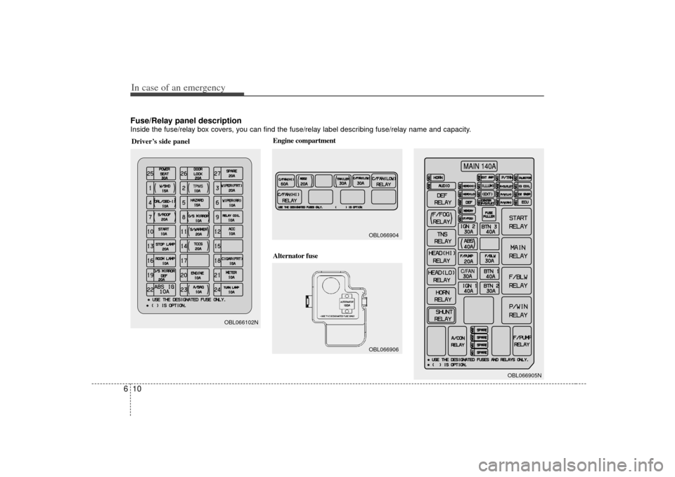
Fuse/Relay panel descriptionInside the fuse/relay box covers, you can find the fuse/relay label describing fuse/relay name and capacity.In case of an emergency10
6Driver’s side panel
TPMSTPMS
OBL066102N
MAIN 140AMAIN 140AC/FANC/FAN
OBL066905N
Engine compartment
Alternator fuse
OBL066904OBL066906
Page 259 of 325
611
In case of an emergency
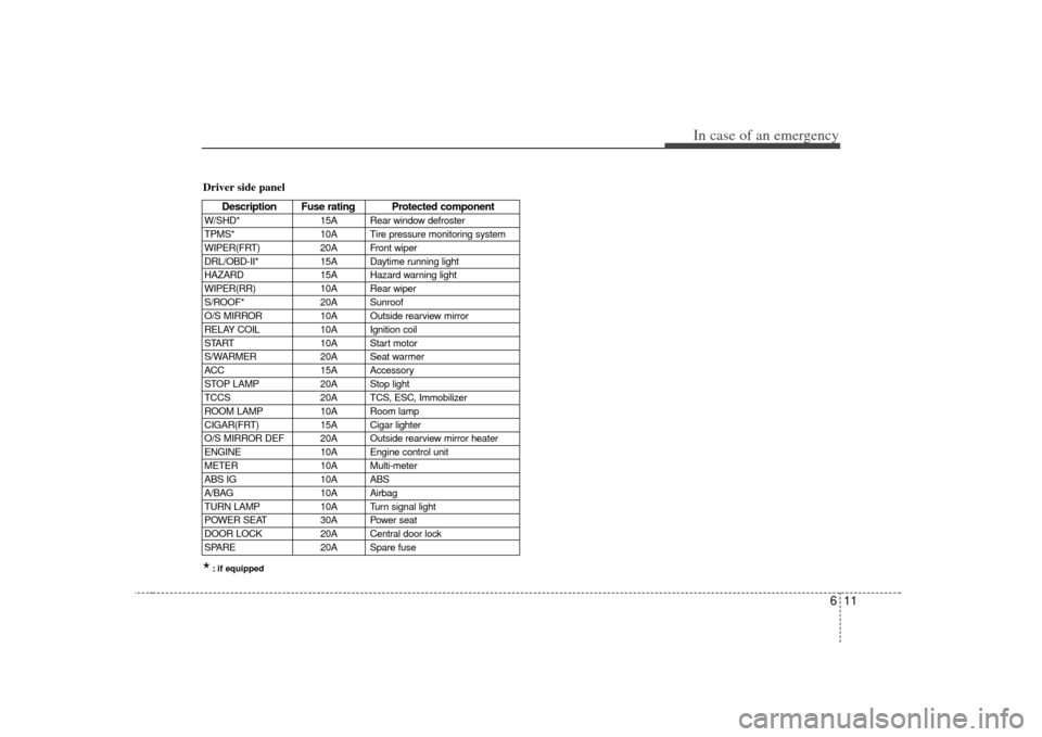
Driver side panel
Description Fuse rating Protected component
W/SHD*15A Rear window defroster
TPMS* 10A Tire pressure monitoring system
WIPER(FRT) 20A Front wiper
DRL/OBD-II* 15A Daytime running light
HAZARD 15A Hazard warning light
WIPER(RR) 10A Rear wiper
S/ROOF* 20A Sunroof
O/S MIRROR 10A Outside rearview mirror
RELAY COIL 10A Ignition coil
START 10A Start motor
S/WARMER 20A Seat warmer
ACC 15A Accessory
STOP LAMP 20A Stop light
TCCS 20A TCS, ESC, Immobilizer
ROOM LAMP 10A Room lamp
CIGAR(FRT) 15A Cigar lighter
O/S MIRROR DEF 20A Outside rearview mirror heater
ENGINE 10A Engine control unit
METER 10A Multi-meter
ABS IG 10A ABS
A/BAG 10A Airbag
TURN LAMP 10A Turn signal light
POWER SEAT 30A Power seat
DOOR LOCK 20A Central door lock
SPARE 20A Spare fuse*: if equipped
Page 260 of 325
In case of an emergency12
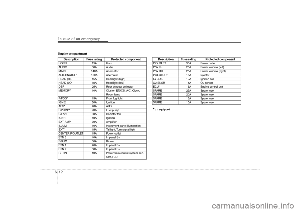
6Engine compartment
Description Fuse rating Protected component
HORN 15A Horn
AUDIO 30A Audio
MAIN 140A Alternator
ALTERNATOR* 150A Alternator
HEAD (HI) 15A Headlight (high)
HEAD (LO) 15A Headlight (low)
DEF 25A Rear window defroster
MEMORY 10A Cluster, ETACS, A/C, Clock,
Room lamp
F/FOG* 15A Front fog light
IGN 2 30A Ignition
ABS* 40A ABS
F/PUMP* 20A Fuel pump
C/FAN 30A Radiator fan
IGN 1 40A Ignition
EXT AMP 30A Amplifier
ILLUMI 10A Instrument panel illumination
EXT* 15A Taillight, Turn signal lightCENTER P/OUTLET
15A Power outlet
BTN 3 40A In panel B+
F/BLW 30A Blower
BTN 1 40A In panel B+
BTN 2 30A In panel B+
P/TRN 10A Power train control system sen- sors,TCU
*: if equippedDescription Fuse rating Protected component
P/OUTLET30A Power outlet
P/W LH 25A Power window (left)
P/W RH 25A Power window (right)
INJECTOR* 15A Injector
IG COIL 10A Ignition coil
O2 SNSR 15A O2 sensor
ECU* 15A Engine control unit
SPARE 25A Spare fuse
SPARE 20A Spare fuse
SPARE 15A Spare fuse
SPARE 10A Spare fuse
Page 261 of 325
613
In case of an emergency
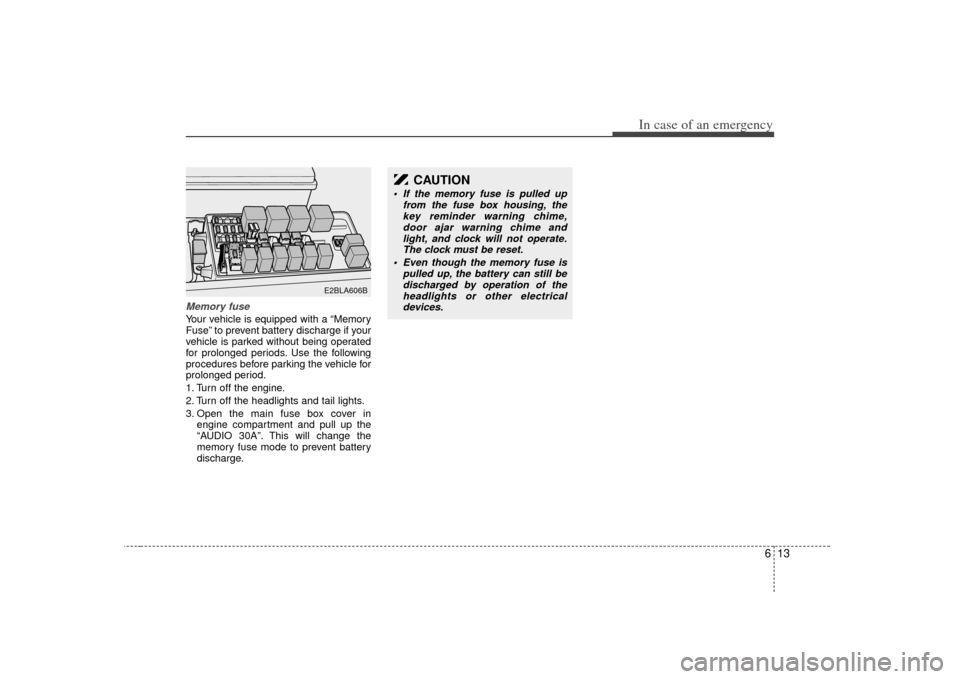
Memory fuseYour vehicle is equipped with a “Memory
Fuse” to prevent battery discharge if your
vehicle is parked without being operated
for prolonged periods. Use the following
procedures before parking the vehicle for
prolonged period.
1. Turn off the engine.
2. Turn off the headlights and tail lights.
3. Open the main fuse box cover inengine compartment and pull up the
“AUDIO 30A”. This will change the
memory fuse mode to prevent battery
discharge.
E2BLA606B
CAUTION
If the memory fuse is pulled up from the fuse box housing, thekey reminder warning chime,door ajar warning chime and light, and clock will not operate.The clock must be reset.
Even though the memory fuse is pulled up, the battery can still bedischarged by operation of theheadlights or other electricaldevices.
Page 265 of 325
617
In case of an emergency
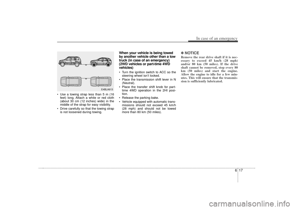
Use a towing strap less than 5 m (16feet) long. Attach a white or red cloth
(about 30 cm (12 inches) wide) in the
middle of the strap for easy visibility.
Drive carefully so that the towing strap is not loosened during towing.
When your vehicle is being towed
by another vehicle other than a tow
truck (in case of an emergency)
(2WD vehicles or part-time 4WD
vehicles) Turn the ignition switch to ACC so thesteering wheel isn’t locked.
Place the transmission shift lever in N (Neutral).
Place the transfer shift knob for part- time 4WD operation in the 2HI posi-
tion.
Release the parking bake.
Vehicle equipped with automatic trans- missions should not exceed 45 km/h
(28 mph) and should not be towed
more than 80 km (50 miles).
✽ ✽ NOTICERemove the rear drive shaft if it is nec-
essary to exceed 45 km/h (28 mph)
and/or 80 km (50 miles). If the drive
shaft cannot be removed, stop every 80
km (50 miles) and start the engine.
Allow the engine to idle for a few min-
utes. This will ensure that the transmis-
sion is sufficiently lubricated.
E4BLA613
Page 269 of 325
621
In case of an emergency
Changing tires Jacking instructions The jack is provided for emergency
tire changing only.
Follow jacking instructions to reduce
the possibility of personal injury.
WARNING
- Changingtires
Never attempt vehicle repairs in the traffic lanes of a public
road or highway.
Always move the vehicle com- pletely off the road and onto
the shoulder before trying to
change a tire. If you cannot
find a firm, level place off the
road, call a towing service
company for assistance.
Be sure to use the correct front and rear jacking posi-
tions on the vehicle; never use
the bumpers or any other part
of the vehicle for jack support.
The vehicle can easily roll off the jack causing serious
injury or death. Never allow
any portion of your body to
get beneath the vehicle while
using the jack.
(Continued)
(Continued)
Do not start or run the enginewhile the vehicle is on the
jack.
Do not allow anyone to remain in the vehicle while it is on the
jack.
Make sure any children pres- ent are in a secure place away
from the road and from the
vehicle to be raised with the
jack.
Page 274 of 325
7
Maintenance services / 7-2
Maintenance schedule / 7-3
Owner maintenance / 7-7
Engine compartment / 7-10
Engine oil / 7-11
Engine cooling system / 7-12
Brake fluid / 7-14
Power steering / 7-15
Automatic transmission / 7-16
Lubricants and fluids / 7-18
Air cleaner / 7-19
Climate control air filter / 7-20
Wiper blades / 7-20
Battery / 7-22
Tires and wheels / 7-25
Lubricant specifications / 7-37
Exterior care / 7-39
Interior care / 7-42
Maintenance
Page 276 of 325
73
Maintenance
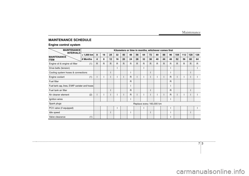
MAINTENANCE SCHEDULE Engine control system
MAINTENANCEINTERVALS
MAINTENANCE
ITEM
Replace every 160,000 km
Kilometers or time in months, whichever comes first
× 1,000 km 8 16 24 32 40 48 56 64 72 80 88 96 104 112 120 128
# Months 4 8 12 16 20 24 28 32 36 40 44 48 52 56 60 64
Engine oil & engine oil filter (1) R R R R R R RRRRRRR RRR
Drive belts (tension) I I I I
Cooling system hoses & connections I I I I I
Engine coolant (1) I I I I I R IIIIIRI III
Fuel filter R R
Fuel tank cap, lines, EVAP canister and hoses I I
Fuel tank air filter I R I R I
Air cleaner element (2) I I I I I R IIIIIRI III
Ignition wires I I
Spark plugs
PCV valve (if equipped) I I I I
Idle speed I I I I I
Valve clearance (1) I
Page 279 of 325
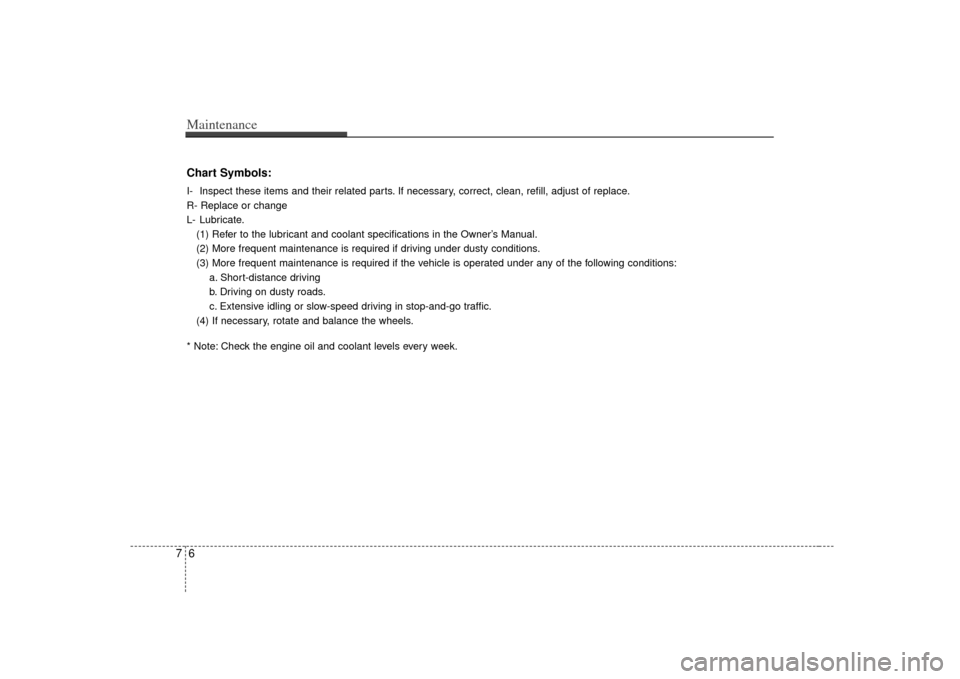
Maintenance67Chart Symbols:I- Inspect these items and their related parts. If necessary, correct, clean, refill, adjust of replace.
R- Replace or change
L- Lubricate.(1) Refer to the lubricant and coolant specifications in the Owner’s Manual.
(2) More frequent maintenance is required if driving under dusty conditions.
(3) More frequent maintenance is required if the vehicle is operated under any of the following conditions: a. Short-distance driving
b. Driving on dusty roads.
c. Extensive idling or slow-speed driving in stop-and-go traffic.
(4) If necessary, rotate and balance the wheels.
* Note: Check the engine oil and coolant levels every week.