check engine KIA SORENTO 2018 Repair Manual
[x] Cancel search | Manufacturer: KIA, Model Year: 2018, Model line: SORENTO, Model: KIA SORENTO 2018Pages: 536, PDF Size: 13.42 MB
Page 477 of 536
Maintenance
66
7
FUSES
A vehicle’s electrical system is pro-
tected from electrical overload dam-
age by fuses.
This vehicle has 2 (or 3) fuse panels,
one located in the driver’s side panel
bolster, the other in the engine com-
partment near the battery.
If any of your vehicle’s lights, acces-
sories, or controls do not work, check
the appropriate circuit fuse. If a fuse
has blown, the element inside the
fuse will melt.
If the electrical system does not
work, first check the driver’s side
fuse panel.
Always replace a blown fuse with
one of the same rating.
If the replacement fuse blows, this
indicates an electrical problem. Avoid
using the system involved and imme-
diately consult an authorized Kia
dealer.
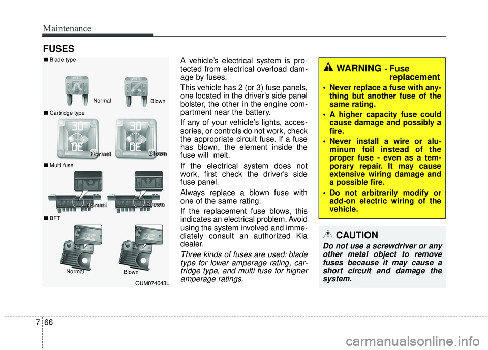
Three kinds of fuses are used: blade
type for lower amperage rating, car-tridge type, and multi fuse for higheramperage ratings.
WARNING - Fuse
replacement
Never replace a fuse with any- thing but another fuse of the
same rating.
A higher capacity fuse could cause damage and possibly a
fire.
Never install a wire or alu- minum foil instead of the
proper fuse - even as a tem-
porary repair. It may cause
extensive wiring damage and
a possible fire.
Do not arbitrarily modify or add-on electric wiring of the
vehicle.
CAUTION
Do not use a screwdriver or anyother metal object to removefuses because it may cause ashort circuit and damage thesystem.
OUM074043L
Normal
■
Blade type
■ Cartridge type
■ Multi fuse Blown
N N
N N
o o
o o
r r
r r
m m
m m
a a
a a
l l
l l B B
B B
l l
l l
o o
o o
w w
w w
n n
n n
Normal Blo
wn
■
BFT N N
N N
o o
o o
r r
r r
m m
m m
a a
a a
l l
l l B B
B B
l l
l l
o o
o o
w w
w w
n n
n n
Page 478 of 536
767
Maintenance
✽ ✽NOTICE
• When replacing fuse, turn the
ignition “OFF” and turn off
switches of all electrical devices
then remove battery (-) terminal.
• The actual fuse/relay panel label may differ from equipped items.
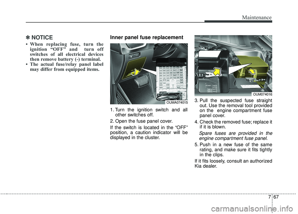
Inner panel fuse replacement
1. Turn the ignition switch and all
other switches off.
2. Open the fuse panel cover.
If the switch is located in the “OFF”
position, a caution indicator will be
displayed in the cluster. 3. Pull the suspected fuse straight
out. Use the removal tool provided
on the engine compartment fuse
panel cover.
4. Check the removed fuse; replace it if it is blown.
Spare fuses are provided in theengine compartment fuse panel.
5. Push in a new fuse of the same rating, and make sure it fits tightly
in the clips.
If it fits loosely, consult an authorized
Kia dealer.
OUMA074015
OUM074016
Page 479 of 536
Maintenance
68
7
If you do not have a spare, use a
fuse of the same rating from a circuityou may not need for operating thevehicle, such as the power outletfuse.
If the head lamp, turn signal lamp,
stop signal lamp, fog lamp, DRL, tail
lamp, HMSL do not work and the
fuses are OK, check the fuse panel
in the engine compartment. If a fuse
is blown, it must be replaced.
✽ ✽ NOTICE
If the headlamp, fog lamp, turn sig-
nal lamp, or tail lamp malfunction
even without any problem to the
lamps, have the vehicle checked by
an authorized Kia dealer for assis-
tance.
✽ ✽NOTICE - Fuse Panel Covers
• Put all switches in ON when driv-
ing.
• If the vehicle remains idle for over 1 month, put all switches in OFF
to prevent the batteries from being
discharged.
• Excluding long-term parking for over 1 month, the contact points of
switches may wear out upon
extensive use. Please refrain from
excessive use of switches.
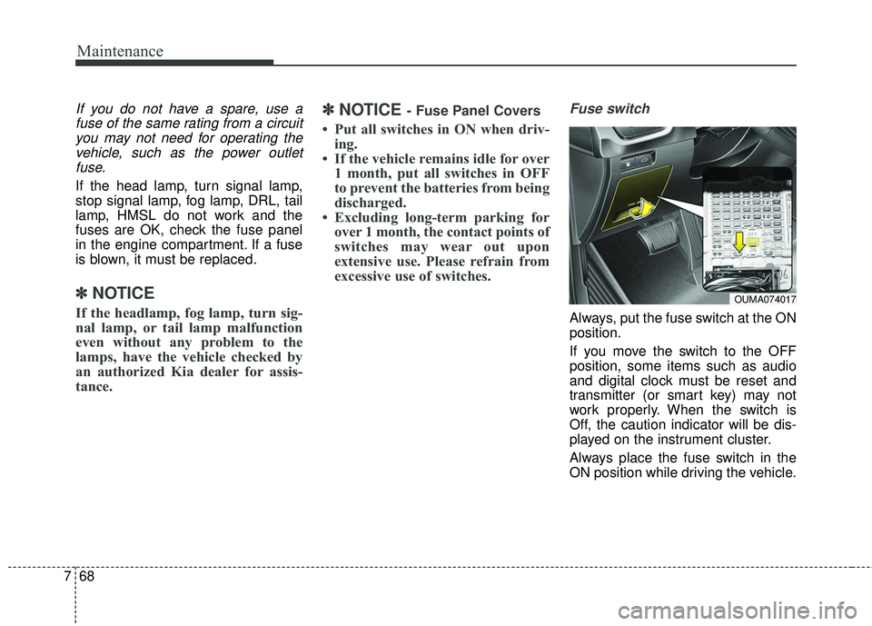
Fuse switch
Always, put the fuse switch at the ON
position.
If you move the switch to the OFF
position, some items such as audio
and digital clock must be reset and
transmitter (or smart key) may not
work properly. When the switch is
Off, the caution indicator will be dis-
played on the instrument cluster.
Always place the fuse switch in the
ON position while driving the vehicle.
OUMA074017
Page 480 of 536
769
Maintenance
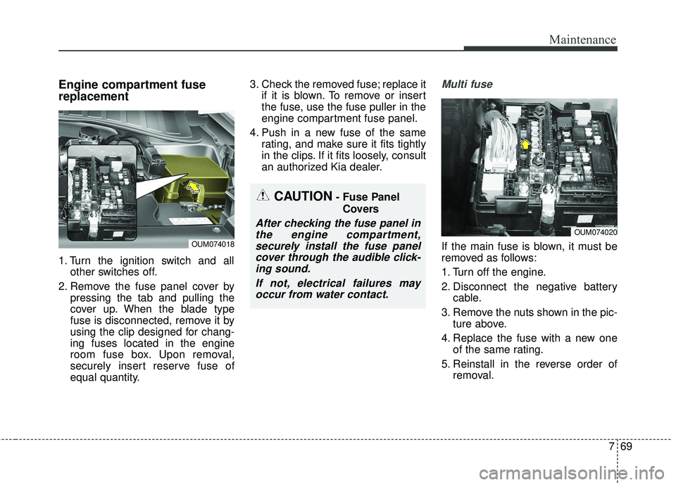
Engine compartment fuse
replacement
1. Turn the ignition switch and allother switches off.
2. Remove the fuse panel cover by pressing the tab and pulling the
cover up. When the blade type
fuse is disconnected, remove it by
using the clip designed for chang-
ing fuses located in the engine
room fuse box. Upon removal,
securely insert reserve fuse of
equal quantity. 3. Check the removed fuse; replace it
if it is blown. To remove or insert
the fuse, use the fuse puller in the
engine compartment fuse panel.
4. Push in a new fuse of the same rating, and make sure it fits tightly
in the clips. If it fits loosely, consult
an authorized Kia dealer.
Multi fuse
If the main fuse is blown, it must be
removed as follows:
1. Turn off the engine.
2. Disconnect the negative batterycable.
3. Remove the nuts shown in the pic- ture above.
4. Replace the fuse with a new one of the same rating.
5. Reinstall in the reverse order of removal.
OUM074020
CAUTION- Fuse Panel
Covers
After checking the fuse panel inthe engine compartment,securely install the fuse panelcover through the audible click-ing sound.
If not, electrical failures mayoccur from water contact.
OUM074018
Page 481 of 536
Maintenance
70
7
✽ ✽
NOTICE
Do not disassemble nor assemble the
multi fuse when it is secured with
nuts and bolts. Incorrect or partial
assembly torque may cause a fire.
Have the vehicle checked by an
authorized Kia dealer.
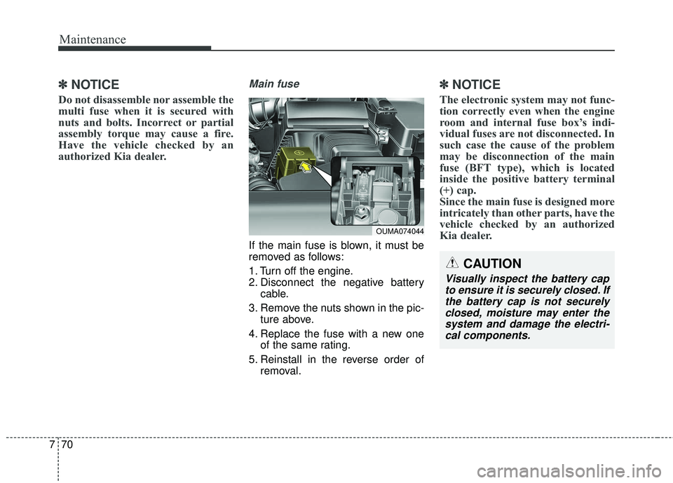
Main fuse
If the main fuse is blown, it must be
removed as follows:
1. Turn off the engine.
2. Disconnect the negative battery
cable.
3. Remove the nuts shown in the pic- ture above.
4. Replace the fuse with a new one of the same rating.
5. Reinstall in the reverse order of removal.
✽ ✽NOTICE
The electronic system may not func-
tion correctly even when the engine
room and internal fuse box’s indi-
vidual fuses are not disconnected. In
such case the cause of the problem
may be disconnection of the main
fuse (BFT type), which is located
inside the positive battery terminal
(+) cap.
Since the main fuse is designed more
intricately than other parts, have the
vehicle checked by an authorized
Kia dealer.
OUMA074044
CAUTION
Visually inspect the battery cap
to ensure it is securely closed. Ifthe battery cap is not securelyclosed, moisture may enter thesystem and damage the electri-cal components.
Page 493 of 536
Maintenance
82
7
LIGHT BULBS
Please prepare lamps with appropri-
ate standards in case of emergen-
cies. (Refer to chapter 8 for further
information)
When changing lamps and sorts,
first turn off the engine at a safe
place, firmly apply the side brake and
take out the battery’s negative (-) ter-
minal.Use only the bulbs of the specified
wattage.✽ ✽ NOTICE
• If the light bulb or lamp connector
is removed from an operating
lamp activated by electricity, the
fuse box’s electronic device may
scan it as a malfunction.
Therefore, a lamp malfunction
history may be recorded in
Diagnostic Trouble Code (DTC) in
the fuse box.
• It is normal for an operating lamp may blink temporarily. Since this
occurrence is due stabilization
function of the vehicle’s electronic
control device, if the lamp lights
up normally after temporary
blinking, there is no problem in
the vehicle.
However, if the lamp continues to
blink several times or turn off
completely, there may be an error
in the vehicle’s electronic control
device. So please have the vehicle
checked by an authorized Kia
dealer immediately.
WARNING - Working on
the lights
Prior to working on the light,
firmly apply the parking brake,
ensure that the ignition switch
is turned to the LOCK position
and turn off the lights to avoid
sudden movement of the vehi-
cle and burning your fingers or
receiving an electric shock.
CAUTION -Light replace-
ment
Be sure to replace the burned-
out bulb with one of the samewattage rating. Otherwise, itmay cause damage to the fuseor electric wiring system.
CAUTION -Headlamp
Lens
To prevent damage, do notclean headlamp lens with chem-ical solvents or strong deter-gents.
Page 513 of 536
Maintenance
102
7
Canister
Fuel vapors generated inside the fuel
tank are absorbed and stored in the
onboard canister. When the engine is
running, the fuel vapors absorbed in
the canister are drawn into the surge
tank through the purge control sole-
noid valve.
Purge Control Solenoid Valve
(PCSV)
The purge control solenoid valve is
controlled by the Engine Control
Module (ECM); when the engine
coolant temperature is low during
idling, the PCSV closes so that evap-
orated fuel is not taken into the
engine. After the engine warms up
during ordinary driving, the PCSV
opens to introduce evaporated fuel to
the engine.
3. Exhaust emission control system
The Exhaust Emission Control
System is a highly effective system
which controls exhaust emissions
while maintaining good vehicle per-
formance.
Vehicle modifications
This vehicle should not be modified.
Modification of your vehicle could
affect its performance, safety or
durability and may even violate gov-
ernmental safety and emissions reg-
ulations.
In addition, damage or performance
problems resulting from any modifi-
cation may not be covered under
warranty.
If you use unauthorized electronic
devices, it may cause the vehicle to
operate abnormally, wire damage,
battery discharge and fire. For your
safety, do not use unauthorized
electronic devices.
Engine exhaust gas precautions
(carbon monoxide)
Carbon monoxide can be present with other exhaust fumes.
Therefore, if you smell exhaust
fumes of any kind inside your vehi-
cle, have it inspected and repaired
immediately. If you ever suspect
exhaust fumes are coming into
your vehicle, drive it only with all
the windows fully open. Have your
vehicle checked and repaired
immediately.
WARNING - Exhaust
Engine exhaust gases contain
carbon monoxide (CO). Though
colorless and odorless, it is
dangerous and could be lethal if
inhaled. Follow the instructions
on this page to avoid CO poi-
soning.
Page 530 of 536
Index
4I
Defroster . . . . . . . . . . . . . . . . . . . . . . . . . . . . . . . . . . . 4-\
129Rear window defroster . . . . . . . . . . . . . . . . . . . . . . 4-129
Dimensions . . . . . . . . . . . . . . . . . . . . . . . . . . . . . . . . . . . 8-\
2
Door locks. . . . . . . . . . . . . . . . . . . . . . . . . . . . . . . . . . . 4-\
22 Child-protector rear door lock . . . . . . . . . . . . . . . . . 4-25
Impact sensing door unlock system . . . . . . . . . . . . . 4-25
Operating door locks from inside the vehicle . . . . . 4-23
Operating door locks from outside the vehicle . . . . 4-22
Drive mode integrated control system . . . . . . . . . . . . . 5-81 Drive mode . . . . . . . . . . . . . . . . . . . . . . . . . . . . . . . . 5-81
Economical operation . . . . . . . . . . . . . . . . . . . . . . . . . . 5-97
Emergency starting . . . . . . . . . . . . . . . . . . . . . . . . . . . . . 6-5 Jump starting . . . . . . . . . . . . . . . . . . . . . . . . . . . . . . . 6-5
Push-starting . . . . . . . . . . . . . . . . . . . . . . . . . . . . . . . . 6-6
Emission control system . . . . . . . . . . . . . . . . . . . . . . . 7-101 Crankcase emission control system . . . . . . . . . . . . 7-101
Evaporative emission control (including ORVR:Onboard refueling vapor recovery) system . . . . . 7-101
Exhaust emission control system . . . . . . . . . . . . . . 7-102
Engine . . . . . . . . . . . . . . . . . . . . . . . . . . . . . . . . . . . . \
. . . 8-2
Engine compartment . . . . . . . . . . . . . . . . . . . . . . . . . . . . 2-6
Engine compartment . . . . . . . . . . . . . . . . . . . . . . . . . . . . 7-3
Engine coolant . . . . . . . . . . . . . . . . . . . . . . . . . . . . . . . 7-36 Changing the coolant . . . . . . . . . . . . . . . . . . . . . . . . 7-38
Checking the coolant level . . . . . . . . . . . . . . . . . . . . 7-36
Engine number . . . . . . . . . . . . . . . . . . . . . . . . . . . . . . . 8-11
Engine oil . . . . . . . . . . . . . . . . . . . . . . . . . . . . . . . . . . . 7-\
34 Changing the engine oil and filter . . . . . . . . . . . . . . 7-35
Checking the engine oil level. . . . . . . . . . . . . . . . . . 7-34
Engine start/stop button . . . . . . . . . . . . . . . . . . . . . . . . . 5-9 Engine start/stop button position . . . . . . . . . . . . . . . . 5-9
Illuminated engine start/stop button. . . . . . . . . . . . . . 5-9
Starting the engine with a smart key . . . . . . . . . . . . 5-11
Explanation of scheduled maintenance items . . . . . . . 7-29
Exterior features . . . . . . . . . . . . . . . . . . . . . . . . . . . . . 4-173 Roof rack . . . . . . . . . . . . . . . . . . . . . . . . . . . . . . . . 4-173
Exterior overview . . . . . . . . . . . . . . . . . . . . . . . . . . . . . . 2-2
Folding key . . . . . . . . . . . . . . . . . . . . . . . . . . . . . . . . . . . 4-\
5 Battery replacement . . . . . . . . . . . . . . . . . . . . . . . . . . 4-8
Immobilizer system . . . . . . . . . . . . . . . . . . . . . . . . . . 4-9
Key operations . . . . . . . . . . . . . . . . . . . . . . . . . . . . . . 4-5
Record your key number . . . . . . . . . . . . . . . . . . . . . . 4-5
Transmitter precautions . . . . . . . . . . . . . . . . . . . . . . . 4-7
Fuel filler lid . . . . . . . . . . . . . . . . . . . . . . . . . . . . . . . . . 4-46 Closing the fuel filler lid . . . . . . . . . . . . . . . . . . . . . 4-46
Emergency fuel filler lid release . . . . . . . . . . . . . . . 4-48
Opening the fuel filler lid. . . . . . . . . . . . . . . . . . . . . 4-46
Fuel requirements . . . . . . . . . . . . . . . . . . . . . . . . . . . . . . 1-2
F
E
D
Page 532 of 536
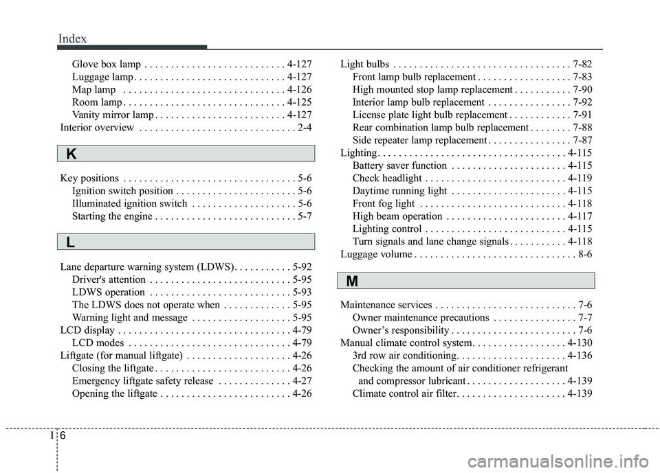
Index
6I
Glove box lamp . . . . . . . . . . . . . . . . . . . . . . . . . . . 4-127
Luggage lamp . . . . . . . . . . . . . . . . . . . . . . . . . . . . . 4-127
Map lamp . . . . . . . . . . . . . . . . . . . . . . . . . . . . . . . 4-126
Room lamp . . . . . . . . . . . . . . . . . . . . . . . . . . . . . . . 4-125
Vanity mirror lamp . . . . . . . . . . . . . . . . . . . . . . . . . 4-127
Interior overview . . . . . . . . . . . . . . . . . . . . . . . . . . . . . . 2-4
Key positions . . . . . . . . . . . . . . . . . . . . . . . . . . . . . . . . . 5-6 Ignition switch position . . . . . . . . . . . . . . . . . . . . . . . 5-6
Illuminated ignition switch . . . . . . . . . . . . . . . . . . . . 5-6
Starting the engine . . . . . . . . . . . . . . . . . . . . . . . . . . . 5-7
Lane departure warning system (LDWS) . . . . . . . . . . . 5-92 Driver's attention . . . . . . . . . . . . . . . . . . . . . . . . . . . 5-95
LDWS operation . . . . . . . . . . . . . . . . . . . . . . . . . . . 5-93
The LDWS does not operate when . . . . . . . . . . . . . 5-95
Warning light and message . . . . . . . . . . . . . . . . . . . 5-95
LCD display . . . . . . . . . . . . . . . . . . . . . . . . . . . . . . . . . 4-79 LCD modes . . . . . . . . . . . . . . . . . . . . . . . . . . . . . . . 4-79
Liftgate (for manual liftgate) . . . . . . . . . . . . . . . . . . . . 4-26 Closing the liftgate . . . . . . . . . . . . . . . . . . . . . . . . . . 4-26
Emergency liftgate safety release . . . . . . . . . . . . . . 4-27
Opening the liftgate . . . . . . . . . . . . . . . . . . . . . . . . . 4-26 Light bulbs . . . . . . . . . . . . . . . . . . . . . . . . . . . . . . . . . . 7-82\
Front lamp bulb replacement . . . . . . . . . . . . . . . . . . 7-83
High mounted stop lamp replacement . . . . . . . . . . . 7-90
Interior lamp bulb replacement . . . . . . . . . . . . . . . . 7-92
License plate light bulb replacement . . . . . . . . . . . . 7-91
Rear combination lamp bulb replacement . . . . . . . . 7-88
Side repeater lamp replacement . . . . . . . . . . . . . . . . 7-87
Lighting . . . . . . . . . . . . . . . . . . . . . . . . . . . . . . . . . . . . \
4-115 Battery saver function . . . . . . . . . . . . . . . . . . . . . . 4-115
Check headlight . . . . . . . . . . . . . . . . . . . . . . . . . . . 4-119
Daytime running light . . . . . . . . . . . . . . . . . . . . . . 4-115
Front fog light . . . . . . . . . . . . . . . . . . . . . . . . . . . . 4-118
High beam operation . . . . . . . . . . . . . . . . . . . . . . . 4-117
Lighting control . . . . . . . . . . . . . . . . . . . . . . . . . . . 4-115
Turn signals and lane change signals . . . . . . . . . . . 4-118
Luggage volume . . . . . . . . . . . . . . . . . . . . . . . . . . . . . . . 8-6
Maintenance services . . . . . . . . . . . . . . . . . . . . . . . . . . . 7-6 Owner maintenance precautions . . . . . . . . . . . . . . . . 7-7
Owner’s responsibility . . . . . . . . . . . . . . . . . . . . . . . . 7-6
Manual climate control system. . . . . . . . . . . . . . . . . . 4-130 3rd row air conditioning. . . . . . . . . . . . . . . . . . . . . 4-136
Checking the amount of air conditioner refrigerantand compressor lubricant . . . . . . . . . . . . . . . . . . . 4-139
Climate control air filter. . . . . . . . . . . . . . . . . . . . . 4-139
M
L
K