instrument cluster KIA Soul EV 2016 2.G User Guide
[x] Cancel search | Manufacturer: KIA, Model Year: 2016, Model line: Soul EV, Model: KIA Soul EV 2016 2.GPages: 524, PDF Size: 25.82 MB
Page 328 of 524
Driving your vehicle
28
5
✽ ✽
NOTICE
• When operating the vehicle on a
dynamometer, ensure that the
ESC is turned off (ESC OFF light
illuminated). If the ESC is left on,
it may prevent the vehicle speed
from increasing, and result in false
diagnosis.
• Turning the ESC off does not affect ABS or brake system opera-
tion.
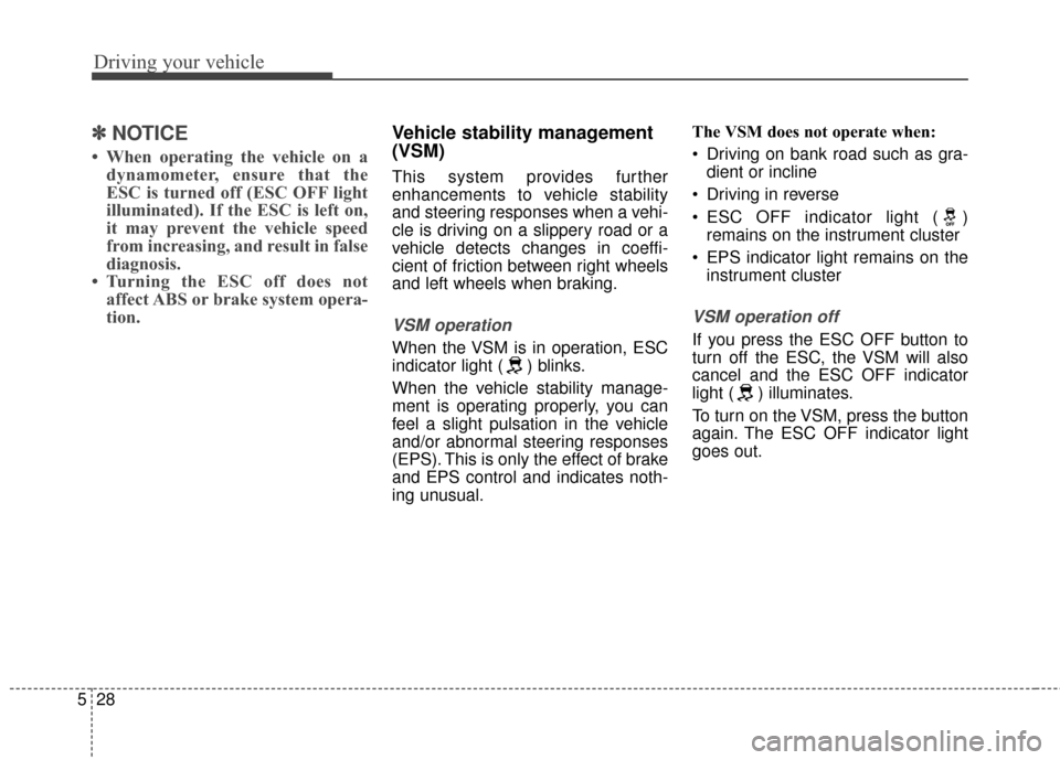
Vehicle stability management
(VSM)
This system provides further
enhancements to vehicle stability
and steering responses when a vehi-
cle is driving on a slippery road or a
vehicle detects changes in coeffi-
cient of friction between right wheels
and left wheels when braking.
VSM operation
When the VSM is in operation, ESC
indicator light ( ) blinks.
When the vehicle stability manage-
ment is operating properly, you can
feel a slight pulsation in the vehicle
and/or abnormal steering responses
(EPS). This is only the effect of brake
and EPS control and indicates noth-
ing unusual. The VSM does not operate when:
Driving on bank road such as gra-
dient or incline
Driving in reverse
ESC OFF indicator light ( ) remains on the instrument cluster
EPS indicator light remains on the instrument cluster
VSM operation off
If you press the ESC OFF button to
turn off the ESC, the VSM will also
cancel and the ESC OFF indicator
light ( ) illuminates.
To turn on the VSM, press the button
again. The ESC OFF indicator light
goes out.
Page 332 of 524
Driving your vehicle
32
5
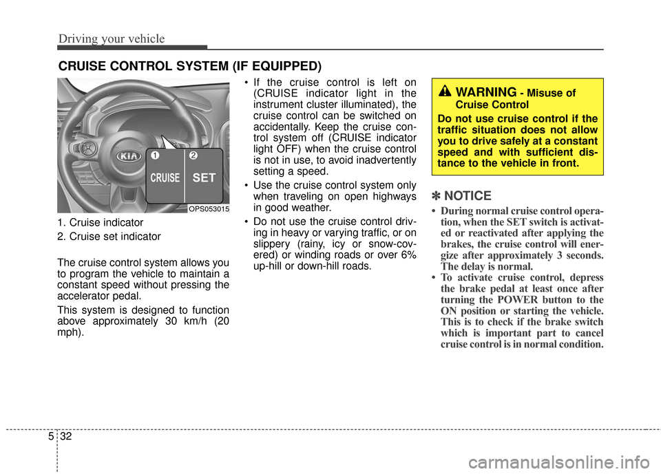
1. Cruise indicator
2. Cruise set indicator
The cruise control system allows you
to program the vehicle to maintain a
constant speed without pressing the
accelerator pedal.
This system is designed to function
above approximately 30 km/h (20
mph). If the cruise control is left on
(CRUISE indicator light in the
instrument cluster illuminated), the
cruise control can be switched on
accidentally. Keep the cruise con-
trol system off (CRUISE indicator
light OFF) when the cruise control
is not in use, to avoid inadvertently
setting a speed.
Use the cruise control system only when traveling on open highways
in good weather.
Do not use the cruise control driv- ing in heavy or varying traffic, or on
slippery (rainy, icy or snow-cov-
ered) or winding roads or over 6%
up-hill or down-hill roads.
✽ ✽ NOTICE
• During normal cruise control opera-
tion, when the SET switch is activat-
ed or reactivated after applying the
brakes, the cruise control will ener-
gize after approximately 3 seconds.
The delay is normal.
• To activate cruise control, depress the brake pedal at least once after
turning the POWER button to the
ON position or starting the vehicle.
This is to check if the brake switch
which is important part to cancel
cruise control is in normal condition.
CRUISE CONTROL SYSTEM (IF EQUIPPED)
OPS053015
WARNING- Misuse of
Cruise Control
Do not use cruise control if the
traffic situation does not allow
you to drive safely at a constant
speed and with sufficient dis-
tance to the vehicle in front.
Page 333 of 524
533
Driving your vehicle
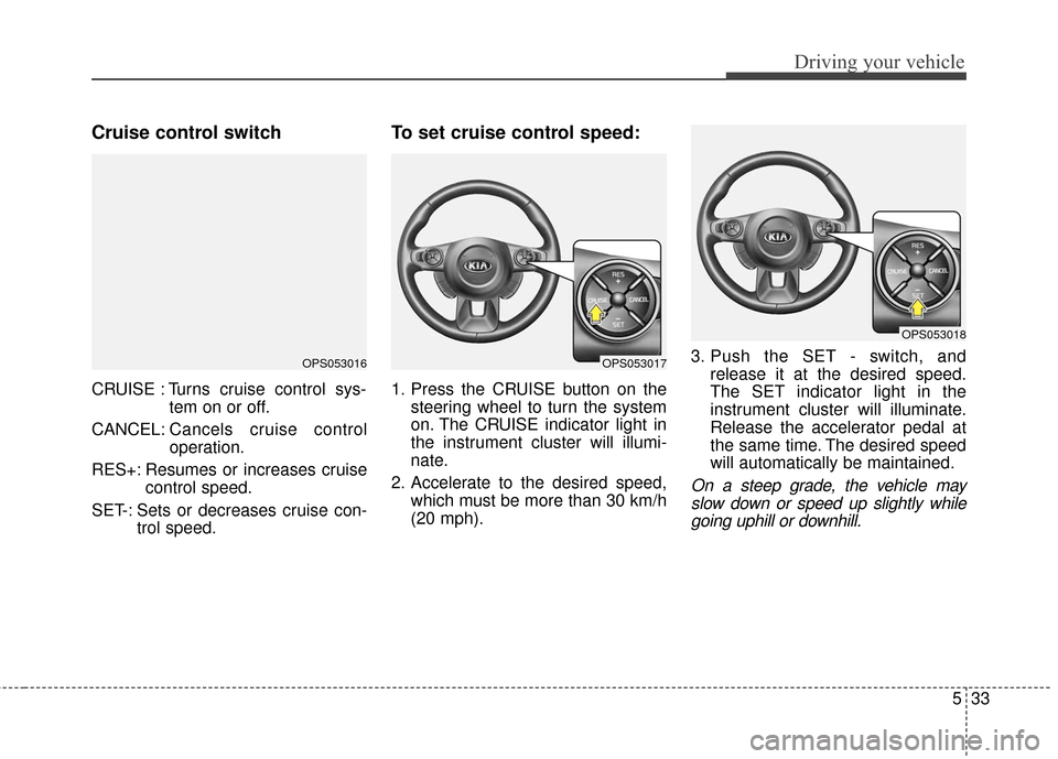
Cruise control switch
CRUISE : Turns cruise control sys-tem on or off.
CANCEL: Cancels cruise control
operation.
RES+: Resumes or increases cruise control speed.
SET-: Sets or decreases cruise con- trol speed.
To set cruise control speed:
1. Press the CRUISE button on thesteering wheel to turn the system
on. The CRUISE indicator light in
the instrument cluster will illumi-
nate.
2. Accelerate to the desired speed, which must be more than 30 km/h
(20 mph). 3. Push the SET - switch, and
release it at the desired speed.
The SET indicator light in the
instrument cluster will illuminate.
Release the accelerator pedal at
the same time. The desired speed
will automatically be maintained.
On a steep grade, the vehicle mayslow down or speed up slightly whilegoing uphill or downhill.
OPS053016OPS053017
OPS053018
Page 336 of 524
Driving your vehicle
36
5
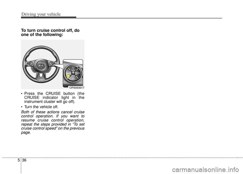
To turn cruise control off, do
one of the following:
Press the CRUISE button (the
CRUISE indicator light in the
instrument cluster will go off).
Turn the vehicle off.
Both of these actions cancel cruise control operation. If you want toresume cruise control operation,repeat the steps provided in “To setcruise control speed” on the previouspage.
OPS053017
Page 427 of 524
753
Maintenance
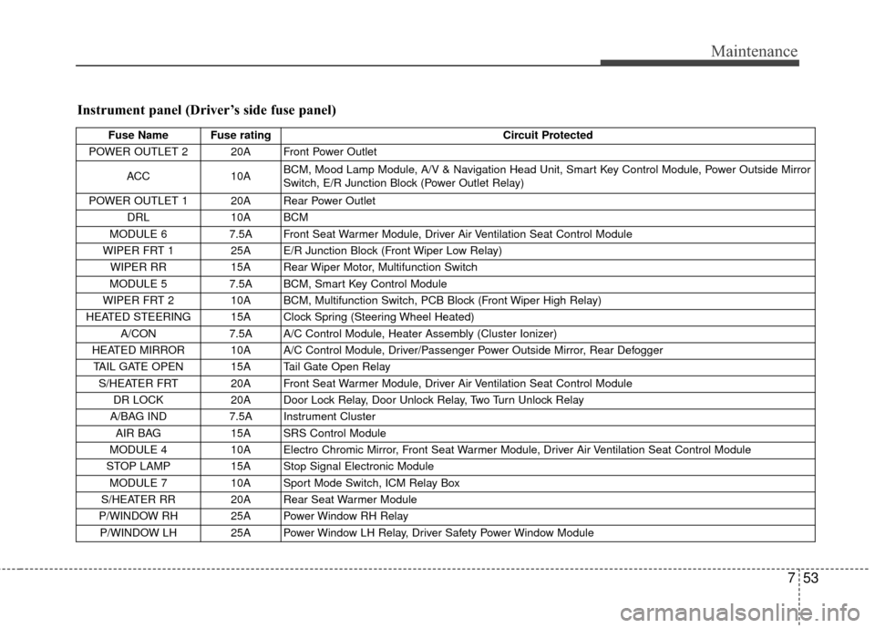
Instrument panel (Driver’s side fuse panel)
Fuse Name Fuse ratingCircuit Protected
POWER OUTLET 2 20A Front Power Outlet
ACC 10A BCM, Mood Lamp Module, A/V & Navigation Head Unit, Smart Key Control Module, Power Outside Mirror
Switch, E/R Junction Block (Power Outlet Relay)
POWER OUTLET 1 20A Rear Power Outlet DRL 10A BCM
MODULE 6 7.5A Front Seat Warmer Module, Driver Air Ventilation Seat Control Module
WIPER FRT 1 25A E/R Junction Block (Front Wiper Low Relay) WIPER RR 15A Rear Wiper Motor, Multifunction Switch
MODULE 5 7.5A BCM, Smart Key Control Module
WIPER FRT 2 10A BCM, Multifunction Switch, PCB Block (Front Wiper High Relay)
HEATED STEERING 15A Clock Spring (Steering Wheel Heated) A/CON 7.5A A/C Control Module, Heater Assembly (Cluster Ionizer)
HEATED MIRROR 10A A/C Control Module, Driver/Passenger Power Outside Mirror, Rear Defogger TAIL GATE OPEN 15A Tail Gate Open Relay S/HEATER FRT 20A Front Seat Warmer Module, Driver Air Ventilation Seat Control Module DR LOCK 20A Door Lock Relay, Door Unlock Relay, Two Turn Unlock Relay
A/BAG IND 7.5A Instrument Cluster
AIR BAG 15A SRS Control Module
MODULE 4 10A Electro Chromic Mirror, Front Seat Warmer Module, Driver Air Ventilation Seat Control Module
STOP LAMP 15A Stop Signal Electronic Module
MODULE 7 10A Sport Mode Switch, ICM Relay Box
S/HEATER RR 20A Rear Seat Warmer Module
P/WINDOW RH 25A Power Window RH Relay P/WINDOW LH 25A Power Window LH Relay, Driver Safety Power Window Module
Page 428 of 524
Maintenance
54
7
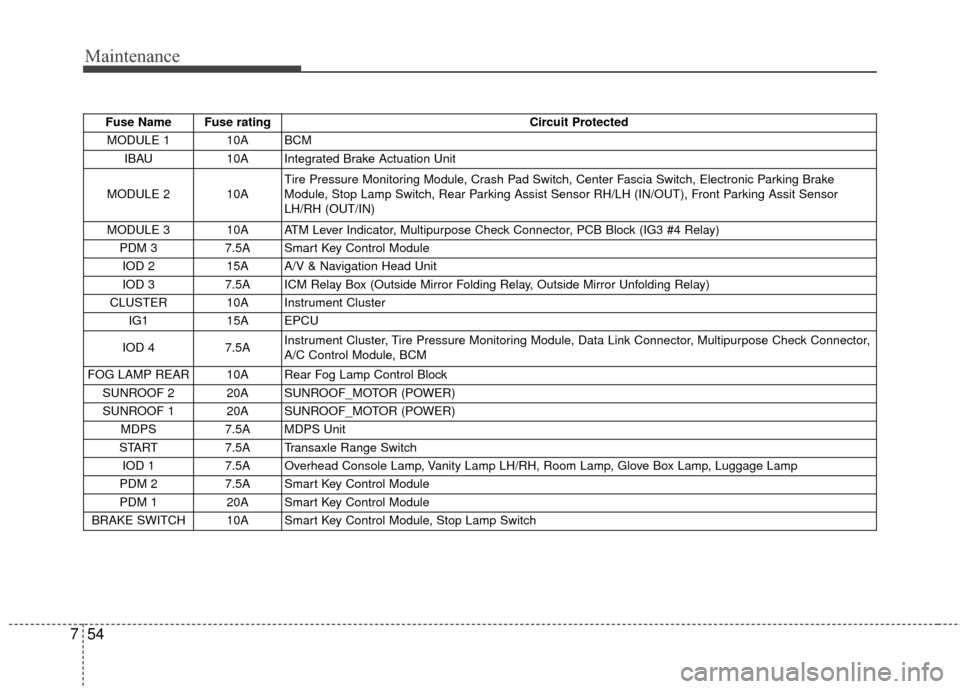
Fuse Name Fuse rating Circuit Protected
MODULE 1 10A BCM IBAU 10A Integrated Brake Actuation Unit
MODULE 2 10A Tire Pressure Monitoring Module, Crash Pad Switch, Center Fascia Switch, Electronic Parking Brake
Module, Stop Lamp Switch, Rear Parking Assist Sensor RH/LH (IN/OUT), Front Parking Assit Sensor
LH/RH (OUT/IN)
MODULE 3 10A ATM Lever Indicator, Multipurpose Check Connector, PCB Block (IG3 #4 Relay) PDM 3 7.5A Smart Key Control Module
IOD 2 15A A/V & Navigation Head Unit
IOD 3 7.5A ICM Relay Box (Outside Mirror Folding Relay, Outside Mirror Unfolding Relay)
CLUSTER 10A Instrument Cluster IG1 15A EPCU
IOD 4 7.5A Instrument Cluster, Tire Pressure Monitoring Module, Data Link Connector, Multipurpose Check Connector,
A/C Control Module, BCM
FOG LAMP REAR 10A Rear Fog Lamp Control Block SUNROOF 2 20A SUNROOF_MOTOR (POWER)
SUNROOF 1 20A SUNROOF_MOTOR (POWER) MDPS 7.5A MDPS Unit
START 7.5A Transaxle Range Switch
IOD 1 7.5A Overhead Console Lamp, Vanity Lamp LH/RH, Room Lamp, Glove Box Lamp, Luggage Lamp
PDM 2 7.5A Smart Key Control Module
PDM 1 20A Smart Key Control Module
BRAKE SWITCH 10A Smart Key Control Module, Stop Lamp Switch
Page 431 of 524
757
Maintenance
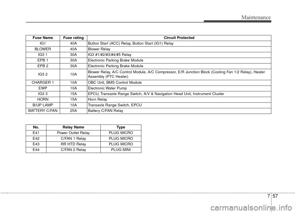
Fuse Name Fuse ratingCircuit Protected
IG1 40A Button Start (ACC) Relay, Button Start (IG1) Relay
BLOWER 40A Blower Relay IG3 1 30A IG3 #1/#2/#3/#4/#5 Relay
EPB 1 30A Electronic Parking Brake Module
EPB 2 30A Electronic Parking Brake Module
IG3 2 10A Blower Relay, A/C Control Module, A/C Compressor, E/R Junction Block (Cooling Fan 1/2 Relay), Heater
Assembly (PTC Heater)
CHARGER 1 10A OBC Unit, BMS Control Module EWP 10A Electronic Water Pump
IG3 3 15A EPCU, Transaxle Range Switch, A/V & Navigation Head Unit, Instrument Cluster
HORN 15A Horn Relay
B/UP LAMP 10A Transaxle Range Switch, EPCU
BATTERY C/FAN 25A Battery C/FAN Relay
No. Relay Name Type
E41 Power Outlet Relay PLUG MICRO
E42 C/FAN 1 Relay PLUG MICRO
E43 RR HTD Relay PLUG MICRO
E44 C/FAN 2 Relay PLUG MINI
Page 461 of 524
Index
4I
Fuses . . . . . . . . . . . . . . . . . . . . . . . . . . . . . . . . . . . . \
. . . 7-47Fuse/relay panel description. . . . . . . . . . . . . . . . . . . 7-52
Gross vehicle weight . . . . . . . . . . . . . . . . . . . . . . . . . . . 8-3
Hood . . . . . . . . . . . . . . . . . . . . . . . . . . . . . . . . . . . . \
. . . 4-22 Closing the hood . . . . . . . . . . . . . . . . . . . . . . . . . . . 4-22
Opening the hood . . . . . . . . . . . . . . . . . . . . . . . . . . 4-22
If the vehicle overheats . . . . . . . . . . . . . . . . . . . . . . . . . . 6-8
If the vehicle will not start . . . . . . . . . . . . . . . . . . . . . . . 6-4 If vehicle doesn’t turn over or turns over slowly . . . . 6-4
If you have a flat tire (with Tire Mobility Kit). . . . . . . 6-14 Components of the Tire Mobility Kit . . . . . . . . . . . 6-16
Distributing the sealant . . . . . . . . . . . . . . . . . . . . . . 6-18
Introduction . . . . . . . . . . . . . . . . . . . . . . . . . . . . . . . 6-14
Technical Data . . . . . . . . . . . . . . . . . . . . . . . . . . . . . 6-19
Using the Tire Mobility Kit . . . . . . . . . . . . . . . . . . . 6-17
In case of an emergency while driving . . . . . . . . . . . . . . 6-3 If the vehicle stalls at a crossroad or crossing . . . . . . 6-3 If vehicle stalls while driving . . . . . . . . . . . . . . . . . . . 6-3
If you have a flat tire while driving . . . . . . . . . . . . . . 6-3
Instrument cluster . . . . . . . . . . . . . . . . . . . . . . . . . . . . . 4-40 Gauges . . . . . . . . . . . . . . . . . . . . . . . . . . . . . . . . . . . 4-\
42
Instrument Cluster Control. . . . . . . . . . . . . . . . . . . . 4-41
LCD Display Control . . . . . . . . . . . . . . . . . . . . . . . . 4-41
Reduction gear shift indicator . . . . . . . . . . . . . . . . . 4-42
Instrument panel overview . . . . . . . . . . . . . . . . . . . . . . . 2-5
Interior features. . . . . . . . . . . . . . . . . . . . . . . . . . . . . . 4-117 Cargo area cover . . . . . . . . . . . . . . . . . . . . . . . . . . 4-124
Clothes hanger . . . . . . . . . . . . . . . . . . . . . . . . . . . . 4-122
Cup holder . . . . . . . . . . . . . . . . . . . . . . . . . . . . . . . 4-117
Floor mat anchor(s) . . . . . . . . . . . . . . . . . . . . . . . . 4-122
Luggage net holder. . . . . . . . . . . . . . . . . . . . . . . . . 4-123
Power outlet . . . . . . . . . . . . . . . . . . . . . . . . . . . . . . 4-121
Rear seat warmer . . . . . . . . . . . . . . . . . . . . . . . . . . 4-120
Seat air ventilation . . . . . . . . . . . . . . . . . . . . . . . . . 4-120
Seat warmer . . . . . . . . . . . . . . . . . . . . . . . . . . . . . . 4-118
Sunvisor . . . . . . . . . . . . . . . . . . . . . . . . . . . . . . . . . 4-117
Interior light . . . . . . . . . . . . . . . . . . . . . . . . . . . . . . . . . 4-90 Glove box lamp . . . . . . . . . . . . . . . . . . . . . . . . . . . . 4-92
Interior lamp AUTO cut . . . . . . . . . . . . . . . . . . . . . . 4-90
Luggage room lamp . . . . . . . . . . . . . . . . . . . . . . . . . 4-92
Map lamp . . . . . . . . . . . . . . . . . . . . . . . . . . . . . . . . 4-90
Room lamp . . . . . . . . . . . . . . . . . . . . . . . . . . . . . . . . 4-91
Vanity mirror lamp . . . . . . . . . . . . . . . . . . . . . . . . . . 4-92
Interior overview. . . . . . . . . . . . . . . . . . . . . . . . . . . . . . . 2-4
G
H
I
F
Page 488 of 524
23
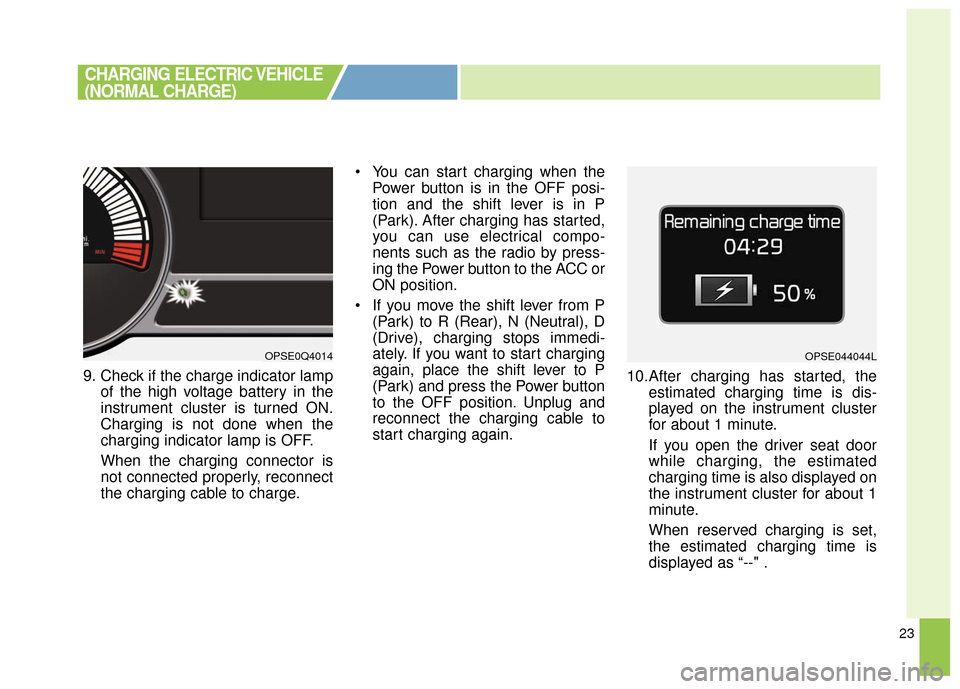
9. Check if the charge indicator lampof the high voltage battery in the
instrument cluster is turned ON.
Charging is not done when the
charging indicator lamp is OFF.
When the charging connector is
not connected properly, reconnect
the charging cable to charge. You can start charging when the
Power button is in the OFF posi-
tion and the shift lever is in P
(Park). After charging has started,
you can use electrical compo-
nents such as the radio by press-
ing the Power button to the ACC or
ON position.
If you move the shift lever from P (Park) to R (Rear), N (Neutral), D
(Drive), charging stops immedi-
ately. If you want to start charging
again, place the shift lever to P
(Park) and press the Power button
to the OFF position. Unplug and
reconnect the charging cable to
start charging again. 10.After charging has started, the
estimated charging time is dis-
played on the instrument cluster
for about 1 minute.
If you open the driver seat door
while charging, the estimated
charging time is also displayed on
the instrument cluster for about 1
minute.
When reserved charging is set,
the estimated charging time is
displayed as “--" .
OPSE0Q4014OPSE044044L
CHARGING ELECTRIC VEHICLE
(NORMAL CHARGE)
Page 494 of 524
29
❈Refer to the manual for each type
of quick charger for how to charge
and remove the charger.
❈ The shape of the charging con-
nector may vary depending on the
manufacturer.
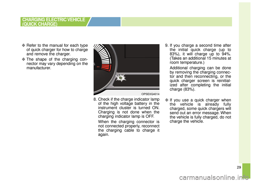
8. Check if the charge indicator lampof the high voltage battery in the
instrument cluster is turned ON.
Charging is not done when the
charging indicator lamp is OFF.
When the charging connector is
not connected properly, reconnect
the charging cable to charge it
again. 9. If you charge a second time after
the initial quick charge (up to
83%), it will charge up to 94%.
(Takes an additional 15 minutes at
room temperature.)
Additional charging can be done
by removing the charging connec-
tor and then reconnecting, or the
quick charger screen is reinitial-
ized after completing the initial
charge (83%).
❈ If you use a quick charger when
the vehicle is already fully
charged, some quick chargers will
send out an error message. When
the vehicle is fully charged, do not
charge the vehicle.
CHARGING ELECTRIC VEHICLE
(QUICK CHARGE)
OPSE0Q4014