turn signal KIA SOUL EV 2019 Owners Manual
[x] Cancel search | Manufacturer: KIA, Model Year: 2019, Model line: SOUL EV, Model: KIA SOUL EV 2019Pages: 455, PDF Size: 15.52 MB
Page 114 of 455
335
Safety features of your vehicle
How does the air bag system
operate
Air bags are activated (able toinflate if necessary) only when the
POWER button is turned to the ON
or the vehicle is in the ready ( )
mode.
The appropriate air bags inflate instantly in the event of a serious
frontal collision or side collision in
order to help protect the occupants
from serious physical injury.
There is no single speed at which the air bags will inflate.
Generally, air bags are designed to
inflate based upon the severity of a
collision and its direction. These
two factors determine whether the
sensors produce an electronic
deployment/ inflation signal.
Air bag deployment depends on a number of factors including vehicle
speed, angles of impact and the
density and stiffness of the vehi-
cles or objects which your vehicle
hits in the collision. The determin-
ing factors are not limited to those
mentioned above. The front air bags will completely
inflate and deflate in an instant.
It is virtually impossible for you to
see the air bags inflate during an
accident.
It is much more likely that you will
simply see the deflated air bags
hanging out of their storage com-
partments after the collision.
In addition to inflating in serious side collisions, side and/or curtain
air bags will inflate if the sensing
system detects a rollover.
When a rollover is detected, cur- tain air bags will remain inflated
longer to help provide protection
from ejection, especially when
used in conjunction with the seat
belts. In order to help provide protection,
the air bags must inflate rapidly.
The speed of the air bag inflation is
a consequence of extremely short
time in which to inflate the air bag
between the occupant and the
vehicle structures before the occu-
pant impacts those structures. This
speed of inflation reduces the risk
of serious or life-threatening
injuries and is thus a necessary
part of the air bag design.
However, air bag inflation can also
cause injuries which can include
facial abrasions, bruises and bro-
ken bones because the inflation
speed also causes the air bags to
expand with a great deal of force.
There are even circumstances under which contact with the
steering wheel or passenger air
bag can cause fatal injuries,
especially if the occupant is
positioned excessively close to
the steering wheel or passenger
air bag.
Page 145 of 455
Features of your vehicle
84
Smart key immobilizer system
Your vehicle is equipped with an elec-
tronic immobilizer system to reduce
the risk of unauthorized vehicle use.
Your immobilizer system is com-
prised of a small transponder in the
smart key and electronic devices
inside the vehicle.
With the immobilizer system, when-
ever you turn the POWER button to
the ON position by pressing the but-
ton while carrying the smart key, it
checks and determines and verifies if
the smart key is valid or not.
If the key is determined to be valid,
the vehicle will start.
If the key is determined to be invalid,
the vehicle will not start.
To deactivate the immobilizersystem:
Turn the POWER button to the ON
position by pressing the button while
carrying the smart key.
To activate the immobilizer system:
Turn the POWER button to the OFF
position. The immobilizer system
activates automatically. Without a
valid smart key for your vehicle, the
vehicle will not start.
In order to prevent theft of your vehi-
cle, do not leave spare keys anywhere
in your vehicle. Your Immobilizer pass-
word is a customer unique password
and should be kept confidential. Do
not leave this number anywhere in
your vehicle.
✽ ✽ NOTICE
When starting the vehicle, do not use
the key with other immobilizer keys
around. Otherwise the vehicle may
not start or may stop soon after it
starts. Keep each key separate in
order to avoid a starting malfunction.
Do not put metal accessories near
the smart key.
The vehicle may not start because
the metal accessories may interrupt
the transponder signal from transmit-
ting normally.
✽ ✽NOTICE
If you need additional keys or lose
your keys, contact an authorized
Kia dealer.
CAUTION- Immobilizer
damage
Do not expose your immobilizersystem to moisture, static elec-tricity and rough handling. Thismay damage your immobilizer.
CAUTION- Immobilizer
alterations
Do not change, alter or adjustthe immobilizer system becauseit could cause the immobilizersystem to malfunction.
Page 188 of 455
451
Features of your vehicle
Lamp
One Touch Turn Lamp (if equipped)
If this item is checked, the lane
change signals will blink 3, 5 or 7
times when the turn signal lever is
moved slightly.
Head Lamp Delay (if equipped)
If this item is checked, the headlamp
delay function will be activated.
Settings
Language
Choose the language you prefer
within the LCD.
Temperature Unit
Convert the temperature unit from °C
to °F or from °F to °C.
Welcome Sound (if equipped)
If this item is checked, the welcome
sound function will be activated.Energy Consumption Auto Reset
The average energy consumption will
reset automatically when charge the
high voltage battery more than 10%
The average energy consumption
will not reset automatically when
charge the high voltage battery more
than 10%
Page 211 of 455
Features of your vehicle
74
4
This indicator light illuminates for 2
seconds and goes off:
When the vehicle can not detect
the smart key which is in the vehi-
cle while the POWER button is ON.
In this case, have your vehicle
inspected by an authorized Kia
dealer.
This indicator light blinks:
When the battery of the smart key is weak.
- At this time, you can not start thevehicle. However, you can start the
vehicle if you press the POWER
button with the smart key. (For
more details, refer to “Starting the
vehicle” in chapter 5).
When there is a malfunction with the immobilizer system.
In this case, have your vehicle
inspected by an authorized Kia
dealer.Turn Signal Indicator
Light
This indicator light blinks:
When you turn the turn signal light on.
If any of the following occurs, there
may be a malfunction with the turn
signal system. In this case, have your
vehicle inspected by an authorized
Kia dealer. - The indicator light does not blinkbut illuminates.
- The indicator light blinks more rapidly.
- The indicator light does not illumi- nate at all.
High Beam Indicator
Light
This indicator light illuminates:
When the headlights are on and in the high beam position
When the turn signal lever is pulled into the Flash-to-Pass position.
Light ON Indicator Light
This indicator light illuminates:
When the tail lights or headlightsare on.
Page 222 of 455
485
Features of your vehicle
Turn signals and lane change
signals
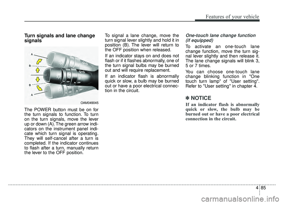
The POWER button must be on for
the turn signals to function. To turn
on the turn signals, move the lever
up or down (A). The green arrow indi-
cators on the instrument panel indi-
cate which turn signal is operating.
They will self-cancel after a turn is
completed. If the indicator continues
to flash after a turn, manually return
the lever to the OFF position.To signal a lane change, move the
turn signal lever slightly and hold it in
position (B). The lever will return to
the OFF position when released.
If an indicator stays on and does not
flash or if it flashes abnormally, one of
the turn signal bulbs may be burned
out and will require replacement.
If an indicator flash is abnormally
quick or slow, a bulb may be burned
out or have a poor electrical connec-
tion in the circuit.
One-touch lane change function
(if equipped)
To activate an one-touch lane
change function, move the turn sig-
nal lever slightly and then release it.
The lane change signals will blink 3,
5 or 7 times.
You can choose one-touch lane
change blinking function in "One
touch turn lamp" of "User setting".
Refer to "User setting" in chapter 4.
✽ ✽ NOTICE
If an indicator flash is abnormally
quick or slow, the bulb may be
burned out or have a poor electrical
connection in the circuit.OAM049045
Page 335 of 455
What to do in an emergency
26
ROAD WARNING
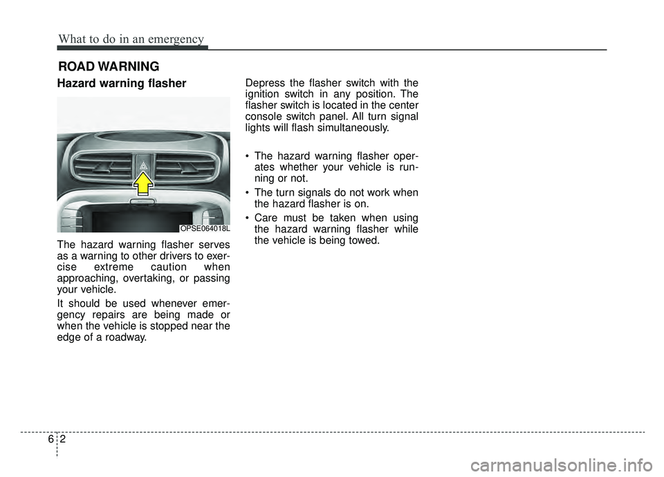
Hazard warning flasher
The hazard warning flasher serves
as a warning to other drivers to exer-
cise extreme caution when
approaching, overtaking, or passing
your vehicle.
It should be used whenever emer-
gency repairs are being made or
when the vehicle is stopped near the
edge of a roadway.Depress the flasher switch with the
ignition switch in any position. The
flasher switch is located in the center
console switch panel. All turn signal
lights will flash simultaneously.
• The hazard warning flasher oper-
ates whether your vehicle is run-
ning or not.
The turn signals do not work when the hazard flasher is on.
Care must be taken when using the hazard warning flasher while
the vehicle is being towed.
OPSE064018L
Page 364 of 455
Maintenance
67
At least monthly:
Check the coolant level in thecoolant reservoir.
Check the operation of all exterior lights, including the stoplights, turn
signals and hazard warning flash-
ers.
Check the inflation pressures of all tires including the spare for tires
that are worn, show uneven wear,
or are damaged.
Check for loose wheel lug nuts.
At least twice a year (i.e., every Spring and Fall):
Check the radiator, heater and air conditioning hoses for leaks or
damage.
Check the windshield washer spray and wiper operation. Clean
the wiper blades with clean cloth
dampened with washer fluid.
Check the headlight alignment.
Check the lap/shoulder belts for wear and function.
At least once a year:
Clean the body and door drainholes.
Lubricate the door hinges and checks, and hood hinges.
Lubricate the door and hood locks and latches.
Lubricate the door rubber weather- strips.
Check the air conditioning system.
Inspect and lubricate the reduction gear linkage and controls.
Clean the battery and terminals.
Check the brake fluid level.
Page 409 of 455
751
Maintenance
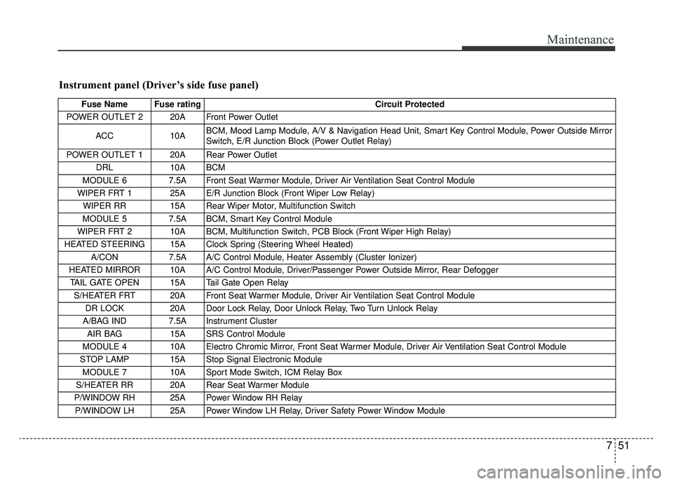
Instrument panel (Driver’s side fuse panel)
Fuse Name Fuse ratingCircuit Protected
POWER OUTLET 2 20A Front Power Outlet
ACC 10A BCM, Mood Lamp Module, A/V & Navigation Head Unit, Smart Key Control Module, Power Outside Mirror
Switch, E/R Junction Block (Power Outlet Relay)
POWER OUTLET 1 20A Rear Power Outlet DRL 10A BCM
MODULE 6 7.5A Front Seat Warmer Module, Driver Air Ventilation Seat Control Module
WIPER FRT 1 25A E/R Junction Block (Front Wiper Low Relay) WIPER RR 15A Rear Wiper Motor, Multifunction Switch
MODULE 5 7.5A BCM, Smart Key Control Module
WIPER FRT 2 10A BCM, Multifunction Switch, PCB Block (Front Wiper High Relay)
HEATED STEERING 15A Clock Spring (Steering Wheel Heated) A/CON 7.5A A/C Control Module, Heater Assembly (Cluster Ionizer)
HEATED MIRROR 10A A/C Control Module, Driver/Passenger Power Outside Mirror, Rear Defogger TAIL GATE OPEN 15A Tail Gate Open Relay S/HEATER FRT 20A Front Seat Warmer Module, Driver Air Ventilation Seat Control Module DR LOCK 20A Door Lock Relay, Door Unlock Relay, Two Turn Unlock Relay
A/BAG IND 7.5A Instrument Cluster AIR BAG 15A SRS Control Module
MODULE 4 10A Electro Chromic Mirror, Front Seat Warmer Module, Driver Air Ventilation Seat Control Module
STOP LAMP 15A Stop Signal Electronic Module MODULE 7 10A Sport Mode Switch, ICM Relay Box
S/HEATER RR 20A Rear Seat Warmer Module
P/WINDOW RH 25A Power Window RH Relay P/WINDOW LH 25A Power Window LH Relay, Driver Safety Power Window Module
Page 416 of 455
Maintenance
58
7
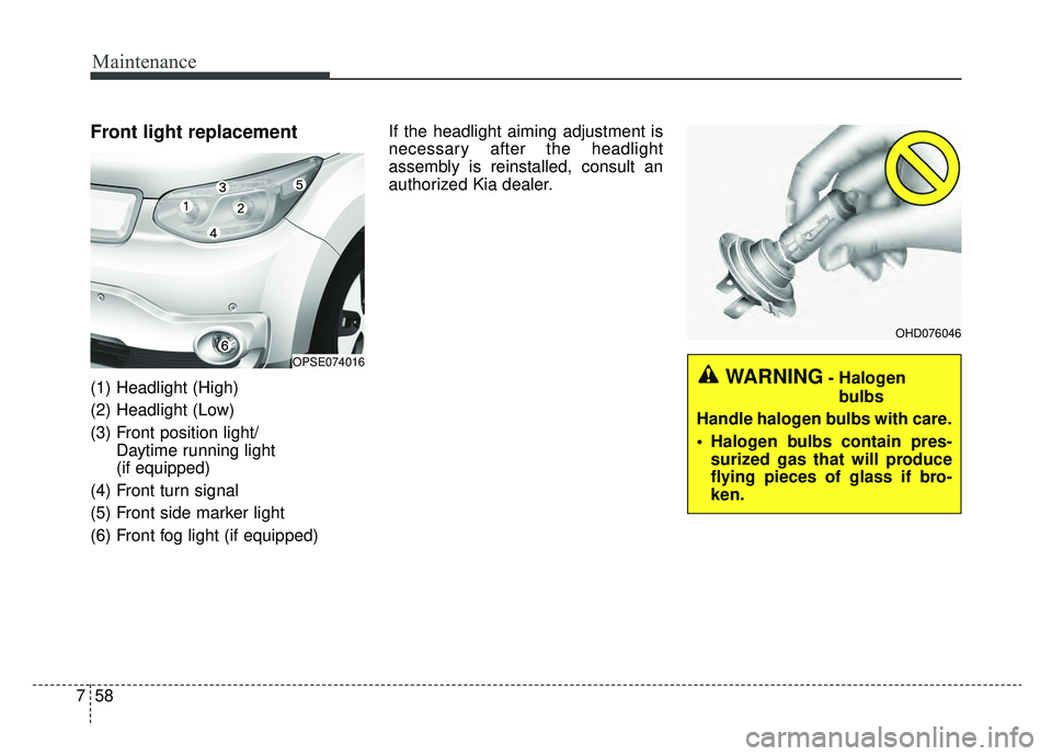
Front light replacement
(1) Headlight (High)
(2) Headlight (Low)
(3) Front position light/
Daytime running light
(if equipped)
(4) Front turn signal
(5) Front side marker light
(6) Front fog light (if equipped) If the headlight aiming adjustment is
necessary after the headlight
assembly is reinstalled, consult an
authorized Kia dealer.
OPSE074016
OHD076046
WARNING- Halogen
bulbs
Handle halogen bulbs with care.
Halogen bulbs contain pres- surized gas that will produce
flying pieces of glass if bro-
ken.
Page 419 of 455
761
Maintenance
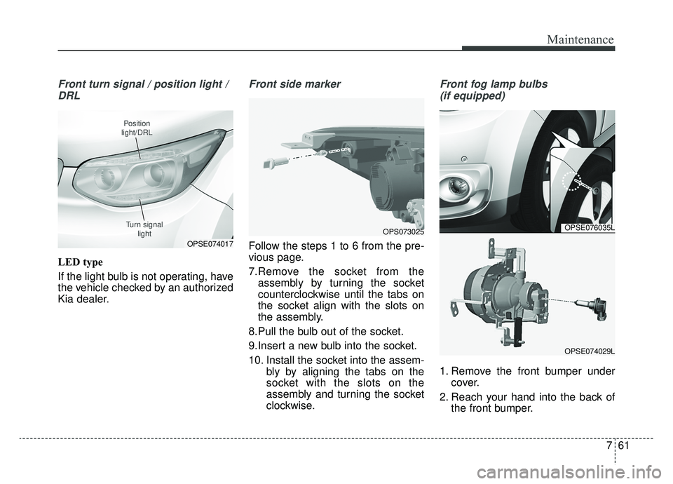
Front turn signal / position light /DRL
LED type
If the light bulb is not operating, have
the vehicle checked by an authorized
Kia dealer.
Front side marker
Follow the steps 1 to 6 from the pre-
vious page.
7.Remove the socket from the assembly by turning the socket
counterclockwise until the tabs on
the socket align with the slots on
the assembly.
8.Pull the bulb out of the socket.
9.Insert a new bulb into the socket.
10. Install the socket into the assem- bly by aligning the tabs on the
socket with the slots on the
assembly and turning the socket
clockwise.
Front fog lamp bulbs
(if equipped)
1. Remove the front bumper under cover.
2. Reach your hand into the back of the front bumper.
OPSE074017
Position
light/DRL
Turn signal light
OPSE076035L
OPSE074029L
OPS073025