fuse KIA VENGA 2016 Owners Manual
[x] Cancel search | Manufacturer: KIA, Model Year: 2016, Model line: VENGA, Model: KIA VENGA 2016Pages: 404, PDF Size: 21.96 MB
Page 12 of 404
Your vehicle at a glance
4
2
INTERIOR OVERVIEW
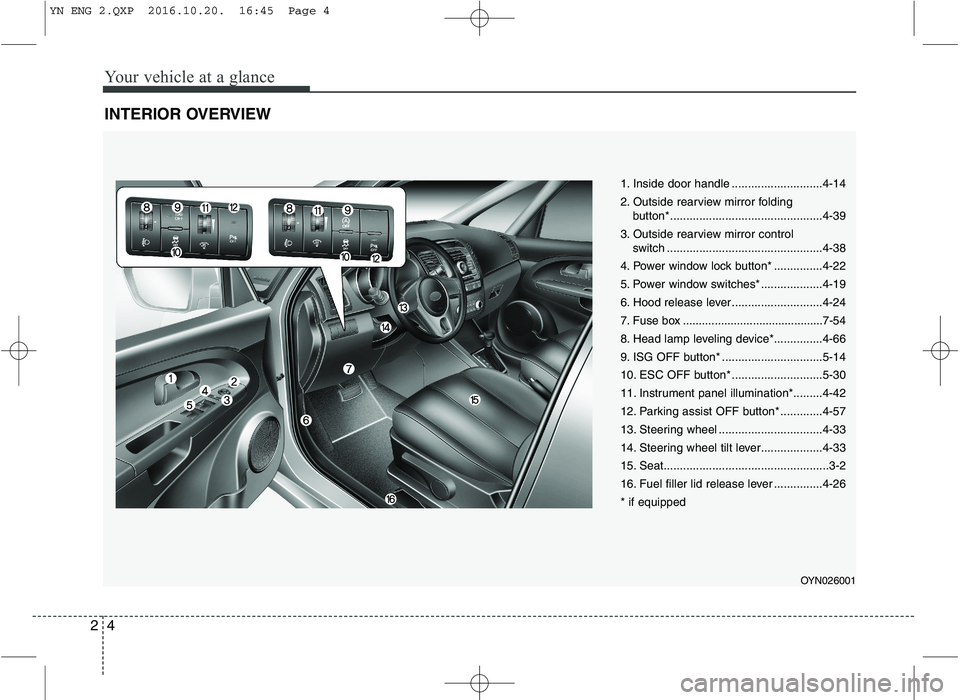
1. Inside door handle ............................4-14
2. Outside rearview mirror folding
button*...............................................4-39
3. Outside rearview mirror control switch ................................................4-38
4. Power window lock button* ...............4-22
5. Power window switches* ...................4-19
6. Hood release lever ............................4-24
7. Fuse box ............................................7-54
8. Head lamp leveling device*...............4-66
9. ISG OFF button* ...............................5-14
10. ESC OFF button* ............................5-30
11. Instrument panel illumination*.........4-42
12. Parking assist OFF button* .............4-57
13. Steering wheel ................................4-33
14. Steering wheel tilt lever...................4-33
15. Seat...................................................3-2
16. Fuel filler lid release lever ...............4-26* if equipped
OYN026001
YN ENG 2.QXP 2016.10.20. 16:45 Page 4
Page 14 of 404
Your vehicle at a glance
6
2
ENGINE COMPARTMENT
OYN025003/OYN075101
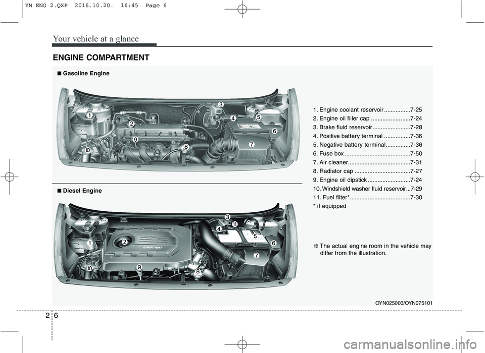
1. Engine coolant reservoir ................7-25
2. Engine oil filler cap ........................7-24
3. Brake fluid reservoir .......................7-28
4. Positive battery terminal ................7-36
5. Negative battery terminal...............7-36
6. Fuse box ........................................7-50
7. Air cleaner......................................7-31
8. Radiator cap ..................................7-27
9. Engine oil dipstick ..........................7-24
10. Windshield washer fluid reservoir...7-29
11. Fuel filter*.....................................7-30 * if equipped
■■
Gasoline Engine
❈ The actual engine room in the vehicle may
differ from the illustration.
■■ Diesel Engine
YN ENG 2.QXP 2016.10.20. 16:45 Page 6
Page 58 of 404
Safety features of your vehicle
44
3
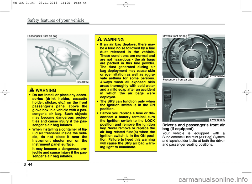
Driver's and passenger's front air
bag (if equipped)
Your vehicle is equipped with a
Supplemental Restraint (Air Bag) System
and lap/shoulder belts at both the driver
and passenger seating positions.
WARNING
If an air bag deploys, there may be a loud noise followed by a fine
dust released in the vehicle.These conditions are normal and
are not hazardous - the air bags
are packed in this fine powder.
The dust generated during air
bag deployment may cause skin
or eye irritation as well as aggra-
vate asthma for some persons.
Always wash all exposed skin
areas thoroughly with cold waterand a mild soap after an accident
in which the air bags were
deployed.
The SRS can function only when the ignition switch is in the ONposition.
Before you replace a fuse or dis- connect a battery terminal, turn
the ignition switch to the LOCK
position and remove the ignition
key. Never remove or replace the
air bag related fuse(s) when the
ignition switch is in the ON posi-
tion. Failure to heed this warning
will cause the SRS air bag warn-
ing light to illuminate.
OYN039024
OYN039025
Driver’s front air bag
Passenger’s front air bag
WARNING
Do not install or place any acces- sories (drink holder, cassette
holder, sticker, etc.) on the front
passenger's panel above the
glove box in a vehicle with a pas-
senger's air bag. Such objects
may become dangerous projec-
tiles and cause injury if the pas-
senger's air bag inflates.
When installing a container of liq- uid air freshener inside the vehi-
cle, do not place it near the
instrument cluster nor on the
instrument panel surface.
It may become a dangerous pro-
jectile and cause injury if the pas-
senger's air bag inflates.
B240B05L
Passenger’s front air bag
YN ENG 3.QXP 28.11.2016 16:05 Page 44
Page 96 of 404
Features of your vehicle
22
4
✽✽
NOTICE
The automatic reverse feature for the
window is only active when the “auto
up” feature is used by fully pulling up
the switch. The automatic reverse fea-
ture will not operate if the window is
raised using the halfway position on the
power window switch.
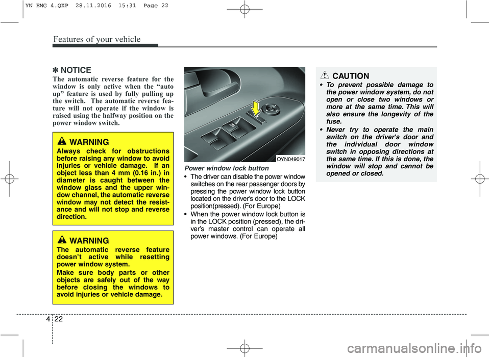
Power window lock button
The driver can disable the power window switches on the rear passenger doors by
pressing the power window lock button
located on the driver's door to the LOCK
position(pressed). (For Europe)
When the power window lock button is
in the LOCK position (pressed), the dri-
ver’s master control can operate all
power windows. (For Europe)
CAUTION
To prevent possible damage to
the power window system, do notopen or close two windows ormore at the same time. This will
also ensure the longevity of thefuse.
Never try to operate the main switch on the driver's door andthe individual door window
switch in opposing directions atthe same time. If this is done, the window will stop and cannot beopened or closed.
WARNING
Always check for obstructions
before raising any window to avoid
injuries or vehicle damage. If anobject less than 4 mm (0.16 in.) indiameter is caught between the
window glass and the upper win-
dow channel, the automatic reverse
window may not detect the resist-
ance and will not stop and reversedirection.
OYN049017
WARNING
The automatic reverse feature doesn’t active while resetting
power window system.
Make sure body parts or other
objects are safely out of the way
before closing the windows to
avoid injuries or vehicle damage.
YN ENG 4.QXP 28.11.2016 15:31 Page 22
Page 106 of 404
Features of your vehicle
32
4
Resetting the sunroof
Whenever the vehicle battery is discon-
nected or discharged, you must reset
your sunroof system as follows:
1. Turn the ignition switch to the ON
position.
2. Open the roller blind.
3. Close the sunroof.
4. Release the sunroof control lever.
5. Push the sunroof control lever forward in the direction of close (about 10 sec-
onds) until the sunroof is moved a lit-
tle. Then, release the lever.
6. Push the sunroof control lever forward in the direction of close until the sun-
roof operates as follows;
TILT OPEN �SLIDE OPEN �
SLIDE CLOSE
Then, release the lever.
When this is complete, the sunroof sys- tem has been reset.CAUTION
If the sunroof is not reset when the vehicle battery is disconnected ordischarged, or related fuse is blown, the sunroof may operate
improperly.
YN ENG 4.QXP 28.11.2016 15:32 Page 32
Page 223 of 404
513
Driving your vehicle
✽✽
NOTICE
If the battery is weak or the smart key does not work correctly, you can start
the engine by pressing the engine
start/stop button with the smart key.
When the stop lamp fuse is blown, you
can't start the engine normally. Replace
the fuse with a new one. If it is not pos-
sible, you can start the engine by press-
ing the ENGINE START/STOP button
for 10 seconds while it is in the ACC
position. The engine can start without
depressing the brake pedal. But for
your safety always depress the brake
pedal before starting the engine.
(Automatic transaxle vehicle)
When the clutch switch is damage, you
can not start the engine normally.
Replace the clutch switch with a new
one. If it is not possible you can start
the engine by pressing the ENGINE
START/STOP for 10 seconds with
pressing the brake pedal. (Manual
transaxle vehi cle)
CAUTION
Do not press the ENGINE START/
STOP button for more than 10 sec-
onds except when the stop lampfuse is blown.
CAUTION
If the engine stalls while the vehicle
is in motion, do not attempt to movethe shift lever to the P (Park) posi- tion. If the traffic and road condi-
tions permit, you may put the shiftlever in the N (Neutral) positionwhile the vehicle is still moving andpress the ENGINE START/STOP
button in an attempt to restart the engine.
YN ENG 5.QXP 9/5/2016 4:31 PM Page 13
Page 304 of 404
7
Engine compartment / 7-2
Maintenance services / 7-3
Owner maintenance / 7-5
Scheduled maintenance service / 7-7
Explanation of scheduled maintenance items / 7-20
Engine oil / 7-24
Engine coolant / 7-25
Brake/clutch fluid / 7-28
Washer fluid / 7-29
Parking brake / 7-29
Fuel filter / 7-30
Air cleaner / 7-31
Climate control air filter / 7-32
Wiper blades / 7-34
Battery / 7-36
Tires and wheels / 7-40
Fuses / 7-50
Light bulbs / 7-62
Appearance care / 7-71
Emission control system / 7-78
Maintenance
YN ENG 7.QXP 9/5/2016 4:35 PM Page 1
Page 305 of 404
Maintenance
2
7
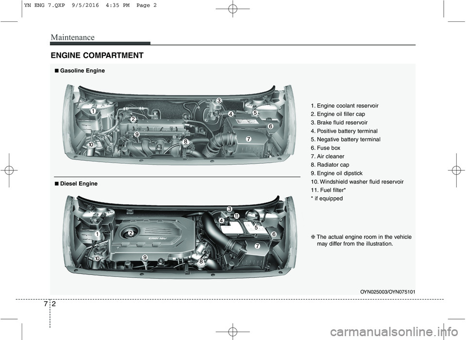
ENGINE COMPARTMENT
OYN025003/OYN075101
1. Engine coolant reservoir
2. Engine oil filler cap
3. Brake fluid reservoir
4. Positive battery terminal
5. Negative battery terminal
6. Fuse box
7. Air cleaner
8. Radiator cap
9. Engine oil dipstick
10. Windshield washer fluid reservoir
11. Fuel filter* * if equipped
■■
Gasoline Engine
❈ The actual engine room in the vehicle
may differ from the illustration.
■■ Diesel Engine
YN ENG 7.QXP 9/5/2016 4:35 PM Page 2
Page 353 of 404
Maintenance
50
7
FUSES
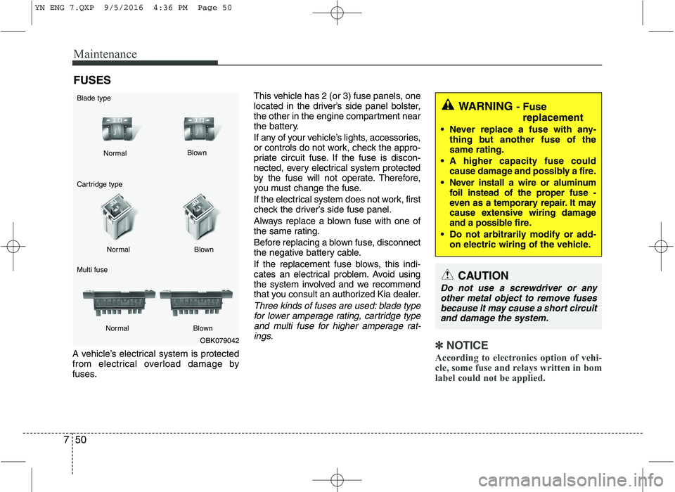
A vehicle’s electrical system is protected
from electrical overload damage by
fuses. This vehicle has 2 (or 3) fuse panels, one
located in the driver’s side panel bolster,
the other in the engine compartment near
the battery.
If any of your vehicle’s lights, accessories,
or controls do not work, check the appro-
priate circuit fuse. If the fuse is discon-
nected, every electrical system protected
by the fuse will not operate. Therefore,
you must change the fuse.
If the electrical system does not work, first
check the driver’s side fuse panel.
Always replace a blown fuse with one of
the same rating.
Before replacing a blown fuse, disconnect
the negative battery cable.
If the replacement fuse blows, this indi-
cates an electrical problem. Avoid using
the system involved and we recommend
that you consult an authorized Kia dealer.
Three kinds of fuses are used: blade type
for lower amperage rating, cartridge typeand multi fuse for higher amperage rat-ings.
✽✽ NOTICE
According to electronics option of vehi-
cle, some fuse and relays written in bom
label could not be applied.OBK079042
Normal
Normal
Cartridge type Multi fuse Blown
Blown
Normal Blown
WARNING - Fuse
replacement
Never replace a fuse with any- thing but another fuse of the same rating.
A higher capacity fuse could cause damage and possibly a fire.
Never install a wire or aluminum foil instead of the proper fuse -
even as a temporary repair. It may
cause extensive wiring damage
and a possible fire.
Do not arbitrarily modify or add- on electric wiring of the vehicle.
CAUTION
Do not use a screwdriver or any
other metal object to remove fusesbecause it may cause a short circuit and damage the system.
Blade type
YN ENG 7.QXP 9/5/2016 4:36 PM Page 50
Page 354 of 404
751
Maintenance
✽✽NOTICE
The actual fuse/relay panel label may
differ from equipped items.
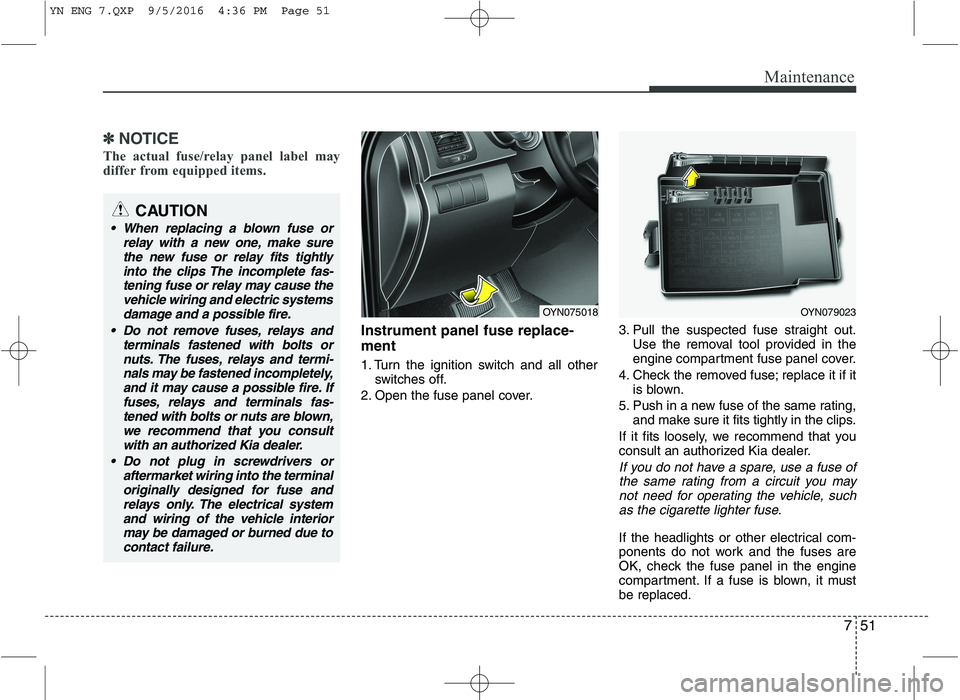
Instrument panel fuse replace- ment
1. Turn the ignition switch and all other switches off.
2. Open the fuse panel cover. 3. Pull the suspected fuse straight out.
Use the removal tool provided in the
engine compartment fuse panel cover.
4. Check the removed fuse; replace it if it is blown.
5. Push in a new fuse of the same rating, and make sure it fits tightly in the clips.
If it fits loosely, we recommend that you
consult an authorized Kia dealer.
If you do not have a spare, use a fuse of the same rating from a circuit you may not need for operating the vehicle, suchas the cigarette lighter fuse.
If the headlights or other electrical com-
ponents do not work and the fuses are
OK, check the fuse panel in the engine
compartment. If a fuse is blown, it mustbe replaced.
OYN079023OYN075018
CAUTION
When replacing a blown fuse or relay with a new one, make sure
the new fuse or relay fits tightly into the clips The incomplete fas-tening fuse or relay may cause the
vehicle wiring and electric systemsdamage and a possible fire.
Do not remove fuses, relays and terminals fastened with bolts ornuts. The fuses, relays and termi-
nals may be fastened incompletely,and it may cause a possible fire. Iffuses, relays and terminals fas-tened with bolts or nuts are blown,
we recommend that you consultwith an authorized Kia dealer.
Do not plug in screwdrivers or aftermarket wiring into the terminaloriginally designed for fuse and
relays only. The electrical systemand wiring of the vehicle interiormay be damaged or burned due to
contact failure.
YN ENG 7.QXP 9/5/2016 4:36 PM Page 51