battery Lancia Delta 2012 Owner handbook (in English)
[x] Cancel search | Manufacturer: LANCIA, Model Year: 2012, Model line: Delta, Model: Lancia Delta 2012Pages: 295, PDF Size: 8.29 MB
Page 183 of 295

3
STARTING AND DRIVING181
HANDBRAKE
The handbrake lever is located between the two front
seats.
Pull the lever upwards to operate the handbrake, until
the vehicle is braked.
The car should be braked after a few clicks
of the lever; if it is not, contact a Lancia
Dealership to have it adjusted.
When the handbrake is on and the ignition key is at MAR,
the instrument panel warning light xwill come on.
Proceed as follows to release the handbrake:
❍slightly lift the handbrake and press release button
A-fig. 1;
❍keep button A pressed and lower the lever. The warn-
ing light xon the instrument panel will turn off.
Press the brake pedal when carrying out this operation
to prevent the car from moving accidentally. PARKING THE VEHICLE
Proceed as follows:
❍stop the engine and engage the handbrake;
❍engage a gear (on a slope, engage first gear if the car
is facing uphill or reverse if it is facing downhill) and
leave the wheels steered.
If the car is parked on a steep slope, it is also advisable
to block the wheels with a wedge or stone.
Do not leave the ignition key turned to MAR to prevent
draining the battery. Always remove the key when you
leave the car.
Never leave children in the unattended car. Always re-
move the ignition key when leaving the car and take it
out with you.
fig. 1L0E0072m
Page 189 of 295
3
STARTING AND DRIVING187
Keep your speed down when snow chains are
fitted. Do not exceed 50 km/h. Avoid pot-
holes, steps and pavements and also avoid
driving long distances on roads not covered with
snow in order to prevent damaging the car and the
roadbed.
SNOW CHAINS
The use of snow chains should be in compliance with lo-
cal regulations.
The snow chains may be applied only onto the front
wheel tyres (drive wheels).
Check the tension of the snow chains after the first few
metres have been driven.
IMPORTANT Snow chains cannot be fitted to the space-
saver spare wheel. So, if a front (drive) wheel is punc-
tured and chains are needed, a rear wheel should be fit-
ted to the front of the car and the space-saving spare
wheel should be fitted to the rear. This way with two nor-
mal drive wheels, snow chains can be fitted to them to
solve an emergency.
CAR INACTIVITY
If the car is to be left inactive for longer than a month,
the following precautions should be followed:
❍park the car in a covered, dry and, if possible, well-
ventilated place;
❍engage a gear;
❍check that the handbrake is not engaged;
❍disconnect the negative battery terminal (for versions
with Start&Stop system refer to the paragraph
“Start&Stop system” in chapter “1”);
❍clean and protect the painted parts of the vehicle with
protective wax;
❍clean and protect the shiny metal parts using special
compounds commercially available;
❍sprinkle talcum powder on the rubber windscreen and
rear window wiper blades and lift them off the glass;
❍open the windows slightly;
❍cover the car with a fabric or perforated plastic sheet.
Do not use sheets of non-perforated plastic as they
do not allow moisture on the car body to evaporate;
❍inflate tyres to a pressure of +0.5 bar above the nor-
mal specified pressure and check regularly;
❍do not drain the engine cooling system.
Page 191 of 295
4
IN AN EMERGENCY189
Engine starting ....................................................................... 190
Quick tyre repair kit Fix&Go Automatic ................................. 192
Replacing a wheel ................................................................... 199
Changing a bulb ..................................................................... 206
Replacing exterior bulbs .......................................................... 210
Replacing an interior bulb ....................................................... 215
Replacing fuses ....................................................................... 219
Battery recharging .................................................................. 226
Jacking the car ........................................................................ 227
Towing the car ........................................................................ 227
In an emergency we recommend that you call the freephone number
found in the Warranty Booklet.
It is also possible to go to the www.lancia.com website
to find the closest Lancia Dealership.
Page 192 of 295

190IN AN EMERGENCY
ENGINE STARTING
Go to a Lancia Dealership immediately if instrument
panel warning light
Yremains on constantly.
JUMP STARTING fig. 1
If the battery is flat, the engine may be started using an
auxiliary battery with the same capacity or a little higher
than the flat one.
fig. 1L0E0074m
Strictly avoid using a rapid battery charger
for jump starting: this could damage the
electronic systems and the engine fuel sup-
ply and ignition control units.
This starting procedure must be carried out
by expert personnel as incorrect manoeu-
vres can cause electrical discharges of con-
siderable intensity. Furthermore, battery fluid is
poisonous and corrosive: avoid contact with your
skin and eyes. Keep naked flames away from the
battery. No smoking. Do not cause sparks.
Page 193 of 295
IN AN EMERGENCY191
4
Proceed as follows to start the car:
❍connect the positive terminals (+ sign close to the ter-
minal) of both batteries using a lead;
❍with a second lead, connect the negative terminal (–)
of the auxiliary battery to an earthing point E
on the
engine or the gearbox of the car to be started;
❍start the engine;
❍when the engine has been started, follow the sequence
above in reverse order to remove the leads.
For versions with Start&Stop system, in case of starting
by booster battery, refer to the paragraph “Start&Stop
system” in the chapter “1”.
If after a few attempts the engine does not start, do not
persist but contact a Lancia Dealership.
IMPORTANT Do not directly connect the negative termi-
nals of the two batteries: any sparks may ignite the explo-
sive gas which could come out of the battery. If the auxil-
iary battery is installed on another car, prevent any contact
between metal parts of the cars and the flat battery.BUMP STARTING
Never bump start the engine by pushing, towing or dri-
ving downhill.
This could cause a flow of fuel into the catalytic converter
and damage it beyond repair.
IMPORTANT Remember that the brake servo and elec-
trical power steering system (where provided) are not op-
erational until the engine is started, a greater effort will
therefore be required to press the brake pedal or turn the
steering wheel.
Page 223 of 295

IN AN EMERGENCY221
4
Engine compartment fuse box fig. 39 and 40
A second fuse box is located on the right side of the en-
gine compartment, next to the battery. To access this fuse
box release the side tabs and remove cover L. The ID
number of the electrical component corresponding to
each fuse can be found on the back of the cover.
fig. 39L0E0088mfig. 38aL0E0211m
If you need to wash the engine compartment,
take care not to directly hit the engine com-
partment fuse box with the jet of water.
Additional fuses (1.4 Turbo Multi Air versions)
On the 1.4 Turbo Multi Air versions there are four addi-
tional fuses (fig. 38a) next to the dashboard junction unit.
Page 227 of 295
IN AN EMERGENCY225
4
38a
38a
38a
38a
40
40
40
40
40
40
40
40
40
2
42
42
42
42
42
42(P038)
(P036)
(P037)
(P039)
F08
F09
F10
F14
F15
F19
F30
F85
F87
F1
F2
F3
F6
F4
F4
F510
5
5
5
40
30
15
15
30
7.5
15
15
5
30
30
10
10
15
20
10
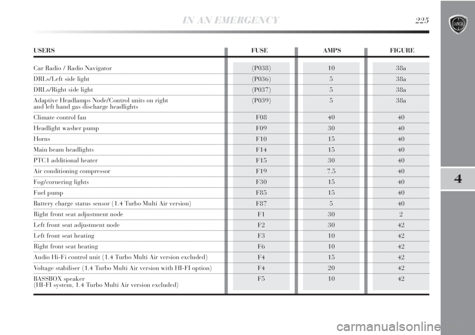
USERS FUSE AMPS FIGURE
Car Radio / Radio Navigator
DRLs/Left side light
DRLs/Right side light
Adaptive Headlamps Node/Control units on right
and left hand gas discharge headlights
Climate control fan
Headlight washer pump
Horns
Main beam headlights
PTC1 additional heater
Air conditioning compressor
Fog/cornering lights
Fuel pump
Battery charge status sensor (1.4 Turbo Multi Air version)
Right front seat adjustment node
Left front seat adjustment node
Left front seat heating
Right front seat heating
Audio Hi-Fi control unit (1.4 Turbo Multi Air version excluded)
Voltage stabiliser (1.4 Turbo Multi Air version with HI-FI option)
BASSBOX speaker
(HI-FI system, 1.4 Turbo Multi Air version excluded)
Page 228 of 295

226IN AN EMERGENCY
BATTERY RECHARGING
IMPORTANT The battery recharging procedure is given
as information only. You are advised to go to a Lancia
Dealership to have this operation performed.
Charging should be slow at a low ampere rating for ap-
proximately 24 hours. Charging for a longer time may
damage the battery.
VERSIONS WITHOUT Start&Stop SYSTEM
(for versions/markets, where provided)
Charge the battery as follows:
❍disconnect the negative battery terminal;
❍connect the charger leads to the battery terminals, ob-
serving the polarity;
❍turn on the charger;
❍when you have finished, turn the charger off before
disconnecting the battery;
❍reconnect the negative battery terminal.VERSIONS WITH Start&Stop SYSTEM fig. 43
(for versions/markets, where provided)
To charge, proceed as follows:
❍detach the connector A (by pressing button B) from
sensor C for monitoring the status of the battery in-
stalled on the negative battery pole D;
fig. 43L0E0199m
Page 229 of 295

IN AN EMERGENCY227
4
Battery fluid is poisonous and corrosive:
avoid contact with your skin and eyes. The
battery recharging operation must be per-
formed in a ventilated place, away from naked
flames or possible sources of sparks to avoid the
risk of explosion and fire.
Don’t try to recharge a frozen battery: If the
battery was frozen, have it inspected by
skilled personnel before recharging to check
that the internal elements are not damaged and that
the casing is not cracked, which causes the risk of
leakage of poisonous, corrosive acid.
JACKING THE CAR
If the car is to be lifted, go to a Lancia Dealership which
is equipped with the arm hoist or workshop lift.
TOWING THE CAR
The tow ring, which is provided with the car, is housed
in the tool box, under the boot mat.
FASTENING THE TOW RING fig. 44-45
Proceed as follows:
❍release cap A;
❍take the tow ring B from its housing in the tool sup-
port;
❍screw the ring onto the rear or front threaded pin.
fig. 44L0E0297m
❍connect the positive cable to the positive battery ter-
minal E and the negative terminal to the sensor D as
shown in the figure;
❍turn on the charger. Turn the device off after recharg-
ing;
❍after having disconnected the recharging device, re-
connect the connector A to the sensor C as shown in
the figure.
Page 231 of 295
5
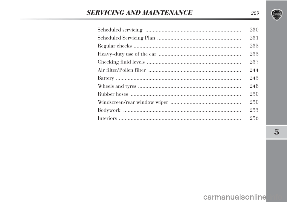
SERVICING AND MAINTENANCE229
Scheduled servicing ................................................................. 230
Scheduled Servicing Plan ......................................................... 231
Regular checks ......................................................................... 235
Heavy-duty use of the car ........................................................ 235
Checking fluid levels ................................................................ 237
Air filter/Pollen filter ............................................................... 244
Battery ..................................................................................... 245
Wheels and tyres ...................................................................... 248
Rubber hoses ........................................................................... 250
Windscreen/rear window wiper ................................................ 250
Bodywork ................................................................................ 253
Interiors ................................................................................... 256