engine Lancia Flavia 2012 Owner handbook (in English)
[x] Cancel search | Manufacturer: LANCIA, Model Year: 2012, Model line: Flavia, Model: Lancia Flavia 2012Pages: 233, PDF Size: 2.61 MB
Page 118 of 233
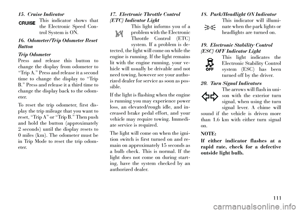
15. Cruise IndicatorThis indicator shows that
the Electronic Speed Con-
trol System is ON.
16. Odometer/Trip Odometer Reset
Button
Trip Odometer
Press and release this button to
change the display from odometer to
“Trip A.” Press and release it a second
time to change the display to “Trip
B.” Press and release it a third time to
change the display back to the odom-
eter.
To reset the trip odometer, first dis-
play the trip mileage that you want to
reset, “Trip A” or “Trip B.” Then push
and hold the button (approximately
2 seconds) until the display resets to
0 miles (km). The odometer must be
in Trip Mode to reset the trip odom-
eter. 17. Electronic Throttle Control
(ETC) Indicator Light
This light informs you of a
problem with the Electronic
Throttle Control (ETC)
system. If a problem is de-
tected, the light will come on while the
engine is running. If the light remains
lit with the engine running, your ve-
hicle will usually be drivable and not
need towing, however see your autho-
rized dealer for service as soon as pos-
sible.
If the light is flashing when the engine
is running you may experience power
loss, an elevated/rough idle, and in-
creased brake pedal effort, and your
vehicle may require towing. Immedi-
ate service is required.
The light will come on when the igni-
tion switch is first turned on and re-
main on approximately 15 seconds as
a bulb check. This is normal. If the
light does not come on during start-
ing, have the system checked by an
authorized dealer. 18. Park/Headlight ON Indicator
This indicator will illumi-
nate when the park lights or
headlights are turned on.
19. Electronic Stability Control
(ESC) OFF Indicator Light This light indicates the
Electronic Stability Control
system (ESC) has been
turned off by the driver.
20. Turn Signal Indicators The arrows will flash in uni-
son with the exterior turn
signal, when using the turn
signal lever. A chime will
sound if the vehicle is driven more
than 1.6 km with either turn signal
on.
NOTE:
If either indicator flashes at a
rapid rate, check for a defective
outside light bulb.
111
Page 119 of 233
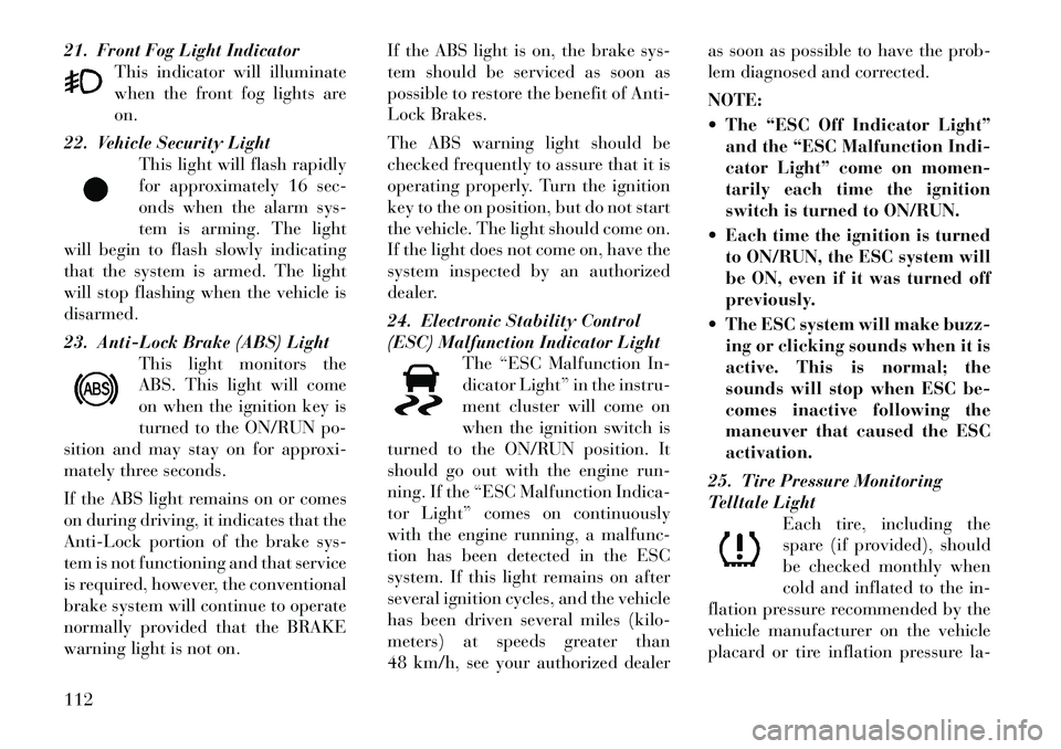
21. Front Fog Light IndicatorThis indicator will illuminate
when the front fog lights are
on.
22. Vehicle Security Light This light will flash rapidly
for approximately 16 sec-
onds when the alarm sys-
tem is arming. The light
will begin to flash slowly indicating
that the system is armed. The light
will stop flashing when the vehicle is
disarmed.
23. Anti-Lock Brake (ABS) Light This light monitors the
ABS. This light will come
on when the ignition key is
turned to the ON/RUN po-
sition and may stay on for approxi-
mately three seconds.
If the ABS light remains on or comes
on during driving, it indicates that the
Anti-Lock portion of the brake sys-
tem is not functioning and that service
is required, however, the conventional
brake system will continue to operate
normally provided that the BRAKE
warning light is not on. If the ABS light is on, the brake sys-
tem should be serviced as soon as
possible to restore the benefit of Anti-
Lock Brakes.
The ABS warning light should be
checked frequently to assure that it is
operating properly. Turn the ignition
key to the on position, but do not start
the vehicle. The light should come on.
If the light does not come on, have the
system inspected by an authorized
dealer.
24. Electronic Stability Control
(ESC) Malfunction Indicator Light
The “ESC Malfunction In-
dicator Light” in the instru-
ment cluster will come on
when the ignition switch is
turned to the ON/RUN position. It
should go out with the engine run-
ning. If the “ESC Malfunction Indica-
tor Light” comes on continuously
with the engine running, a malfunc-
tion has been detected in the ESC
system. If this light remains on after
several ignition cycles, and the vehicle
has been driven several miles (kilo-
meters) at speeds greater than
48 km/h, see your authorized dealer as soon as possible to have the prob-
lem diagnosed and corrected.
NOTE:
The “ESC Off Indicator Light”
and the “ESC Malfunction Indi-
cator Light” come on momen-
tarily each time the ignition
switch is turned to ON/RUN.
Each time the ignition is turned to ON/RUN, the ESC system will
be ON, even if it was turned off
previously.
The ESC system will make buzz- ing or clicking sounds when it is
active. This is normal; the
sounds will stop when ESC be-
comes inactive following the
maneuver that caused the ESC
activation.
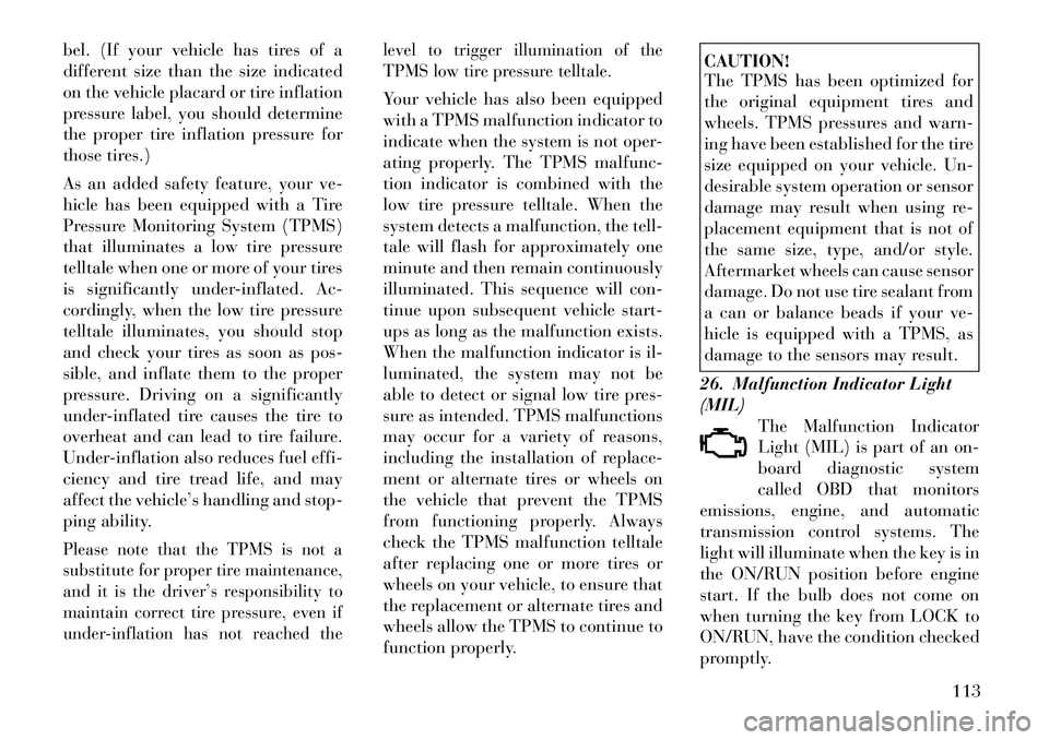
25. Tire Pressure Monitoring
Telltale Light Each tire, including the
spare (if provided), should
be checked monthly when
cold and inflated to the in-
flation pressure recommended by the
vehicle manufacturer on the vehicle
placard or tire inflation pressure la-112
Page 120 of 233
bel. (If your vehicle has tires of a
different size than the size indicated
on the vehicle placard or tire inflation
pressure label, you should determine
the proper tire inflation pressure for
those tires.)
As an added safety feature, your ve-
hicle has been equipped with a Tire
Pressure Monitoring System (TPMS)
that illuminates a low tire pressure
telltale when one or more of your tires
is significantly under-inflated. Ac-
cordingly, when the low tire pressure
telltale illuminates, you should stop
and check your tires as soon as pos-
sible, and inflate them to the proper
pressure. Driving on a significantly
under-inflated tire causes the tire to
overheat and can lead to tire failure.
Under-inflation also reduces fuel effi-
ciency and tire tread life, and may
affect the vehicle’s handling and stop-
ping ability.Please note that the TPMS is not a
substitute for proper tire maintenance,
and it is the driver’s responsibility to
maintain correct tire pressure, even if
under-inflation has not reached thelevel to trigger illumination of the
TPMS low tire pressure telltale.
Your vehicle has also been equipped
with a TPMS malfunction indicator to
indicate when the system is not oper-
ating properly. The TPMS malfunc-
tion indicator is combined with the
low tire pressure telltale. When the
system detects a malfunction, the tell-
tale will flash for approximately one
minute and then remain continuously
illuminated. This sequence will con-
tinue upon subsequent vehicle start-
ups as long as the malfunction exists.
When the malfunction indicator is il-
luminated, the system may not be
able to detect or signal low tire pres-
sure as intended. TPMS malfunctions
may occur for a variety of reasons,
including the installation of replace-
ment or alternate tires or wheels on
the vehicle that prevent the TPMS
from functioning properly. Always
check the TPMS malfunction telltale
after replacing one or more tires or
wheels on your vehicle, to ensure that
the replacement or alternate tires and
wheels allow the TPMS to continue to
function properly.
CAUTION!
The TPMS has been optimized for
the original equipment tires and
wheels. TPMS pressures and warn-
ing have been established for the tire
size equipped on your vehicle. Un-
desirable system operation or sensor
damage may result when using re-
placement equipment that is not of
the same size, type, and/or style.
Aftermarket wheels can cause sensor
damage. Do not use tire sealant from
a can or balance beads if your ve-
hicle is equipped with a TPMS, as
damage to the sensors may result.
26. Malfunction Indicator Light
(MIL) The Malfunction Indicator
Light (MIL) is part of an on-
board diagnostic system
called OBD that monitors
emissions, engine, and automatic
transmission control systems. The
light will illuminate when the key is in
the ON/RUN position before engine
start. If the bulb does not come on
when turning the key from LOCK to
ON/RUN, have the condition checked
promptly.
113
Page 121 of 233
Certain conditions, such as a loose or
missing gas cap, poor fuel quality,
etc., may illuminate the light after
engine start. The vehicle should be
serviced if the light stays on through
several of your typical driving cycles.
In most situations, the vehicle will
drive normally and will not require
towing.CAUTION!
Prolonged driving with the MIL on
could cause damage to the engine
control system. It also could affect
fuel economy and drivability. If the
MIL is flashing, severe catalytic con-
verter damage and power loss will
soon occur. Immediate service is re-
quired.
WARNING!
A malfunctioning catalytic con-
verter, as referenced above, can
reach higher temperatures than in
normal operating conditions. This
can cause a fire if you drive slowly or
park over flammable substances
such as dry plants, wood, cardboard,
etc. This could result in death or
serious injury to the driver, occu-
pants or others.
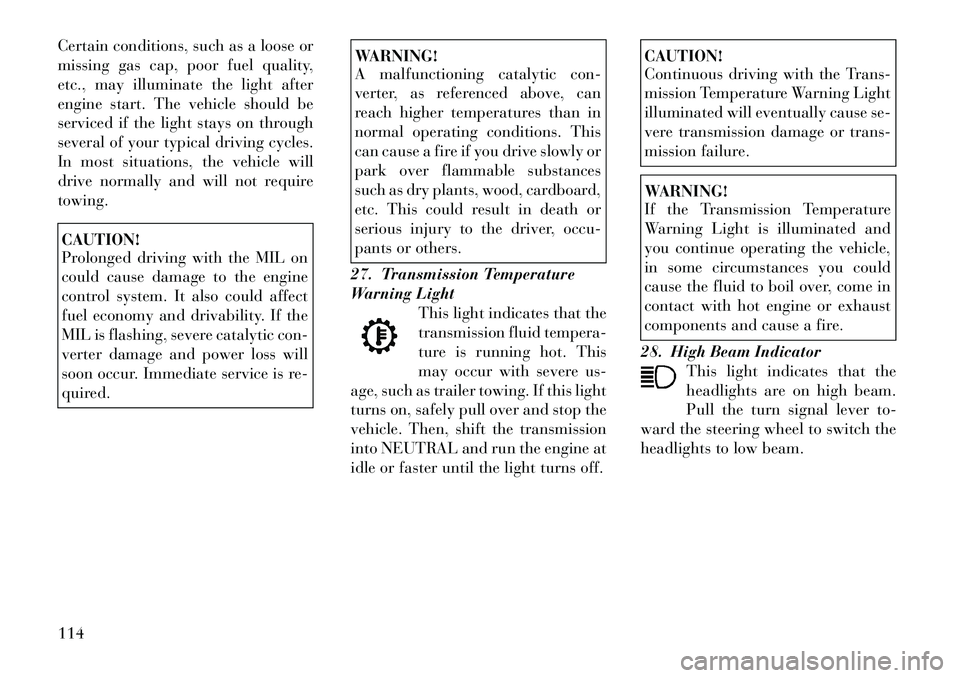
27. Transmission Temperature
Warning Light This light indicates that the
transmission fluid tempera-
ture is running hot. This
may occur with severe us-
age, such as trailer towing. If this light
turns on, safely pull over and stop the
vehicle. Then, shift the transmission
into NEUTRAL and run the engine at
idle or faster until the light turns off.
CAUTION!
Continuous driving with the Trans-
mission Temperature Warning Light
illuminated will eventually cause se-
vere transmission damage or trans-
mission failure.WARNING!
If the Transmission Temperature
Warning Light is illuminated and
you continue operating the vehicle,
in some circumstances you could
cause the fluid to boil over, come in
contact with hot engine or exhaust
components and cause a fire.
28. High Beam Indicator This light indicates that the
headlights are on high beam.
Pull the turn signal lever to-
ward the steering wheel to switch the
headlights to low beam.
114
Page 124 of 233
Check TPM System (with a singlechime) Refer to "Tire Pressure
Monitoring System" in "Starting
and Operating".
OIL CHANGE REQUIRED
Your vehicle is equipped with an en-
gine oil change indicator system. The
“Oil Change Required” message will
flash in the EVIC display for approxi-
mately five seconds after a single
chime has sounded to indicate the
next scheduled oil change interval.
The engine oil change indicator sys-
tem is duty cycle based, which means
the engine oil change interval may
fluctuate dependent upon your per-
sonal driving style.
Unless reset, this message will con-
tinue to display each time you cycle
the ignition to the ON/RUN position.
EVIC MAIN MENU
To step to each main menu feature
press and release the MENU button
once for each step. A step from the last
item in the list will cause the first item
in the feature list to be displayed. The
following features are in the Main
menu: Compass, Outside Temperature,
Audio Information (if radio is on)
display
Average Fuel Economy
Distance to Empty
Tire Pressure Status display
Elapsed Time
EVIC Units Selection
System Status
Personal Settings
NOTE:
For features in the EVIC that can
be reset (Average Fuel Economy
and Elapsed Time), the EVIC
prompts a reset with a SELECT
button graphic and the word RE-
SET next to it.
When the SELECT button is
pressed, the selected feature will
reset and RESET ALL will display
next to the SELECT button
graphic. Pressing SELECT a sec-
ond time will reset both Average
Fuel Economy and Elapsed Time.
After three seconds without press-
ing SELECT, RESET ALL will re- turn to RESET and only the se-
lected feature will have been reset.
COMPASS DISPLAY
COMPASS Button
The compass heading indi-
cates the direction the ve-
hicle is facing. Press and re-
lease the compass button to
display one of eight compass head-
ings, the outside temperature, and au-
dio information (if the radio is on) if
the EVIC display is not already dis-
playing this screen.
NOTE:
The system will display the last
known outside temperature when
starting the vehicle and may need
to be driven several minutes before
the updated temperature is dis-
played. Engine temperature can
also affect the displayed tempera-
ture; therefore, temperature read-
ings are not updated when the ve-
hicle is not moving.
117
Page 125 of 233
If the vehicle is equipped with the
manufacturers gps (Navigation Ra-
dio), the NAV system will provide the
compass direction, and the variance
and calibration menus will be un-
available. The compass will perform
accurately, based on GPS signals in-
stead of the Earth’s magnetic field.
Automatic Compass Calibration
This compass is self-calibrating,
which eliminates the need to calibrate
the compass manually. When the ve-
hicle is new, the compass may appear
erratic and the EVIC will flash the
“CAL” indicator until the compass is
calibrated. You may calibrate the
compass by completing one or more
360–degree turns (in an area free
from large metal or metallic objects)
until the CAL indicator in the EVIC
turns off. The compass will now func-
tion normally.
NOTE:
A good calibration requires a level
surface and an environment free
from large metallic objects such as
buildings, bridges, underground
cables, railroad tracks, etc.Manual Compass Calibration
If the compass appears erratic or in-
accurate, and the variance has been
properly set, you may wish to manu-
ally recalibrate the compass. To
manually calibrate the compass:
1. Start the engine. Leave the shift
lever in PARK in order to enter the
EVIC Programming Menus.
2. Press and release the MENU but-
ton until “Personal Settings” displays
in the EVIC.
3. Press and release the DOWN but-
ton until “Calibrate Compass Yes”
displays in the EVIC.
4. Press and release the SELECT
button and the “CAL” indicator will
start flashing.
5. Drive the vehicle slowly (under
5 mph / 8 km/h), completing one or
more circles (in an area free from
large metal or metallic objects) until
the “CAL” indicator turns off. The
compass will now function normally.
Compass Variance
Compass Variance is the difference
between Magnetic North and Geo-
graphic North. To compensate for the
differences, the variance should be set
for the zone where the vehicle is
driven, per the zone map. Once prop-
erly set, the compass will automati-
cally compensate for the differences
and provide the most accurate com-
pass heading.
NOTE:
Magnetic and battery powered de-
vices, (such as cell phones, iPod's,
radar detectors, PDA's and lap-
tops) should be kept away from the
top of the instrument panel. This is
where the compass module is lo-
cated and such devices may inter-
fere and cause false compass read-
ings.
118
Page 134 of 233

NOTE:
When the ignition switch isturned to the LOCK position, the
recirculation feature will be
cancelled.
In cold weather, use of the Recir- culation mode may lead to ex-
cessive window fogging. The Re-
circulation mode is not allowed
in the floor, defrost, or defrost/
floor mode in order to improve
window clearing. Recirculation
will be disabled automatically if
these modes are selected.
Extended use of recirculation may cause the windows to fog. If
the interior of the windows be-
gins to fog, press the Recircula-
tion button to return to outside
air. Some temp/humidity condi-
tions will cause captured inte-
rior air to condense on windows
and hamper visibility. For this
reason, the system will not allow
Recirculation to be selected
while in defrost mode. Attempt-
ing to use the recirculation while
in this mode will cause the LED in the control button to blink
and then turn off.
Most of the time, when in Auto- matic Operation, you can tem-
porarily put the system into Re-
circulation Mode by pressing the
Recirculation button. However,
under certain conditions, while
in Automatic Mode, the system is
blowing air out the defrost vents.
When these conditions are pres-
ent, and the Recirculation but-
ton is pressed, the indicator will
flash and then turn off. This tells
you that you are unable to go
into Recirculation Mode at this
time. If you would like the sys-
tem to go into Recirculation
Mode, you must first move the
Mode knob to Panel, Bi-Level,
or Mix, and then press the Recir-
culation button. This feature re-
duces the possibility of window
fogging. OPERATING TIPS
NOTE:
Refer to the chart at the end of this
section for suggested control set-
tings for various weather condi-
tions.
Summer Operation
The engine cooling system in air-
conditioned vehicles must be pro-
tected with a high-quality antifreeze
coolant to provide proper corrosion
protection and to protect against en-
gine overheating. A solution of 50%
ethylene glycol antifreeze coolant and
50% water is recommended. Refer to
“Maintenance Procedures” in “Main-
taining Your Vehicle” for proper cool-
ant selection.
Winter Operation
Use of the air Recirculation Mode dur-
ing winter months is not recom-
mended because it may cause window
fogging.
127
Page 138 of 233

5
STARTING AND OPERATING
STARTING PROCEDURES . . . . . . . . . . . . . . . . . 134 AUTOMATIC TRANSMISSION . . . . . . . . . . . . 134
NORMAL STARTING . . . . . . . . . . . . . . . . . . . 134
IF ENGINE FAILS TO START . . . . . . . . . . . . . 134
AFTER STARTING . . . . . . . . . . . . . . . . . . . . . 135
AUTOMATIC TRANSMISSION . . . . . . . . . . . . . . 135 AUTOMATIC TRANSMISSION IGNITIONINTERLOCK SYSTEMS . . . . . . . . . . . . . . . . . 136
KEY IGNITION PARK INTERLOCK . . . . . . . . 136
BRAKE/TRANSMISSION INTERLOCK SYSTEM . . . . . . . . . . . . . . . . . . . . . . . . . . . . 136
SIX-SPEED AUTOMATIC TRANSMISSION . . 137
GEAR RANGES . . . . . . . . . . . . . . . . . . . . . . . 137
AUTOSTICK® . . . . . . . . . . . . . . . . . . . . . . . . . . 141 OPERATION . . . . . . . . . . . . . . . . . . . . . . . . . 141
GENERAL INFORMATION . . . . . . . . . . . . . . . 141
DRIVING ON SLIPPERY SURFACES . . . . . . . . . 142 ACCELERATION . . . . . . . . . . . . . . . . . . . . . . 142
TRACTION . . . . . . . . . . . . . . . . . . . . . . . . . . . 142
DRIVING THROUGH WATER . . . . . . . . . . . . . . 142 FLOWING/RISING WATER . . . . . . . . . . . . . . 142
131
Page 141 of 233
STARTING
PROCEDURES
Before starting your vehicle, adjust
your seat, adjust the inside and out-
side mirrors, fasten your seat belt, and
if present, instruct all other occupants
to buckle their seat belts.WARNING!
When leaving the vehicle, alwaysremove the key fob from the igni-
tion and lock your vehicle.
Never leave children alone in a
vehicle, or with access to an un-
locked vehicle. Allowing children
to be in a vehicle unattended is
dangerous for a number of rea-
sons. A child or others could be
seriously or fatally injured. Chil-
dren should be warned not to
touch the parking brake, brake
pedal or the shift lever.
Do not leave the key fob in or near
the vehicle, and do not leave the
ignition in the ACC or ON/RUN
position. A child could operate
power windows, other controls, or
move the vehicle. AUTOMATIC
TRANSMISSION
The shift lever must be in the PARK or
NEUTRAL position before you can
start the engine. Apply the brakes be-
fore shifting to any driving gear.
NOTE:
The ignition switch must be in the
ON position, and you must press
the brake pedal before shifting out
of PARK.
NORMAL STARTING
NOTE:
Normal starting of either a cold or
a warm engine is obtained without
pumping or pressing the accelera-
tor pedal.
Turn the ignition switch to the START
position and release it as soon as the
starter engages. The starter motor will
continue to run, and it will disengage
automatically when the engine is run-
ning. If the engine fails to start, the
starter will disengage automatically in
10 seconds. If this occurs, turn the
ignition switch to the LOCK position,
wait 10 to 15 seconds, then repeat the
“Normal Starting” procedure. IF ENGINE FAILS TO
START
WARNING!
Never pour fuel or other flam-
mable liquids into the throttle
body air inlet opening in an at-
tempt to start the vehicle. This
could result in a flash fire causing
serious personal injury.
Do not attempt to push or tow
your vehicle to get it started. Un-
burned fuel could enter the cata-
lytic converter and once the en-
gine has started, ignite and
damage the converter and vehicle.
If the vehicle has a discharged
battery, booster cables may be
used to obtain a start from a
booster battery or the battery in
another vehicle. This type of start
can be dangerous if done improp-
erly. Refer to “Jump Starting” in
“What To Do In Emergencies” for
further information.
134
Page 142 of 233

If the engine fails to start after you
have followed the “Normal Starting”
procedure, it may be flooded. To clear
any excess fuel, push the accelerator
pedal all the way to the floor and hold
it. Then, turn the ignition switch to
the START position and release it as
soon as the starter engages. The
starter motor will disengage auto-
matically in 10 seconds. Once this
occurs, release the accelerator pedal,
turn the ignition switch to the LOCK
position, wait 10 to 15 seconds, then
repeat the “Normal Starting” proce-
dure.CAUTION!
To prevent damage to the starter,
wait 10 to 15 seconds before trying
again.
AFTER STARTING
The idle speed will automatically de-
crease as the engine warms up. AUTOMATIC
TRANSMISSION
CAUTION!
Damage to the transmission may oc-
cur if the following precautions are
not observed:
Shift into PARK only after the ve-
hicle has come to a complete stop.
Shift into or out of REVERSE
only after the vehicle has come to
a complete stop and the engine is
at idle speed.
Do not shift between PARK, RE-
VERSE, NEUTRAL, or DRIVE
when the engine is above idle
speed.
Before shifting into any gear,
make sure your foot is firmly
pressing on the brake pedal.
NOTE:
You MUST press and hold the
brake pedal while shifting out of
PARK.
WARNING!
It is dangerous to move the shift lever out of PARK or NEUTRAL if
the engine speed is higher than
idle speed. If your foot is not
firmly pressing on the brake
pedal, the vehicle could accelerate
quickly forward or in reverse. You
could lose control of the vehicle
and hit someone or something.
Only shift into gear when the en-
gine is idling normally and when
your foot is firmly pressing on the
brake pedal.
(Continued)
135