ECU Lancia Musa 2008 Owner handbook (in English)
[x] Cancel search | Manufacturer: LANCIA, Model Year: 2008, Model line: Musa, Model: Lancia Musa 2008Pages: 218, PDF Size: 3.68 MB
Page 3 of 218
SAFETY AND ENVIRONMENTAL PROTECTION
Safety and environmental protection are the guidelines that have inspired the LANCIA Musa project from its very
beginning.
This approach has enabled LANCIA Musa to successfully pass the extremely strict safety tests to which it was
subjected.
For this reason, the car has reached the maximum levels in its category and has probably been a precursor of future
parameters.
The continuous search for new and efficient solutions in terms of environmental protection makes LANCIA Musa a
model to be followed suit.
All the versions are equipped with environmental protection devices which reduce hazardous emissions of exhaust gases
at levels that go beyond the limits established by the existing regulations.
ENVIRONMENTAL PROTECTION
LANCIA Musa has been designed and manufactured having the traditional aspects of performances and safety as the
major targets, but also keeping in mind the increasingly pressing issues relating to environmental protection and
safeguard.
The selected materials, techniques and special devices installed are the result of a process that enables dramatic
reduction of hazardous environmental impact, at the same time ensuring compliance with the strictest international
standards.
001-006 MUSA 3ed GB 12-11-2007 11:32 Pagina 2
Page 13 of 218
12
SAFETY
DEVICES
STARTING
AND
DRIVING
WARNING
LIGHTS AND
MESSAGES
IN AN
EMERGENCY
MAINTENANCE
AND CARE
TECHNICALSPECIFICATIONS
INDEX
DASHBOARD
AND CONTROLS
In this case, turn the key to STOP
and then back to MAR. Try with the
other keys provided if the problem
persists. If the engine will not start up
after this operation contact the
Lancia Dealership.
IMPORTANT Each key has its own
code which must be stored by the sys-
tem ECU. Contact the Lancia Dealer-
ship to have new keys (up to max.
eight) with the code stored in them.OPERATION
Each time the car is started by turn-
ing the ignition key to MAR, the Lan-
cia CODE system control unit sends
an acknowledgement code to the en-
gine control unit to deactivate the in-
hibitor. The code is sent only if the
control unit of the Lancia CODE sys-
tem has acknowledged the code re-
ceived from the key. Each time the ig-
nition key is turned to STOP, the
Lancia CODE system deactivates the
functions of the electronic engine con-
trol unit.
If, during ignition, the code is not cor-
rectly recognized, a warning light
Yis lit on the instrument panel.The electronic components
inside the key may be dam-
aged if the key is submitted
to sharp knocks.
Warning light Ycoming on
when driving
❒If the warning lightYturns on,
the system is running a self-test
(such as following a voltage fail-
ure). If the problem persists, con-
tact the Lancia Dealership.
007-037 MUSA 3ed GB 12-11-2007 11:33 Pagina 12
Page 39 of 218
38
SAFETY
DEVICES
STARTING
AND
DRIVING
WARNING
LIGHTS AND
MESSAGES
IN AN
EMERGENCY
MAINTENANCE
AND CARE
TECHNICALSPECIFICATIONS
INDEX
DASHBOARD
AND CONTROLS
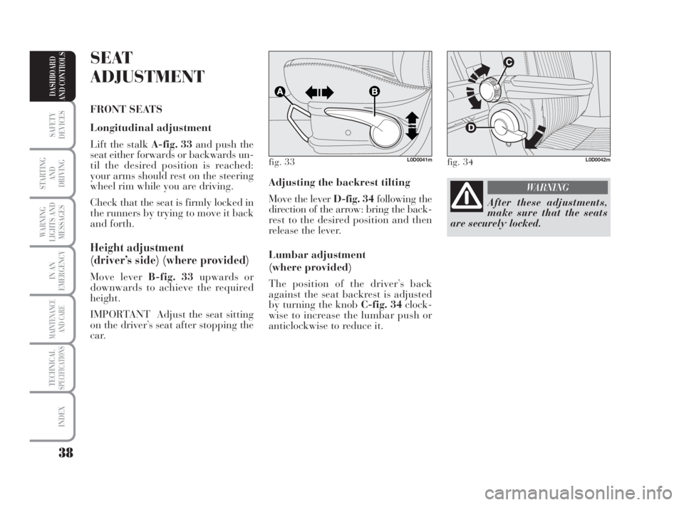
Adjusting the backrest tilting
Move the lever D-fig. 34following the
direction of the arrow: bring the back-
rest to the desired position and then
release the lever.
Lumbar adjustment
(where provided)
The position of the driver’s back
against the seat backrest is adjusted
by turning the knob C-fig. 34clock-
wise to increase the lumbar push or
anticlockwise to reduce it.
SEAT
ADJUSTMENT
FRONT SEATS
Longitudinal adjustment
Lift the stalk A-fig. 33and push the
seat either forwards or backwards un-
til the desired position is reached:
your arms should rest on the steering
wheel rim while you are driving.
Check that the seat is firmly locked in
the runners by trying to move it back
and forth.
Height adjustment
(driver’s side) (where provided)
Move lever B-fig. 33upwards or
downwards to achieve the required
height.
IMPORTANT Adjust the seat sitting
on the driver’s seat after stopping the
car.
fig. 33L0D0041mfig. 34L0D0042m
After these adjustments,
make sure that the seats
are securely locked.
WARNING
038-094 MUSA 3ed GB 12-11-2007 11:34 Pagina 38
Page 41 of 218
40
SAFETY
DEVICES
STARTING
AND
DRIVING
WARNING
LIGHTS AND
MESSAGES
IN AN
EMERGENCY
MAINTENANCE
AND CARE
TECHNICALSPECIFICATIONS
INDEX
DASHBOARD
AND CONTROLS
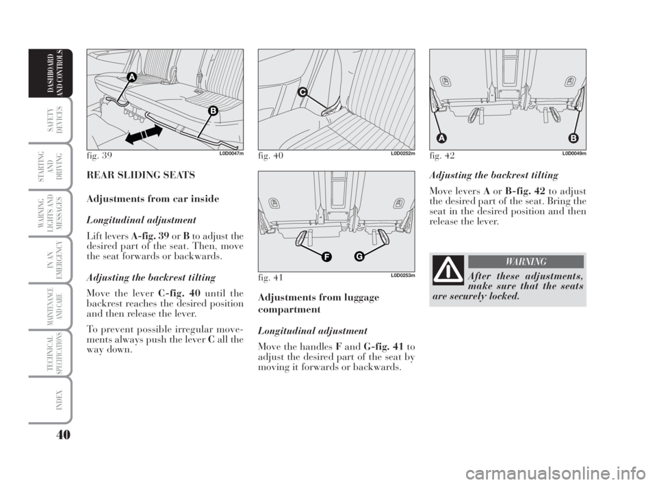
Adjusting the backrest tilting
Move levers AorB-fig. 42to adjust
the desired part of the seat. Bring the
seat in the desired position and then
release the lever.
Adjustments from luggage
compartment
Longitudinal adjustment
Move the handles FandG-fig. 41to
adjust the desired part of the seat by
moving it forwards or backwards. REAR SLIDING SEATS
Adjustments from car inside
Longitudinal adjustment
Lift levers A-fig. 39orBto adjust the
desired part of the seat. Then, move
the seat forwards or backwards.
Adjusting the backrest tilting
Move the lever C-fig. 40until the
backrest reaches the desired position
and then release the lever.
To prevent possible irregular move-
ments always push the lever Call the
way down.
fig. 39L0D0047mfig. 40L0D0252m
fig. 41L0D0253m
fig. 42L0D0049m
After these adjustments,
make sure that the seats
are securely locked.
WARNING
038-094 MUSA 3ed GB 12-11-2007 11:34 Pagina 40
Page 42 of 218
41
SAFETY
DEVICES
STARTING
AND
DRIVING
WARNING
LIGHTS AND
MESSAGES
IN AN
EMERGENCY
MAINTENANCE
AND CARE
TECHNICALSPECIFICATIONS
INDEX
DASHBOARD
AND CONTROLS
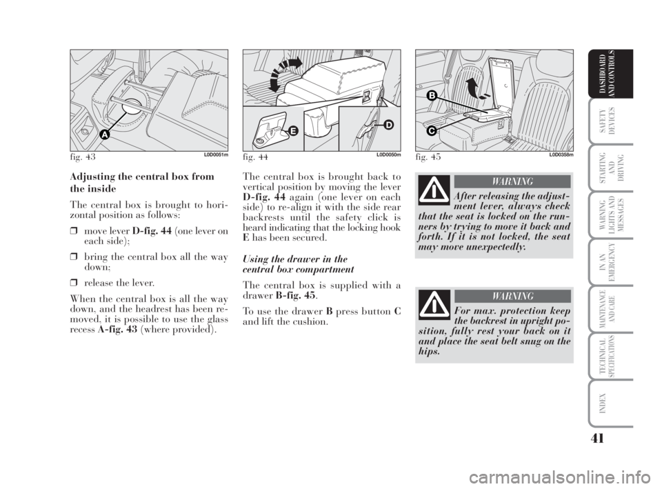
The central box is brought back to
vertical position by moving the lever
D-fig. 44again (one lever on each
side) to re-align it with the side rear
backrests until the safety click is
heard indicating that the locking hook
Ehas been secured.
Using the drawer in the
central box compartment
The central box is supplied with a
drawerB-fig. 45.
To use the drawer Bpress button C
and lift the cushion. Adjusting the central box from
the inside
The central box is brought to hori-
zontal position as follows:
❒move lever D-fig. 44(one lever on
each side);
❒bring the central box all the way
down;
❒release the lever.
When the central box is all the way
down, and the headrest has been re-
moved, it is possible to use the glass
recess A-fig. 43(where provided).
fig. 43L0D0051mfig. 44L0D0050mfig. 45L0D0358m
After releasing the adjust-
ment lever, always check
that the seat is locked on the run-
ners by trying to move it back and
forth. If it is not locked, the seat
may move unexpectedly.
WARNING
For max. protection keep
the backrest in upright po-
sition, fully rest your back on it
and place the seat belt snug on the
hips.
WARNING
038-094 MUSA 3ed GB 12-11-2007 11:35 Pagina 41
Page 43 of 218
42
SAFETY
DEVICES
STARTING
AND
DRIVING
WARNING
LIGHTS AND
MESSAGES
IN AN
EMERGENCY
MAINTENANCE
AND CARE
TECHNICALSPECIFICATIONS
INDEX
DASHBOARD
AND CONTROLS
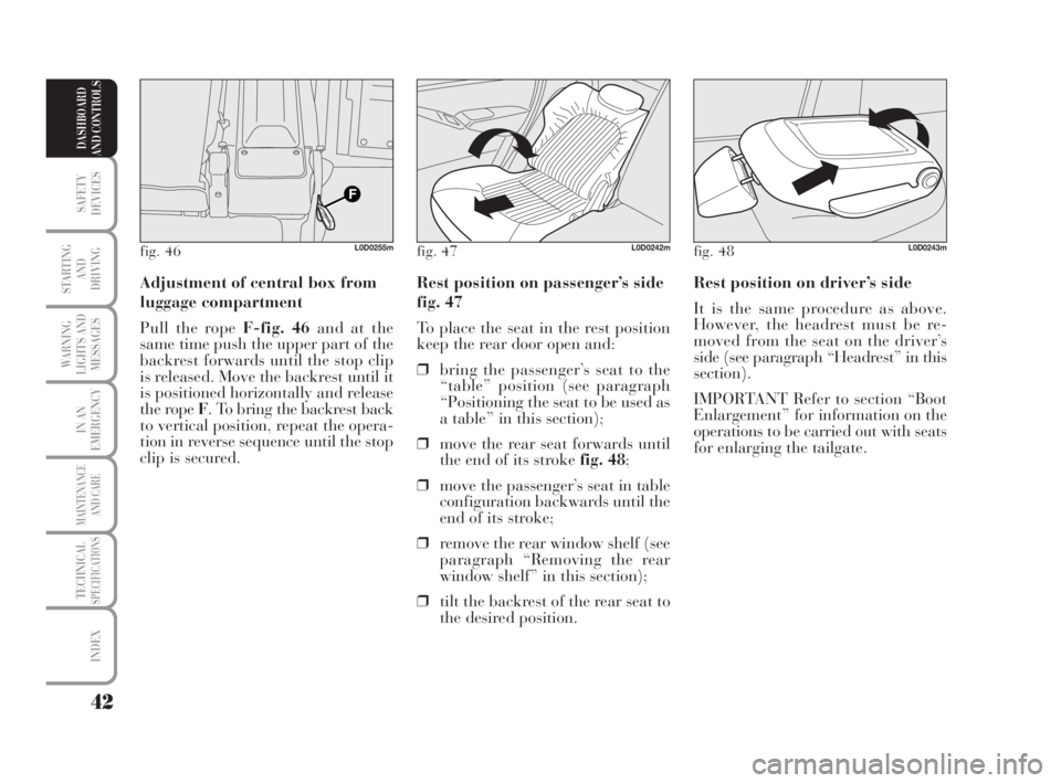
Rest position on driver’s side
It is the same procedure as above.
However, the headrest must be re-
moved from the seat on the driver’s
side (see paragraph “Headrest” in this
section).
IMPORTANT Refer to section “Boot
Enlargement” for information on the
operations to be carried out with seats
for enlarging the tailgate. Rest position on passenger’s side
fig. 47
To place the seat in the rest position
keep the rear door open and:
❒bring the passenger’s seat to the
“table” position (see paragraph
“Positioning the seat to be used as
a table” in this section);
❒move the rear seat forwards until
the end of its stroke fig. 48;
❒move the passenger’s seat in table
configuration backwards until the
end of its stroke;
❒remove the rear window shelf (see
paragraph “Removing the rear
window shelf” in this section);
❒tilt the backrest of the rear seat to
the desired position. Adjustment of central box from
luggage compartment
Pull the rope F-fig. 46and at the
same time push the upper part of the
backrest forwards until the stop clip
is released. Move the backrest until it
is positioned horizontally and release
the rope F. To bring the backrest back
to vertical position, repeat the opera-
tion in reverse sequence until the stop
clip is secured.
fig. 46L0D0255mfig. 47L0D0242mfig. 48L0D0243m
038-094 MUSA 3ed GB 12-11-2007 11:35 Pagina 42
Page 44 of 218
43
SAFETY
DEVICES
STARTING
AND
DRIVING
WARNING
LIGHTS AND
MESSAGES
IN AN
EMERGENCY
MAINTENANCE
AND CARE
TECHNICALSPECIFICATIONS
INDEX
DASHBOARD
AND CONTROLS
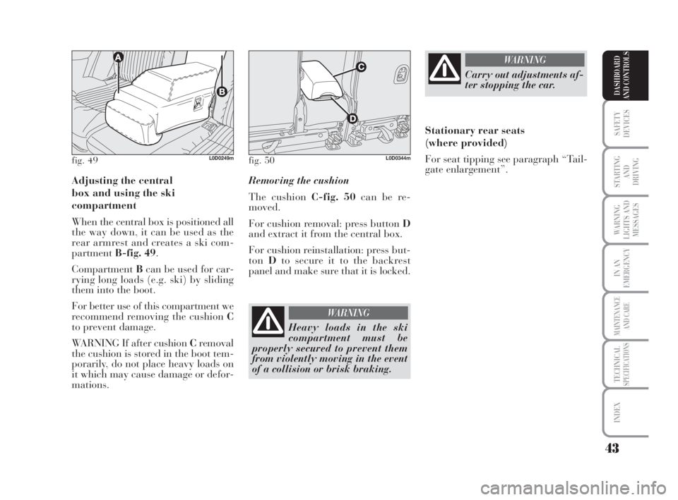
Adjusting the central
box and using the ski
compartment
When the central box is positioned all
the way down, it can be used as the
rear armrest and creates a ski com-
partmentB-fig. 49.
CompartmentBcan be used for car-
rying long loads (e.g. ski) by sliding
them into the boot.
For better use of this compartment we
recommend removing the cushion C
to prevent damage.
WARNING If after cushion Cremoval
the cushion is stored in the boot tem-
porarily, do not place heavy loads on
it which may cause damage or defor-
mations.Removing the cushion
The cushion C-fig. 50can be re-
moved.
For cushion removal: press button D
and extract it from the central box.
For cushion reinstallation: press but-
tonDto secure it to the backrest
panel and make sure that it is locked.
fig. 49L0D0249mfig. 50L0D0344m
Heavy loads in the ski
compartment must be
properly secured to prevent them
from violently moving in the event
of a collision or brisk braking.
WARNING
Carry out adjustments af-
ter stopping the car.
WARNING
Stationary rear seats
(where provided)
For seat tipping see paragraph “Tail-
gate enlargement”.
038-094 MUSA 3ed GB 12-11-2007 11:35 Pagina 43
Page 98 of 218
97
STARTING
AND
DRIVING
WARNING
LIGHTS AND
MESSAGES
IN AN
EMERGENCY
MAINTENANCE
AND CARE
TECHNICALSPECIFICATIONS
INDEX
DASHBOARD
AND CONTROLS
SAFETY
DEVICES
S.B.R. system
The car is fitted with a Seat Belt Re-
minder system (S.B.R.), consisting of
a buzzer and a flashing warning light
must be fastened.
The buzzer can be deactivated tem-
porarily (until the next engine stop)
as follows:
❒fasten the driver’s seat belt;
❒turn the ignition key to MAR
❒wait for over 20 seconds and then
release at least one of the seat
belts.
For permanent deactivation, contact
Lancia Dealership.
The S.B.R. system can be re-activated
through the “Setup” menu only (see
paragraph “Seat belts not fastened”
in section “Warning lights and mes-
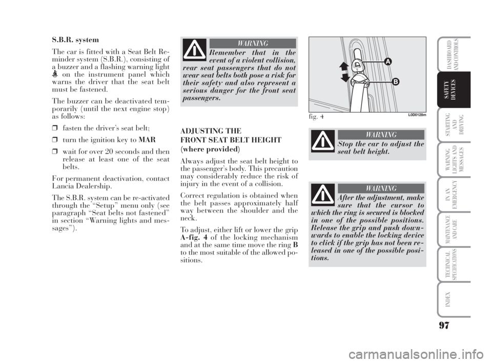
sages”).ADJUSTING THE
FRONT SEAT BELT HEIGHT
(where provided)
Always adjust the seat belt height to
the passenger’s body. This precaution
may considerably reduce the risk of
injury in the event of a collision.
Correct regulation is obtained when
the belt passes approximately half
way between the shoulder and the
neck.
To adjust, either lift or lower the grip
A-fig. 4of the locking mechanism
and at the same time move the ring B
to the most suitable of the allowed po-
sitions.
Remember that in the
event of a violent collision,
rear seat passengers that do not
wear seat belts both pose a risk for
their safety and also represent a
serious danger for the front seat
passengers.
WARNING
fig. 4L0D0128m
Stop the car to adjust the
seat belt height.
WARNING
After the adjustment, make
sure that the cursor to
which the ring is secured is blocked
in one of the possible positions.
Release the grip and push down-
wards to enable the locking device
to click if the grip has not been re-
leased in one of the possible posi-
tions.
WARNING
095-112 MUSA 3ed GB 12-11-2007 11:36 Pagina 97
Page 103 of 218
102
STARTING
AND
DRIVING
WARNING
LIGHTS AND
MESSAGES
IN AN
EMERGENCY
MAINTENANCE
AND CARE
TECHNICALSPECIFICATIONS
INDEX
DASHBOARD
AND CONTROLS
SAFETY
DEVICES
The research results in relation to the
best protection for children is illus-
trated in European standard ECE-
R44 which divides the restraint sys-
tems into five groups in addition to
making their use compulsory:
Group 0 - up to 10 kg in weight
Group 0+ - up to 13 kg in weight
Group 1 9-18 kg in weight
Group 2 15-25 kg in weight
Group 3 22-36 kg in weight
As it may be noted, the groups over-
lap partly and, in fact, in commerce it
is possible to find devices that cover
more than one weight group.
All restraint devices must bear the
type-approval data along with the
control mark on a label that must be
firmly secured to the child seat and
must never be removed.
Over 1.50 m in height, from the point
of view of restraint systems, children
are considered as adults and must
wear the seat belts normally.
Lineaccessori Lancia includes child
seats for each weight group. These de-
vices are recommended having been
specifically designed for Lancia cars.
SEVERE DANGER: do not
arrange child seats on the
front seat facing backwards if the
passenger’s front airbag is enabled.
Deployment of the airbag in the
event of an accident could cause fa-
tal injuries to the baby. It is advis-
able to carry children on the back
seat, which is the most protected
position in the event of an accident.
Under no circumstances should
child seats be fitted on the front
seat if the car is equipped with an
airbag on the passenger side, be-
cause if the airbag is deployed, it
may cause fatal injuries to the
baby regardless of the severity of
the crash causing the deployment.
WARNING
On cars supplied with a
deactivation system for
the front passenger
airbag, children can sit on
the front seat, when re-
quired. In this case, how-
ever, make sure that the airbag is
actually deactivated by checking
the amber warning light on the
panel (see the paragraph “front
airbag on passenger side” in the
section on both front and side
airbags). Move the passenger’s
seat as far back as possible to
avoid contact between the child
seat and the dashboard.
WARNING
095-112 MUSA 3ed GB 12-11-2007 11:36 Pagina 102
Page 104 of 218
103
STARTING
AND
DRIVING
WARNING
LIGHTS AND
MESSAGES
IN AN
EMERGENCY
MAINTENANCE
AND CARE
TECHNICALSPECIFICATIONS
INDEX
DASHBOARD
AND CONTROLS
SAFETY
DEVICES
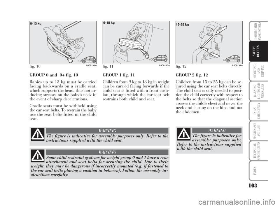
GROUP 0 and 0+ fig. 10
Babies up to 13 kg must be carried
facing backwards on a cradle seat,
which supports the head, thus not in-
ducing stresses on the baby’s neck in
the event of sharp decelerations.
Cradle seats must be withheld using
the car seat belts. To restrain the baby
use the seat belts fitted in the child
seat.GROUP 1 fig. 11
Children from 9 kg to 18 kg in weight
can be carried facing forwards if the
child seat is fitted with a front cush-
ion, through which the car seat belt
restrains both child and seat.
fig. 11L0D0137mfig. 12L0D0138mfig. 10L0D0136m
The figure is indicative for assembly purposes only. Refer to the
instructions supplied with the child seat.
WARNING
Some child restraint systems for weight group 0 and 1 have a rear
attachment and seat belts for securing the child. Due to their
weight, they may be dangerous if incorrectly mounted (e.g. if fastened to
the car seat belts placing a cushion in between). Follow the assembly in-
structions carefully.
WARNING
GROUP 2 fig. 12
Children from 15 to 25 kg can be se-
cured using the car seat belts directly.
The child seat is only needed to posi-
tion the child correctly with respect to
the belts so that the diagonal section
crosses the child’s chest and never the
neck and is snug on the hips and not
the abdomen.
The figure is indicative for
assembly purposes only.
Refer to the instructions supplied
with the child seat.
WARNING
095-112 MUSA 3ed GB 12-11-2007 11:36 Pagina 103