brake light Lancia Musa 2009 Owner handbook (in English)
[x] Cancel search | Manufacturer: LANCIA, Model Year: 2009, Model line: Musa, Model: Lancia Musa 2009Pages: 218, PDF Size: 3.7 MB
Page 115 of 218
114
WARNING
LIGHTS AND
MESSAGES
IN AN
EMERGENCY
MAINTENANCE
AND CARE
TECHNICALSPECIFICATIONS
INDEX
DASHBOARD
AND CONTROLS
SAFETY
DEVICES
STARTING
AND
DRIVING
STARTING
THE ENGINE
The car is provided with an electronic
engine lock device: refer to “The Lan-
cia CODE system” paragraph in
“Dashboard and controls” if you can-
not start the engine. The engine may
be noisier during the first seconds of
operation, particularly after a long pe-
riod of inactivity. This does not impair
functionality and reliability and is
typical of hydraulic tappets: the dis-
tribution system selected for the petrol
engines of your car in order to limit
the maintenance required.
STARTING PROCEDURE FOR
PETROL VERSIONS
Proceed as follows:
❒ensure that the handbrake is up;
❒put the gear lever into neutral;
❒press the clutch pedal down to the
floor without touching the accel-
erator;
❒turn the ignition to AV Vand re-
lease the key as soon as the engine
starts.If the engine does not start at the first
attempt, return the ignition key to
STOPbefore repeating starting.
If, when the ignition key is on MAR,
the instrument panel warning light
Yremains on together with the
warning light U, turn the key to
STOPand then back to MAR; if the
warning light remains on, try with the
other keys provided with the car.
Is is dangerous to let the en-
gine run in enclosed spaces.
The engine depletes the oxygen and
discharges carbon dioxide, carbon
monoxide and other toxic gases.
WARNING
In the first period of use, we
recommend to avoid exces-
sive stress for the car (for in-
stance excessive accelera-
tions, extended travel at maximum
speed, sudden braking etc.).
With engine off, do not leave
the key in the ignition switch
on MAR to prevent draining
the battery.
If you still cannot start the engine,
perform emergency start (see “Emer-
gency start” in chapter “In an emer-
gency”) and then contact a Lancia
Dealership.
IMPORTANT Never leave the ignition
key to MARwhen the engine is off.
STARTING PROCEDURE FOR
MULTIJET VERSIONS
Proceed as follows:
❒ensure that the handbrake is up;
❒put the gear lever into neutral;
❒turn the ignition key to MAR; the
instrument panel warning lights
m,
UandY;
113-124 MUSA 1ed GB 10-07-2008 9:37 Pagina 114
Page 117 of 218
116
WARNING
LIGHTS AND
MESSAGES
IN AN
EMERGENCY
MAINTENANCE
AND CARE
TECHNICALSPECIFICATIONS
INDEX
DASHBOARD
AND CONTROLS
SAFETY
DEVICES
STARTING
AND
DRIVING
PARKING THE CAR
Proceed as follows:
❒stop the engine and engage the
handbrake;
❒when on a slope, engage a gear
(engage first gear if the car is
faced uphill or reverse if it is faced
downhill) and leave the wheels
steered.
When parking the car on a steep
slope, it is advisable to also place a
wedge or a rock under the wheels.
PROLONGED parking with a wheel
on the pavement or steered against a
step should be avoided. Do not leave
the ignition key on MARto prevent
draining the battery. Always remove
the key when you leave the car.
HANDBRAKE
The handbrake lever is located be-
tween the two front seats.
Pull the lever upwards to operate the
handbrake.
Four or five notches are normally suf-
ficient to lock the car on flat terrain,
while nine or ten may be necessary on
a steep slope with the car loaded. IMPORTANT If this is not the case,
contact a Lancia Dealership to have
the handbrake adjusted.
When the handbrake lever is pulled
up and the ignition key is on MAR,
the instrument panel warning light
xwill turn on.
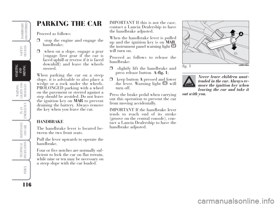
Proceed as follows to release the
handbrake:
❒slightly lift the handbrake and
press release button A-fig. 1;
❒keep button Apressed and lower
the lever. Warning light
xwill
turn off.
Press the brake pedal when carrying
out this operation to prevent the car
from moving accidentally.
IMPORTANT If the handbrake lever
tends to reach end of its stroke
(groove on the central console), con-
tact a Lancia Dealership to have the
handbrake adjusted.
fig. 1L0D0149m
Never leave children unat-
tended in the car. Always re-
move the ignition key when
leaving the car and take it
out with you.
113-124 MUSA 1ed GB 10-07-2008 9:37 Pagina 116
Page 120 of 218
119
WARNING
LIGHTS AND
MESSAGES
IN AN
EMERGENCY
MAINTENANCE
AND CARE
TECHNICALSPECIFICATIONS
INDEX
DASHBOARD
AND CONTROLS
SAFETY
DEVICES
STARTING
AND
DRIVING
Top speed
Fuel consumption considerably in-
creases as speed increases. Keep your
speed as even as possible, avoiding
unnecessary braking and acceleration
which cause excessive fuel consump-
tion and increase emissions.
Acceleration
Sudden acceleration has a very nega-
tive effect on consumptions and emis-
sions: accelerate gradually and do not
go over the maximum torque ratio.CONDITIONS OF USE
Cold starting
Short distances and frequent cold
start-ups will prevent the engine from
reaching optimal running tempera-
ture. Consequently, both consumption
(from +15 to +30% on urban cycle )
and emissions will increase.
Traffic and road conditions
Rather high consumption is caused by
heavy traffic, for instance when trav-
elling in a queue with frequent use of
low gears or in cities with many traf-
fic lights. Mountain and rough roads
also have a negative effect on con-
sumption.
Traffic hold-ups
During prolonged hold-ups (level
crossings) the engine should be
switched off.TOWING TRAILERS
IMPORTANT NOTES
The car must be provided with a
type-approved tow hitch and ade-
quate electrical system to tow cara-
vans or trailers. Installation must be
performed by specialised personnel
who will issue the required papers for
travelling on roads.
Install any specific and/or additional
rear-view mirrors as specified by law.
Remember that when towing a trailer,
steep hills are harder to climb, the
braking spaces increase and overtak-
ing takes longer depending on the
overall weight.
When driving downhill engage a low
gear, rather than constantly using the
brake.
113-124 MUSA 1ed GB 10-07-2008 9:37 Pagina 119
Page 121 of 218
120
WARNING
LIGHTS AND
MESSAGES
IN AN
EMERGENCY
MAINTENANCE
AND CARE
TECHNICALSPECIFICATIONS
INDEX
DASHBOARD
AND CONTROLS
SAFETY
DEVICES
STARTING
AND
DRIVING
The weight of the trailer on the car tow
hook reduces of the same value the load
capacity of the car. Consider the weight
of the car at full load, including acces-
sories and luggage to make sure you do
not exceed the maximum towable
weight (shown on the log book).
Respect the speed limits specific for
each country for vehicles towing trail-
ers. In all cases, the top speed must
not exceed 100 km/h.
The ABS with which the car
is equipped will not control
the braking system of the trailer.
Take specific care when travelling on
slippery roads.
WARNING
Never modify the braking
system of the car to control
the trailer brake. The trailer brak-
ing system must be fully indepen-
dent from the hydraulic system of
the car.
WARNING
INSTALLING THE
TOW HOOK
The towing device should be fastened
to the body by specialised personnel
according to any additional and/or in-
tegrative information supplied by the
Manufacturer of the device.
The towing device must meet current
regulations with reference to
94/20/EC Directive and subsequent
amendments.
For any version the towing device
used must match the towable weight
of the car on which it is to be in-
stalled.
For the electric connection a unified
connector should be used which is
generally placed on a special bracket
normally fastened to the towing de-
vice, and a special ECU for external
trailer light control shall be installed
on the car. For the electrical connection, 7 or 13
pin 12VDC connection is to be used
(CUNA/UNI and ISO/DIN Stan-
dards). Follow the instructions pro-
vided by the car manufacturer and/or
the tow hitch manufacturer.
An electric brake should be supplied
directly by the battery through a ca-
ble with a cross section of no less than
2.5 mm
2.
IMPORTANT Electric brake or other
device shall be used with running en-
gine.
In addition to the electrical branches,
the car’s electric system can only be
connected to the supply cable for an
electric brake and to the cable for an
internal light, though not above 15W.
For connections use the preset control
unit with battery cable no less than
2.5 mm
2.
113-124 MUSA 1ed GB 10-07-2008 9:37 Pagina 120
Page 125 of 218
124
WARNING
LIGHTS AND
MESSAGES
IN AN
EMERGENCY
MAINTENANCE
AND CARE
TECHNICALSPECIFICATIONS
INDEX
DASHBOARD
AND CONTROLS
SAFETY
DEVICES
STARTING
AND
DRIVING
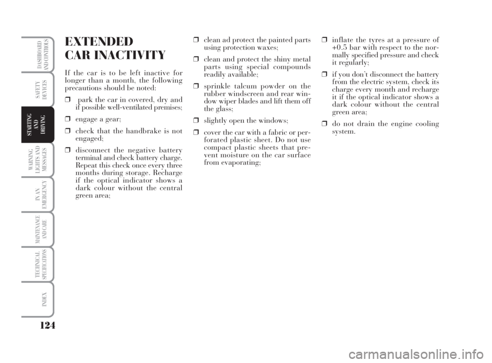
EXTENDED
CAR INACTIVITY
If the car is to be left inactive for
longer than a month, the following
precautions should be noted:
❒park the car in covered, dry and
if possible well-ventilated premises;
❒engage a gear;
❒check that the handbrake is not
engaged;
❒disconnect the negative battery
terminal and check battery charge.
Repeat this check once every three
months during storage. Recharge
if the optical indicator shows a
dark colour without the central
green area;❒clean ad protect the painted parts
using protection waxes;
❒clean and protect the shiny metal
parts using special compounds
readily available;
❒sprinkle talcum powder on the
rubber windscreen and rear win-
dow wiper blades and lift them off
the glass;
❒slightly open the windows;
❒cover the car with a fabric or per-
forated plastic sheet. Do not use
compact plastic sheets that pre-
vent moisture on the car surface
from evaporating;❒inflate the tyres at a pressure of
+0.5 bar with respect to the nor-
mally specified pressure and check
it regularly;
❒if you don’t disconnect the battery
from the electric system, check its
charge every month and recharge
it if the optical indicator shows a
dark colour without the central
green area;
❒do not drain the engine cooling
system.
113-124 MUSA 1ed GB 10-07-2008 9:37 Pagina 124
Page 126 of 218
125
IN AN
EMERGENCY
MAINTENANCE
AND CARE
TECHNICALSPECIFICATIONS
INDEX
DASHBOARD
AND CONTROLS
SAFETY
DEVICES
STARTING
AND
DRIVING
USE OF
THE CAR
WARNING
LIGHTS AND
MESSAGES
WARNING LIGHTS AND MESSAGES
GENERAL WARNINGS..................................... 126
LOW BRAKE FLUID......................................... 126
HANDBRAKE ON.............................................. 126
AIRBAG FAILURE............................................ 126
HOT ENGINE COOLANT................................. 127
LOW BATTERY CHARGE................................ 127
LOW ENGINE OIL PRESSURE .......................... 128
EXHAUSTED OIL ............................................ 128
“DUALDRIVE” ELECTRIC
POWER STEERING FAILURE ........................ 128
INCOMPLETE DOOR LOCKING...................... 128
SEAT BELTS NOT FASTENED ........................... 128
EBD SYSTEM FAILURE................................... 129
INJECTION SYSTEM FAILURE........................ 129
EOBD ENGINE CONTROL
SYSTEM FAILURE .......................................... 129
FRONT PASSENGER AIRBAG DEACTIVATED 130
ABS SYSTEM FAILURE.................................... 130
FUEL RESERVE............................................... 130
GLOW PLUG HEATING.................................. 131
GLOW PLUG HEATING FAILURE................... 131
WATER IN DIESEL FUEL FILTER.................. 131LANCIA CODE PROTECTION
SYSTEM FAILURE........................................... 131
REAR FOG LIGHTS.......................................... 131
GENERIC FAILURE INDICATION ................... 132
BRAKE PAD WEAR ......................................... 133
PARTICULATE TRAP CLOGGED ................... 133
TAIL LIGHTS AND LOW BEAMS..................... 133
FOLLOW ME HOME........................................ 133
FRONT FOG LIGHTS ...................................... 133
LEFT-HAND DIRECTION INDICATOR............ 134
RIGHT-HAND DIRECTION INDICATOR.......... 134
“DUALDRIVE” ELECTRIC
POWER STEERING ......................................... 134
CRUISE CONTROL .......................................... 134
MAIN BEAM HEADLIGHTS.............................. 134
POSSIBLE ICE ON THE ROAD ........................ 134
LIMITED RANGE ............................................. 134
125-134 MUSA 1ed GB 10-07-2008 9:38 Pagina 125
Page 127 of 218
126
IN AN
EMERGENCY
MAINTENANCE
AND CARE
TECHNICALSPECIFICATIONS
INDEX
DASHBOARD
AND CONTROLS
SAFETY
DEVICES
STARTING
AND
DRIVING
WARNING
LIGHTS AND
MESSAGES
GENERAL WARNINGS
Lighting of a warning light is associated
to a specific message and/or buzzer
when applicable. These indications are
brief and precautionary and as such
must not be considered as exhaustive
and/or alternative to the information
contained in the Owner’s Handbook,
which you are recommended to read
carefully in all cases. Always refer to the
information in this chapter in the event
of a failure indication.
IMPORTANT Failure indications on
the display fall into either of two cat-
egories:seriousfailure and less seri -
ousfailure.
Seriousfailures indicate a “cycle” of
warning messages that stay on until
the cause of the failure is eliminated.
Less seriousfailures are indicated by
a limited warning “cycle”.
PressMODEto stop the warning cy-
cle in both cases. The warning light
on the instrument panel will stay on
until the cause of the failure is elimi-
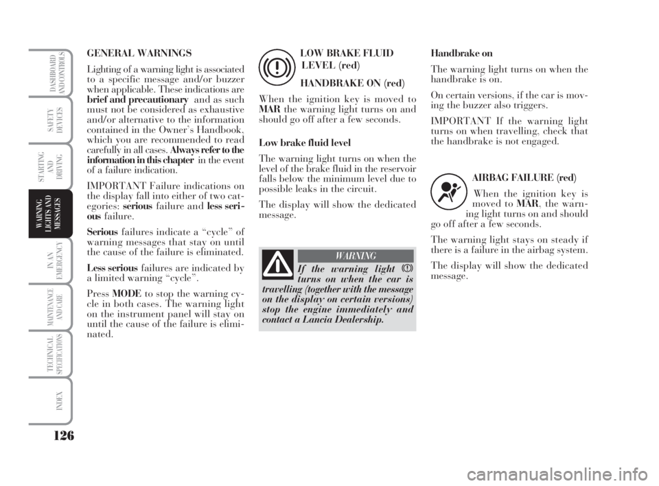
nated.LOW BRAKE FLUID
LEVEL (red)
HANDBRAKE ON (red)
When the ignition key is moved to
MARthe warning light turns on and
should go off after a few seconds.
Low brake fluid level
The warning light turns on when the
level of the brake fluid in the reservoir
falls below the minimum level due to
possible leaks in the circuit.
The display will show the dedicated
message.
x
Handbrake on
The warning light turns on when the
handbrake is on.
On certain versions, if the car is mov-
ing the buzzer also triggers.
IMPORTANT If the warning light
turns on when travelling, check that
the handbrake is not engaged.
AIRBAG FAILURE (red)
When the ignition key is
moved to MAR, the warn-
ing light turns on and should
go off after a few seconds.
The warning light stays on steady if
there is a failure in the airbag system.
The display will show the dedicated
message.
¬
If the warning light x
turns on when the car is
travelling (together with the message
on the display on certain versions)
stop the engine immediately and
contact a Lancia Dealership.
WARNING
125-134 MUSA 1ed GB 10-07-2008 9:38 Pagina 126
Page 134 of 218
133
IN AN
EMERGENCY
MAINTENANCE
AND CARE
TECHNICALSPECIFICATIONS
INDEX
DASHBOARD
AND CONTROLS
SAFETY
DEVICES
STARTING
AND
DRIVING
USE OF
THE CAR
WARNING
LIGHTS AND
MESSAGES
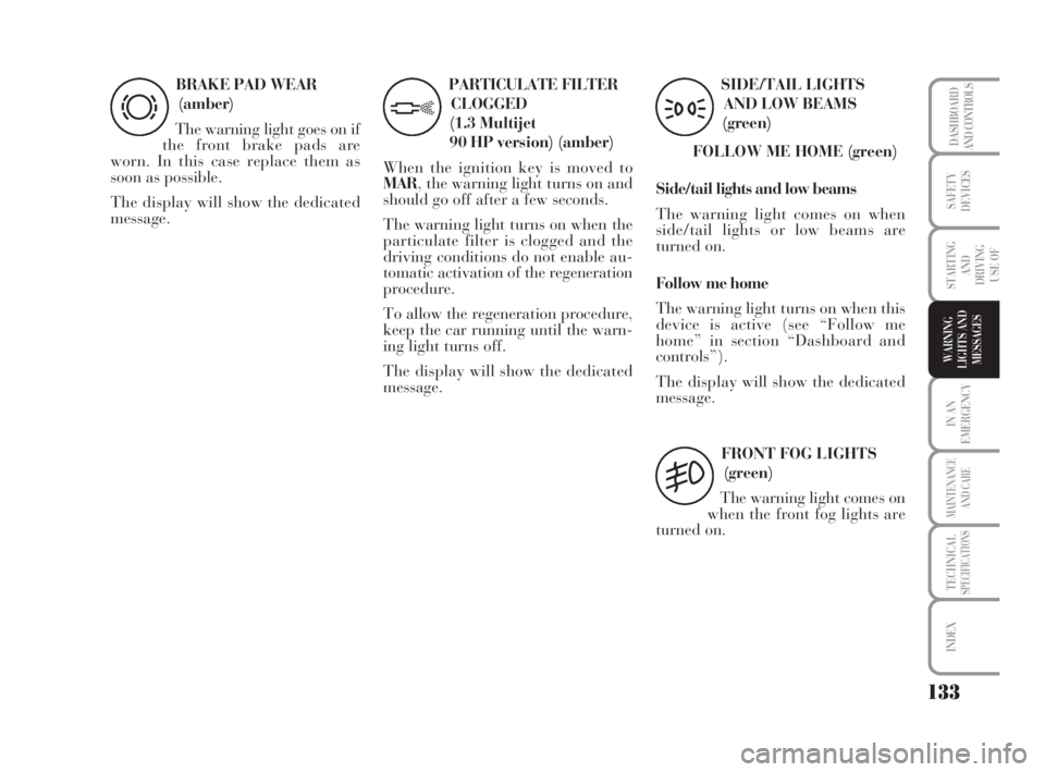
BRAKE PAD WEAR
(amber)
The warning light goes on if
the front brake pads are
worn. In this case replace them as
soon as possible.
The display will show the dedicated
message.
d
PARTICULATE FILTER
CLOGGED
(1.3 Multijet
90 HP version) (amber)
When the ignition key is moved to
MAR, the warning light turns on and
should go off after a few seconds.
The warning light turns on when the
particulate filter is clogged and the
driving conditions do not enable au-
tomatic activation of the regeneration
procedure.
To allow the regeneration procedure,
keep the car running until the warn-
ing light turns off.
The display will show the dedicated
message.
h
SIDE/TAIL LIGHTS
AND LOW BEAMS
(green)
FOLLOW ME HOME (green)
Side/tail lights and low beams
The warning light comes on when
side/tail lights or low beams are
turned on.
Follow me home
The warning light turns on when this
device is active (see “Follow me
home” in section “Dashboard and
controls”).
The display will show the dedicated
message.
3
FRONT FOG LIGHTS
(green)
The warning light comes on
when the front fog lights are
turned on.
5
125-134 MUSA 1ed GB 10-07-2008 9:38 Pagina 133
Page 139 of 218
138
WARNING
LIGHTS AND
MESSAGES
MAINTENANCE
AND CARE
TECHNICALSPECIFICATIONS
INDEX
DASHBOARD
AND CONTROLS
SAFETY
DEVICES
STARTING
AND
DRIVING
IN AN
EMERGENCY
Indicate that the car is sta-
tionary according to the laws
in force: emergency lights, refracting
warning triangle, etc. Passengers
should leave the car, particularly if it
is very loaded and wait for the wheel
to be changed away from on-coming
traffic. In case of steep slopes or
rough slopes, place wedges or other
materials suitable to stop the vehicle
under the wheels.
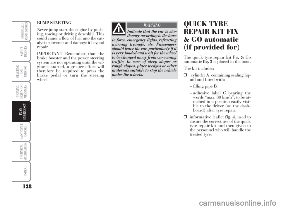
WARNINGQUICK TYRE
REPAIR KIT FIX
& GO automatic
(if provided for)
The quick tyre repair kit Fix & Go
automaticfig. 3is placed in the boot.
The kit includes:
❒cylinderAcontaining sealing liq-
uid and fitted with:
– filling pipe B;
– adhesive label Cbearing the
words “max. 80 km/h”, to be at-
tached in a position easily visi-
ble to the driver (on the dash-
board) after tyre repair;
❒informative leaflet fig. 4, used to
ensure the correct use of the quick
tyre repair kit and then given to
the personnel who will handle the
treated tyre; BUMP STARTING
Never jump start the engine by push-
ing, towing or driving downhill. This
could cause a flow of fuel into the cat-
alytic converter and damage it beyond
repair.
IMPORTANT Remember that the
brake booster and the power steering
system are not operating until the en-
gine is started, a greater effort will
therefore be required to press the
brake pedal or turn the steering
wheel.
135-164 MUSA 1ed GB 10-07-2008 9:38 Pagina 138
Page 141 of 218
140
WARNING
LIGHTS AND
MESSAGES
MAINTENANCE
AND CARE
TECHNICALSPECIFICATIONS
INDEX
DASHBOARD
AND CONTROLS
SAFETY
DEVICES
STARTING
AND
DRIVING
IN AN
EMERGENCY
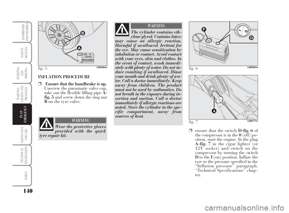
INFLATION PROCEDURE
❒Ensure that the handbrake is up.
Unscrew the pneumatic valve cap,
take out the flexible filling pipe A-
fig. 5and screw down the ring nut
Bon the tyre valve;
fig. 5L0D0484m
Wear the protective gloves
provided with the quick
tyre repair kit.
WARNING
The cylinder contains eth-
ylene glycol. Contains latex:
may cause an allergic reaction.
Harmful if swallowed. Irritant for
the eye. May cause sensitization by
inhalation or contact. Avoid contact
with your eyes, skin and clothes. In
the event of contact, wash immedi-
ately with plenty of water. Do not in-
duce vomiting if swallowed. Rinse
your mouth and drink plenty of wa-
ter. Call a doctor immediately. Keep
away from children. The product
must not be used by asthmatics. Do
not breath in the vapours during in-
sertion and suction. Call a doctor
immediately if allergic reactions are
noted. Store the cylinder in the spe-
cific compartment, away from
sources of heat.
WARNING
❒ensure that the switch D-fig. 6of
the compressor is in the 0(off) po-
sition, start the engine, fit the plug
A-fig. 7in the cigar lighter (or
12V socket) and switch on the
compressor by turning the switch
Dto the I(on) position. Inflate the
tyre to the pressure specified in the
“Inflation pressure” paragraph,
“Technical Specifications” chap-
ter.
fig. 6L0D0364m
fig. 7L0D0177m
135-164 MUSA 1ed GB 10-07-2008 9:38 Pagina 140